
|
|
Forum Index : Microcontroller and PC projects : CMM2 demo programs
| Page 1 of 4 |
|||||
| Author | Message | ||||
TassyJim Guru Joined: 07/08/2011 Location: AustraliaPosts: 5899 |
During the testing of the CMM2, I needed a few short programs designed to demonstrate some of the features. This rotating cube program started life in a QuickBasic forum. To change it to MMBasic the only changes needed were PSET changed to PIXEL and BOX used to erase the frames. I then used PAGE to remove the ficker and a timer so you can compare the different graphic MODEs A couple of tweaks to the formula shaved about 10mS of each frame.  ' cube rotator ' From a 19 liner by Entropy, shrinked by Antoni Gual ' for Rel's 9 LINER contest at QBASICNEWS.COM 1/2003 ' translated to MMBasic for the CMM2 by TassyJim May 2020 DIM INTEGER x,y,z DIM FLOAT r,x1,y1 DIM FLOAT COSr,SINr,denom,xyz DIM INTEGER cx = MM.HRES/2 'scale things for different display resolution DIM INTEGER cy = MM.VRES/2 DIM INTEGER b = cx/2 DIM INTEGER s = cx*3/4 CLS DO TIMER = 0 PAGE WRITE 1 'cls BOX b,cy-b,cx,cx,1,0,0 ' 1mS quicker than CLS r = (r + .01745) + 6.283185 * (r >= 6.283185) COSr = COS(r) SINr = SIN(r) FOR x = -30 TO 30 STEP 10 FOR y = -30 TO 30 STEP 10 FOR z = -30 TO 30 STEP 10 denom = x*SINr+(z*COSr-y*SINr)*COSr+100 ' saves about 4.5mS xyz = x*COSr-(z*COSr-y*SINr)*SINr ' this one saves 3mS x1 =(xyz*COSr+(y*COSr+z*SINr)*SINr)/denom y1 =((y*COSr+z*SINr)*COSr-xyz*SINr)/denom PIXEL (s * x1 + cx), (s * y1 + cy), RGB(WHITE) NEXT z NEXT y NEXT x PAGE WRITE 0 BLIT b,cy-b, b,cy-b,cx,cx ,1 TEXT cx,cy+b,STR$(TIMER)+"mS",cm LOOP UNTIL INKEY$ <>"" ' formula before speed refinements ' x1 =((x*COS(r)-(z*COS(r)-y*SIN(r))*SIN(r))*COS(r)+(y*COS(r)+z*SIN(r))*SIN(r))/(x*SIN(r)+(z*COS(r)-y*SIN(r))*COS(r)+100) ' y1 =((y*COS(r)+z*SIN(r))*COS(r)-(x*COS(r)-(z*COS(r)-y*SIN(r))*SIN(r))*SIN(r))/(x*SIN(r)+(z*COS(r)-y*SIN(r))*COS(r)+100) Jim VK7JH MMedit MMBasic Help |
||||
| TassyJim Guru Joined: 07/08/2011 Location: AustraliaPosts: 5899 |
Sudoku This program incorporates a method of solving the puzzle which I found in the QB64 samples. The code was very condensed which makes understanding the process difficult (for me). It also has lots of GOTOs which I have only partially removed. It does succeed most of the time. MMBasic has limits on the amount of recursion you can do so the more usually solving algorithms were not available. I could have cheated by saving a copy of the solved puzzle before starting but that�s not fair. At any time, the �H� key toggles hints on/off �Enter� lets the CCM2 solve it for you. 600 lines so I ZIPed it. sudoku.zip Jim VK7JH MMedit MMBasic Help |
||||
| TassyJim Guru Joined: 07/08/2011 Location: AustraliaPosts: 5899 |
I started writing my File Manager before the inbuilt FILES command was expanded and decided to keep going. It has been useful to understand and test how MMBasic on the CMM2 handles the various file types. I have put in a few tests to catch some of the files that MMBasic doesn't handle such as oversize images but there are still plenty of ways to cause it to crash. 'h' for help FM.zip Jim VK7JH MMedit MMBasic Help |
||||
Grogster Admin Group Joined: 31/12/2012 Location: New ZealandPosts: 9060 |
Cube demo is EXCELLENT, Jim!  Smoke makes things work. When the smoke gets out, it stops! |
||||
| TassyJim Guru Joined: 07/08/2011 Location: AustraliaPosts: 5899 |
ColourBars is a short program to test all available graphics modes. It can be tricky to set up a monitor to display all modes without trimming off pixels from one edge in some modes. This program helps. It also lets you find the optimum aspect ratio needed for the CIRCLE command. This will vary between monitors. colourBars.zip Jim VK7JH MMedit MMBasic Help |
||||
| TassyJim Guru Joined: 07/08/2011 Location: AustraliaPosts: 5899 |
This is one that serves no purpose at all. To change it from QB64, I added the colours array and changed PSET to PIXEL and set the MODE 'sinecube QB64 2006 mennonite 'translated to MMBasic by TassyJim May2020 DIM blox(40, 40, 40) AS INTEGER DIM col(15) ' GWBasic colours col(0) = RGB(BLACK) col(1) = RGB(BLUE) col(2) = RGB(GREEN) col(3) = RGB(CYAN) col(4) = RGB(RED) col(5) = RGB(MAGENTA) col(6) = RGB(150, 75, 0) ' brown col(7) = RGB(192,192,192) ' dull white col(8) = RGB(127,127,127) ' grey col(9) = RGB(173, 216, 230) ' light blue col(10) = RGB(173, 216, 230)' light green col(11) = RGB(144, 238, 144)' light cyan col(12) = RGB(255, 100, 100)' light red col(13) = RGB(255, 120, 255)' light magenta col(14) = RGB(YELLOW) ' yellow col(15) = RGB(WHITE) ' bright white MODE 2,16 CLS B$ = "00000000...llnnnnnnl..l8lnnnnnnl.l88lllllllll88l000000ll88l00000" B$ = B$ + "0ll88l000000ll88l000000l.l8l000000l..ll000000l...llllllll" l = 8 blox(2, 3, 32) = 1 FOR l = 8 * 32 TO 1 STEP -8 FOR y = 4 TO 4 * 32 STEP 4 FOR x = 8 * 32 TO 1 STEP -8 mm = SIN(x * y * l * 3.14): IF mm<0 THEN mm=-1 ELSE IF mm>0 THEN mm=1 IF blox(x / 8, y / 4, l / 8) = mm + 1 THEN FOR by = 1 TO 11 FOR bx = 1 TO 11 IF RIGHT$(LEFT$(b$,(by - 1) * 11 + bx),1) <> "." THEN z = 11 c = ASC(RIGHT$(LEFT$(b$,(by - 1) * 11 + bx),1)) MOD 16 + (y MOD 2) PIXEL x + bx - 1 + y - 3, by - 1 + y + l + 4, col(c) END IF NEXT bx NEXT by END IF IF INKEY$ = CHR$(27) THEN END NEXT x NEXT y NEXT l mode 1,8 Jim VK7JH MMedit MMBasic Help |
||||
| TassyJim Guru Joined: 07/08/2011 Location: AustraliaPosts: 5899 |
I really need to get out more: 'Lissajous by Antoni Gual ' for Rel's 9 LINER contest at QBASICNEWS.COM 1/2003 ' converted to MMBasic for the CMM2 by TassyJim May 2020 DIM col(15) ' GWBasic colours col(0) = RGB(BLACK) col(1) = RGB(BLUE) col(2) = RGB(GREEN) col(3) = RGB(CYAN) col(4) = RGB(RED) col(5) = RGB(MAGENTA) col(6) = RGB(150, 75, 0) ' brown col(7) = RGB(192,192,192) ' dull white col(8) = RGB(127,127,127) ' grey col(9) = RGB(173, 216, 230) ' light blue col(10) = RGB(173, 216, 230)' light green col(11) = RGB(144, 238, 144)' light cyan col(12) = RGB(255, 100, 100)' light red col(13) = RGB(255, 120, 255)' light magenta col(14) = RGB(YELLOW) ' yellow col(15) = RGB(WHITE) ' bright white DIM INTEGER i , n DIM FLOAT k,l,j MODE 2,8 DO CLS i = (i + 1) AND &HFFFFF k = 6.3 * RND() l = 6.3 * RND() n = (n + 1) MOD 15 FOR j = 0 TO 100000 PIXEL 320 + 300 * SIN(.01 * SIN(k) + j), 240 + 200 * SIN(.01 * SIN(l) * j), col(n + 1) NEXT j LOOP UNTIL INKEY$ <>"" MODE 1,8 Give it time to cycle through a few patterns. Jim VK7JH MMedit MMBasic Help |
||||
| matherp Guru Joined: 11/12/2012 Location: United KingdomPosts: 8578 |
Julia and mandlebrot map maximite 'Specify initial values RealOffset = -1.5 '-1.30 RIGHT-left ImaginOffset = -1.1 '1.0 '-1.22 Top-Bottom '------------------------------------------------* 'Set the Julia set constant [eg C = -1.2 + 0.8i] CRealVal = -0.78 CImagVal = -0.20 '------------------------------------------------* MAXIT=30'0 '80 'max iterations PixelWidth = MM.HRes PixelHeight = MM.VRes GAP = PixelHeight / PixelWidth SIZE = 2.9 '2.50 - bigger value = smaller width XDelta = SIZE / PixelWidth YDelta = (SIZE * GAP) / PixelHeight 'Loop processing - visit every pixel For X = 0 To (PixelWidth - 1) CX = X * Xdelta + RealOffset For Y = 0 To (PixelHeight - 1) CY = Y * YDelta + ImaginOffset Zr = CX Zi = CY COUNT = 0 'Begin Iteration loop Do While (( COUNT <= MAXIT ) And (( Zr * Zr + Zi * Zi ) < 4 )) new_Zr = Zr * Zr - Zi * Zi + CRealVal new_Zi = 2 * Zr * Zi + CImagVal Zr = new_Zr Zi = new_Zi COUNT = COUNT + 1 Loop Pixel X,Y,map(COUNT Mod 8 +48) Next Y Next X save image "Julia2.bmp" Do a$ = Inkey$ Loop While a$ = "" sizex%=800 sizey%=600 maxiter%=64 'Option console off CLS For X% = 0 To 2*sizex%-2 Step 2 xi = X%/200 - 2 For Y% = 0 To sizey%-2 Step 2 yi = Y% / 200 xx = 0 yy = 0 For I% = 1 To maxiter% If xx*xx+yy*yy > 4 Then Exit For xt = xi + xx*xx-yy*yy yy = yi + 2*xx*yy xx = xt Next If I%>=maxiter% Then I%=0 Box X%,Y%+300,2,2,,map(i%*4) : Box X%,-Y%+300,2,2,,map(i%*4) Next Y% Next X% |
||||
| matherp Guru Joined: 11/12/2012 Location: United KingdomPosts: 8578 |
Rotating Dodecahedron Check the video 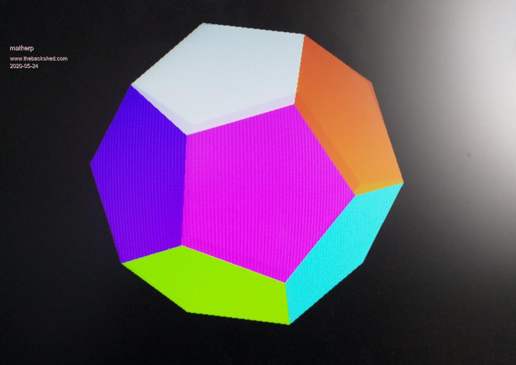 option explicit option default none page write 1 const edgelength=200 'set the length of the verticies of the dodecahedron const zlocation=1000 'how far is the center of the dodecahedron away from us const viewplane=800 'how far is the viewplane away from us dim float xarr(4),yarr(4) dim float phi=(1+sqr(5))/2 ' golden ratio dim float x,y,x1,y1,z1 dim integer col(11), sortorder(11) dim float q1(4),depth(11),v(4), vout(4) ' data for location of verticies for dodecahedron of edge length 2 data phi,phi,phi data phi,phi,-phi data phi,-phi,phi data -phi,phi,phi data -phi,-phi,phi data -phi,phi,-phi data phi,-phi,-phi data -phi,-phi,-phi data 0,-(phi^2),1 data 0,phi^2,1 data 0,-(phi^2),-1 data 0,phi^2,-1 data phi^2,1,0 data -(phi^2),1,0 data phi^2,-1,0 data -(phi^2),-1,0 data 1,0,phi^2 data 1,0,-(phi^2) data -1,0,phi^2 data -1,0,-(phi^2) dim float dodec(2,19), ndodec(3,19) dim integer i,j,k ' read in the coordinates of the verticies and scale for j=0 to 19 �for i=0 to 2 � �read dodec(i,j) � �dodec(i,j)=dodec(i,j)*edgelength/2 �next i next j 'convert coordinates to normalised form for i=0 to 19 �x1=dodec(0,i): y1=dodec(1,i): z1=dodec(2,i) �create_vector(x1,y1,z1,v()) �ndodec(0,i)=v(2): ndodec(1,i)=v(3): ndodec(2,i)=v(4): ndodec(3,i)=v(0) next i 'create a quarternion to rotate 5 degrees about a chosen axis 'play with the x,y,z vector which is the sxis of rotation create_normalised_quaternion(5,1,0.5,0.25,q1()) 'array to hold verticies for each face and its colour dim integer faces(4,11) data 10,6,17,19,7,rgb(red) data 7,19,5,13,15,rgb(blue) data 6,14,12,1,17,rgb(yellow) data 19,17,1,11,5,rgb(green) data 8,2,16,18,4,rgb(magenta) data 2,14,12,0,16,rgb(cyan) data 18,16,0,9,3,rgb(brown) data 4,18,3,13,15,rgb(white) data 12,0,9,11,1,rgb(gray) data 13,3,9,11,5,rgb(255,0,128) data 8,4,15,7,10,rgb(128,0,255) data 8,2,14,6,10,rgb(128,255,0) for j=0 to 11 �for i=0 to 4 � �read faces(i,j) �next i �read col(j) next j do cls for i=0 to 19 'rotate coordinates �v(2)=ndodec(0,i): v(3)=ndodec(1,i): v(4)=ndodec(2,i): v(0)=ndodec(3,i): v(1)=0 �rotate_vector(vout(),v(),q1()) �ndodec(0,i)=vout(2): ndodec(1,i)=vout(3): ndodec(2,i)=vout(4): ndodec(3,i)=vout(0) next i ' Now see which faces are furthest away by adding up the Z coordinates for i=0 to 11 �depth(i)=0 �sortorder(i)=i �for j=0 to 4 � depth(i)=depth(i)+ndodec(2,faces(j,i)) �next j next i ' sort depth(),sortorder() for k=0 to 11 �i=sortorder(11-k) 'get the index to the faces in order of nearest last �for j=0 to 4 � xarr(j)=ndodec(0,faces(j,i))*viewplane/(ndodec(2,faces(j,i))+zlocation)*ndodec(3,faces(j,i))+MM.HRES/2 � yarr(j)=ndodec(1,faces(j,i))*viewplane/(ndodec(2,faces(j,i))+zlocation)*ndodec(3,faces(j,i))+MM.VRES/2 �next j �polygon 5,xarr(),yarr(),col(i),col(i) next k page copy 1 to 0,b loop ' sub create_normalised_quaternion(theta as float,x as float,y as float,z as float,q() as float) �local float radians = theta/180.0*PI �local float sineterm= sin(radians!/2) �q(1)=cos(radians/2) �q(2)=x* sineterm �q(3)=y* sineterm �q(4)=z* sineterm �q(0)=sqr(q!(1)*q(1) + q(2)*q(2) + q(3)*q(3) + q(4)*q(4)) 'calculate the magnitude �q(1)=q(1)/q(0) 'create a normalised quaternion �q(2)=q(2)/q(0) �q(3)=q(3)/q(0) �q(4)=q(4)/q(0) �q(0)=1 end sub ' sub invert_quaternion(n() as float,q() as float) �n(0)=q(0) �n(1)=q(1) �n(2)=-q(2) �n(3)=-q(3) �n(4)=-q(4) end sub ' sub multiply_quaternion(n() as float,q1() as float,q2() as float) �local float a1=q1(1),a2=q2(1),b1=q1(2),b2=q2(2),c1=q1(3),c2=q2(3),d1=q1(4),d2=q2(4) �n(1)=a1*a2-b1*b2-c1*c2-d1*d2 �n(2)=a1*b2+b1*a2+c1*d2-d1*c2 �n(3)=a1*c2-b1*d2+c1*a2+d1*b2 �n(4)=a1*d2+b1*c2-c1*b2+d1*a2 �n(0)=q1(0)*q2(0) end sub ' sub create_vector(x as float,y as float ,z as float,v() as float) �v(0)=sqr(x*x + y*y + z*z) �v(1)=0 �v(2)=x/v(0) �v(3)=y/v(0) �v(4)=z/v(0) end sub sub rotate_vector(vnew() as float,v() as float,q() as float) �local float n(4),iq(4) �multiply_quaternion(n(),q(),v()) �invert_quaternion(iq(),q()) �multiply_quaternion(vnew(),n(),iq()) end sub Edited 2020-05-24 00:30 by matherp |
||||
| Grogster Admin Group Joined: 31/12/2012 Location: New ZealandPosts: 9060 |
Yes, that is very cute!!!!  Smoke makes things work. When the smoke gets out, it stops! |
||||
| matherp Guru Joined: 11/12/2012 Location: United KingdomPosts: 8578 |
Rotating wire-frame bucky ball Video 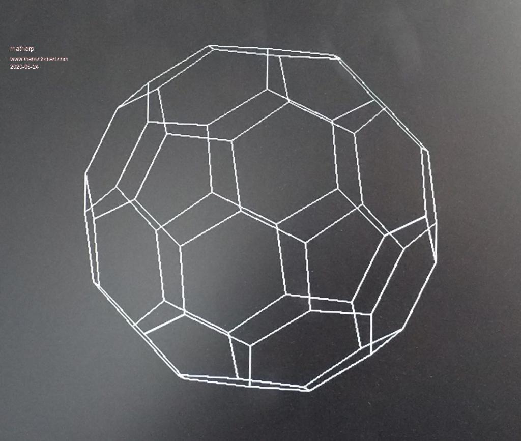 option explicit option default none page write 1 const edgelength=100 'set the length of the verticies of the ticosahedron const zlocation=1000 'how far is the center of the ticosahedron away from us const viewplane=800 'how far is the viewplane away from us dim float x,y,d dim float phi=(1+sqr(5))/2 dim float x1,y1,z1 dim integer col(11), sortorder(11) dim float q1(4),depth(11),v(4), vout(4) ' data for location of verticies for truncated icosahedron of edge length 2 data 0,1,3*phi data 0,1,-3*phi data 0,-1,3*phi data 0,-1,-3*phi data 1,3*phi,0 data 1,-3*phi,0 data -1,3*phi,0 data -1,-3*phi,0 data 3*phi,0,1 data 3*phi,0,-1 data -3*phi,0,1 data -3*phi,0,-1 data 2,(1+2*phi),phi data 2,(1+2*phi),-phi data 2,-(1+2*phi),phi data 2,-(1+2*phi),-phi data -2,(1+2*phi),phi data -2,(1+2*phi),-phi data -2,-(1+2*phi),phi data -2,-(1+2*phi),-phi data (1+2*phi),phi,2 data (1+2*phi),phi,-2 data (1+2*phi),-phi,2 data (1+2*phi),-phi,-2 data -(1+2*phi),phi,2 data -(1+2*phi),phi,-2 data -(1+2*phi),-phi,2 data -(1+2*phi),-phi,-2 data phi,2,(1+2*phi) data phi,2,-(1+2*phi) data phi,-2,(1+2*phi) data phi,-2,-(1+2*phi) data -phi,2,(1+2*phi) data -phi,2,-(1+2*phi) data -phi,-2,(1+2*phi) data -phi,-2,-(1+2*phi) data 1,(2+phi),2*phi data 1,(2+phi),-2*phi data 1,-(2+phi),2*phi data 1,-(2+phi),-2*phi data -1,(2+phi),2*phi data -1,(2+phi),-2*phi data -1,-(2+phi),2*phi data -1,-(2+phi),-2*phi data (2+phi),2*phi,1 data (2+phi),2*phi,-1 data (2+phi),-2*phi,1 data (2+phi),-2*phi,-1 data -(2+phi),2*phi,1 data -(2+phi),2*phi,-1 data -(2+phi),-2*phi,1 data -(2+phi),-2*phi,-1 data 2*phi,1,(2+phi) data 2*phi,1,-(2+phi) data 2*phi,-1,(2+phi) data 2*phi,-1,-(2+phi) data -2*phi,1,(2+phi) data -2*phi,1,-(2+phi) data -2*phi,-1,(2+phi) data -2*phi,-1,-(2+phi) dim float ticos(2,59), nticos(3,59) dim integer i,j,k dim integer xs(179),ys(179),xe(179),ye(179) ' read in the coordinates of the verticies and scale for j=0 to 59 for i=0 to 2 read ticos(i,j) ticos(i,j)=ticos(i,j)*edgelength/2 next i next j 'Find coordinate pairs that are 100 pixels apart dim integer linelist(2,59) for i=0 to 59 k=0 for j=0 to 59 d=sqr((ticos(0,j)-ticos(0,i))^2 + (ticos(1,j)-ticos(1,i))^2 + (ticos(2,j)-ticos(2,i))^2 ) if abs(d-100)<1 then linelist(k,i)=j k=k+1 endif next j next i 'convert coordinates to normalised form for i=0 to 59 x1=ticos(0,i): y1=ticos(1,i): z1=ticos(2,i) create_vector(x1,y1,z1,v()) nticos(0,i)=v(2): nticos(1,i)=v(3): nticos(2,i)=v(4): nticos(3,i)=v(0) next i 'create a quarternion to rotate 2 degrees about a chosen axis 'play with the x,y,z vector which is the sxis of rotation create_normalised_quaternion(2,1,0.5,0.25,q1()) do cls for i=0 to 59 'rotate coordinates v(2)=nticos(0,i): v(3)=nticos(1,i): v(4)=nticos(2,i): v(0)=nticos(3,i): v(1)=0 rotate_vector(vout(),v(),q1()) nticos(0,i)=vout(2): nticos(1,i)=vout(3): nticos(2,i)=vout(4): nticos(3,i)=vout(0) next i ' for every vertex create the lines that radiate from it. This will draw every line twice j=0 for k=0 to 59 x=nticos(0,k)*viewplane/(nticos(2,k)+zlocation)*nticos(3,k)+MM.HRES/2 y=nticos(1,k)*viewplane/(nticos(2,k)+zlocation)*nticos(3,k)+MM.VRES/2 for i=0 to 2 x1=nticos(0,linelist(i,k))*viewplane/(nticos(2,linelist(i,k))+zlocation)*nticos(3,linelist(i,k))+MM.HRES/2 y1=nticos(1,linelist(i,k))*viewplane/(nticos(2,linelist(i,k))+zlocation)*nticos(3,linelist(i,k))+MM.VRES/2 'store the coordinates for a single line command xs(j)=x:ys(j)=y:xe(j)=x1:ye(j)=y1:j=j+1 next i next k line xs(),ys(),xe(),ye() page copy 1 to 0,b loop ' sub create_normalised_quaternion(theta as float,x as float,y as float,z as float,q() as float) local float radians = theta/180.0*PI local float sineterm= sin(radians!/2) q(1)=cos(radians/2) q(2)=x* sineterm q(3)=y* sineterm q(4)=z* sineterm q(0)=sqr(q!(1)*q(1) + q(2)*q(2) + q(3)*q(3) + q(4)*q(4)) 'calculate the magnitude q(1)=q(1)/q(0) 'create a normalised quaternion q(2)=q(2)/q(0) q(3)=q(3)/q(0) q(4)=q(4)/q(0) q(0)=1 end sub ' sub invert_quaternion(n() as float,q() as float) n(0)=q(0) n(1)=q(1) n(2)=-q(2) n(3)=-q(3) n(4)=-q(4) end sub ' sub multiply_quaternion(n() as float,q1() as float,q2() as float) local float a1=q1(1),a2=q2(1),b1=q1(2),b2=q2(2),c1=q1(3),c2=q2(3),d1=q1(4),d2=q2(4) n(1)=a1*a2-b1*b2-c1*c2-d1*d2 n(2)=a1*b2+b1*a2+c1*d2-d1*c2 n(3)=a1*c2-b1*d2+c1*a2+d1*b2 n(4)=a1*d2+b1*c2-c1*b2+d1*a2 n(0)=q1(0)*q2(0) end sub ' sub create_vector(x as float,y as float ,z as float,v() as float) v(0)=sqr(x*x + y*y + z*z) v(1)=0 v(2)=x/v(0) v(3)=y/v(0) v(4)=z/v(0) end sub sub rotate_vector(vnew() as float,v() as float,q() as float) local float n(4),iq(4) multiply_quaternion(n(),q(),v()) invert_quaternion(iq(),q()) multiply_quaternion(vnew(),n(),iq()) end sub |
||||
| matherp Guru Joined: 11/12/2012 Location: United KingdomPosts: 8578 |
Last one of these more as a proof of the absolute performance of the CMM2 than anything useful - 60 vertices, 32 faces full perspective projection using Painter's algorithm to establish face order. Time for each iteration 85mSec despite a huge amount of maths being done  Watch the video 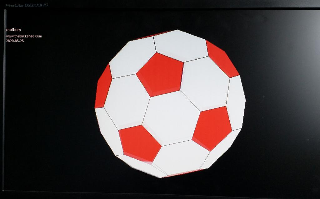 option explicit option default none mode 2 page write 1 const edgelength=100 'set the length of the verticies of the ticosahedron const zlocation=1000 'how far is the center of the ticosahedron away from us const viewplane=800 'how far is the viewplane away from us dim float x,y,d dim float phi=(1+sqr(5))/2 dim float x1,y1,z1 dim integer col(11), sortorder(11) dim float q1(4),depth(11),v(4), vout(4) ' data for location of verticies for ticosahedron of edge length 2 data 0,1,3*phi data 0,1,-3*phi data 0,-1,3*phi data 0,-1,-3*phi data 1,3*phi,0 data 1,-3*phi,0 data -1,3*phi,0 data -1,-3*phi,0 data 3*phi,0,1 data 3*phi,0,-1 data -3*phi,0,1 data -3*phi,0,-1 data 2,(1+2*phi),phi data 2,(1+2*phi),-phi data 2,-(1+2*phi),phi data 2,-(1+2*phi),-phi data -2,(1+2*phi),phi data -2,(1+2*phi),-phi data -2,-(1+2*phi),phi data -2,-(1+2*phi),-phi data (1+2*phi),phi,2 data (1+2*phi),phi,-2 data (1+2*phi),-phi,2 data (1+2*phi),-phi,-2 data -(1+2*phi),phi,2 data -(1+2*phi),phi,-2 data -(1+2*phi),-phi,2 data -(1+2*phi),-phi,-2 data phi,2,(1+2*phi) data phi,2,-(1+2*phi) data phi,-2,(1+2*phi) data phi,-2,-(1+2*phi) data -phi,2,(1+2*phi) data -phi,2,-(1+2*phi) data -phi,-2,(1+2*phi) data -phi,-2,-(1+2*phi) data 1,(2+phi),2*phi data 1,(2+phi),-2*phi data 1,-(2+phi),2*phi data 1,-(2+phi),-2*phi data -1,(2+phi),2*phi data -1,(2+phi),-2*phi data -1,-(2+phi),2*phi data -1,-(2+phi),-2*phi data (2+phi),2*phi,1 data (2+phi),2*phi,-1 data (2+phi),-2*phi,1 data (2+phi),-2*phi,-1 data -(2+phi),2*phi,1 data -(2+phi),2*phi,-1 data -(2+phi),-2*phi,1 data -(2+phi),-2*phi,-1 data 2*phi,1,(2+phi) data 2*phi,1,-(2+phi) data 2*phi,-1,(2+phi) data 2*phi,-1,-(2+phi) data -2*phi,1,(2+phi) data -2*phi,1,-(2+phi) data -2*phi,-1,(2+phi) data -2*phi,-1,-(2+phi) ' 12 faces with 5 sides data 0,28,36,40,32 data 1,29,37,41,33 data 2,30,38,42,34 data 3,31,39,43,35 data 4,12,44,45,13 data 5,14,46,47,15 data 6,16,48,49,17 data 7,18,50,51,19 data 8,20,52,54,22 data 9,21,53,55,23 data 10,24,56,58,26 data 11,27,59,57,25 ' 20 faces with 6 sides data 0,2,34,58,56,32 data 0,2,30,54,52,28 data 1,3,31,55,53,29 data 1,3,35,59,57,33 data 4,6,17,41,37,13 data 4,6,16,40,36,12 data 5,7,19,43,39,15 data 5,7,18,42,38,14 data 8,9,23,47,46,22 data 8,9,21,45,44,20 data 10,11,27,51,50,26 data 10,11,25,49,48,24 data 12,44,20,52,28,36 data 13,45,21,53,29,37 data 14,46,22,54,30,38 data 15,47,23,55,31,39 data 16,48,24,56,32,40 data 17,49,25,57,33,41 data 18,50,26,58,34,42 data 19,51,27,59,35,43 ' dim float zpos(31),zsort(31) dim float ticos(2,59), nticos(3,59) dim integer i,j,k,l,m,n dim integer xs(179),ys(179),xe(179),ye(179) dim integer index(31),nnum(31) ' read in the coordinates of the verticies and scale for j=0 to 59 for i=0 to 2 read ticos(i,j) ticos(i,j)=ticos(i,j)*edgelength/2 next i next j ' dim integer xarr(179),yarr(179) dim integer nv(31)=(5,5,5,5,5,5,5,5,5,5,5,5,6,6,6,6,6,6,6,6,6,6,6,6,6,6,6,6,6,6,6,6) dim integer np(31)=(0,1,2,3,4,5,6,7,8,9,10,11,0,1,2,3,4,5,6,7,8,9,10,11,12,13,14,15,16,17,18,19) dim integer nd(31) dim integer f5(4,11), f6(5,19) dim integer ncol(31) for j=0 to 11 for i=0 to 4 read f5(i,j) next i next j for j=0 to 19 for i=0 to 5 read f6(i,j) next i next j 'convert coordinates to normalised form for i=0 to 59 x1=ticos(0,i): y1=ticos(1,i): z1=ticos(2,i) create_vector(x1,y1,z1,v()) nticos(0,i)=v(2): nticos(1,i)=v(3): nticos(2,i)=v(4): nticos(3,i)=v(0) next i 'create a quarternion to rotate 4 degrees about a chosen axis 'play with the x,y,z vector which is the sxis of rotation create_normalised_quaternion(4,1,0.5,0.25,q1()) do cls for i=0 to 59 'rotate coordinates v(2)=nticos(0,i): v(3)=nticos(1,i): v(4)=nticos(2,i): v(0)=nticos(3,i): v(1)=0 rotate_vector(vout(),v(),q1()) nticos(0,i)=vout(2): nticos(1,i)=vout(3): nticos(2,i)=vout(4): nticos(3,i)=vout(0) next i ' ' average the z positions for the five sided faces for k=0 to 11 zpos(k)=0 for i=0 to 4 zpos(k)=zpos(k)+nticos(2,f5(i,k)) next i zpos(k)=zpos(k)/5 ' index(k)=k next k 'average the z positions for the 6 sided faces for k=12 to 31 zpos(k)=0 for i=0 to 5 zpos(k)=zpos(k)+nticos(2,f6(i,k-12)) next i zpos(k)=zpos(k)/6 ' index(k)=k next k ' sort the z positions sort zpos(),index() ' j=0:m=0 for l=0 to 31 k=index(l) m=np(k) nd(l)=nv(k) if nv(k)=5 then ncol(l)=rgb(red) else ncol(l)=rgb(white) endif for i=0 to nv(k)-1 if nv(k)=5 then xarr(j)=nticos(0,f5(i,m))*viewplane/(nticos(2,f5(i,m))+zlocation)*nticos(3,f5(i,m))+MM.HRES/2 yarr(j)=nticos(1,f5(i,m))*viewplane/(nticos(2,f5(i,m))+zlocation)*nticos(3,f5(i,m))+MM.VRES/2 else xarr(j)=nticos(0,f6(i,m))*viewplane/(nticos(2,f6(i,m))+zlocation)*nticos(3,f6(i,m))+MM.HRES/2 yarr(j)=nticos(1,f6(i,m))*viewplane/(nticos(2,f6(i,m))+zlocation)*nticos(3,f6(i,m))+MM.VRES/2 endif j=j+1 next i next l polygon nd(),xarr(),yarr(),rgb(black),ncol() page copy 1 to 0 loop ' sub create_normalised_quaternion(theta as float,x as float,y as float,z as float,q() as float) local float radians = theta/180.0*PI local float sineterm= sin(radians!/2) q(1)=cos(radians/2) q(2)=x* sineterm q(3)=y* sineterm q(4)=z* sineterm q(0)=sqr(q!(1)*q(1) + q(2)*q(2) + q(3)*q(3) + q(4)*q(4)) 'calculate the magnitude q(1)=q(1)/q(0) 'create a normalised quaternion q(2)=q(2)/q(0) q(3)=q(3)/q(0) q(4)=q(4)/q(0) q(0)=1 end sub ' sub invert_quaternion(n() as float,q() as float) n(0)=q(0) n(1)=q(1) n(2)=-q(2) n(3)=-q(3) n(4)=-q(4) end sub ' sub multiply_quaternion(n() as float,q1() as float,q2() as float) local float a1=q1(1),a2=q2(1),b1=q1(2),b2=q2(2),c1=q1(3),c2=q2(3),d1=q1(4),d2=q2(4) n(1)=a1*a2-b1*b2-c1*c2-d1*d2 n(2)=a1*b2+b1*a2+c1*d2-d1*c2 n(3)=a1*c2-b1*d2+c1*a2+d1*b2 n(4)=a1*d2+b1*c2-c1*b2+d1*a2 n(0)=q1(0)*q2(0) end sub ' sub create_vector(x as float,y as float ,z as float,v() as float) v(0)=sqr(x*x + y*y + z*z) v(1)=0 v(2)=x/v(0) v(3)=y/v(0) v(4)=z/v(0) end sub sub rotate_vector(vnew() as float,v() as float,q() as float) local float n(4),iq(4) multiply_quaternion(n(),q(),v()) invert_quaternion(iq(),q()) multiply_quaternion(vnew(),n(),iq()) end sub |
||||
| CaptainBoing Guru Joined: 07/09/2016 Location: United KingdomPosts: 1985 |
just amazing on both your grasp of this and the abilities of the CMM2 you have written Peter. blows me away to think that the machines this sets out to "copy" were stretched to do this sort of thing in machine code. An Elite/Frontier in MMBasic would appear to be child's play graphically. How I wish I had such a machine decades back. I wrote the processor for a weather radar refurb for Plessey with flight data gathering and later examination of weather radar flight data with rotation in a 3D representation versus balloon height (which sadly they weren't interested in). It was a cow to do as it was all FP in 68K assembler. This would be a walk in the park on such a beast. |
||||
| Paul_L Guru Joined: 03/03/2016 Location: United StatesPosts: 769 |
Andrew ...... was that the 1979 Plessey mini-network system built around a PDP-11/40 installed at the Met Office Radio-Sonde Station, Camborne, Caldwal???? That was an ingenious implementation using the Radar Signal Averaging Unit!!!! BRAVO! Paul in NY. |
||||
| CaptainBoing Guru Joined: 07/09/2016 Location: United KingdomPosts: 1985 |
Hey Paul, you OK? *** warning thread drift, ignore if you want to Plessey had a range of weather radars they gave to meteorological authorities around the globe on condition they got the data for the met office in UK so they could do their charts. 4 flights a day, midday/night and six morning/evening. The WF3 was just such a beast, very basic 60's/70's tech (paxolin tag strips with resistors across and tons of wiring). There was a project (Aladdin) to refit some of them - changes to the head and radome, better electronics and a new microprocessor (Z80) based console replacing the processor which allowed us to modernize the kit and drastically reduce it in size while keeping 100% compatible. Such data was churned out in a standard FM32 PILOT message. Later we added a hardware module for flight data analysis and then PC based - including a very nice version on Amstrad CPC6128s, gutted and embedded in the console... they were a solid, cheap Z80 platform and with memory banking etc. and Floating Point built in the assembler solution was a lot easier to maintain and improve. I wrote all the software for the meto-processing including sonde flights to churn out FM35 TEMP messages for what became the WF33. Sad case that I am, I still have the code! It was these flights, saved to disc, that we later added an analysis module (with Commodore Amigas, gutted and embedded) that gave us the really good 3D projection of the flight as wire-frame. Got praise from Plessey and put the skids under VIZ and Visala (competitors) but ultimately was just seen as a toy by the brass. Shame, it was the dawn of visual analysis and modern systems later did it, we were doing it in 1988, but no conviction from the men with the money. There is a small mention of WF3 (pale blue thing on the end of the bench was the controller we replaced) dunno what processor drove the thing (maybe you can tell from the photo?) and then our WF33 here https://woottonbridgeiow.org.uk/decca-legacy/chapter11.php#11.10 Edited 2020-05-25 22:39 by CaptainBoing |
||||
| Paul_L Guru Joined: 03/03/2016 Location: United StatesPosts: 769 |
I'm fine Andrew. My wife is in the hospital with an infection which has nothing to do with COVID-19 which is well south of us. We live well out in the country 75 miles north of NYC. A half mile east there is a modern dairy farm with 250 Holsteins. Radar equipment generally lasts a long time and there isn't much you can do to improve a magnetron. At Pan Am engineering we had a guy, Bob Ackerly, who was involved in assembling the target radar with linear display which spotted the fleet of aircraft coming to bomb Pearl Harbor but were ignored. Those transceivers on Kauai were still functioning the last time I saw them in 1989! All the improvements come in the signal processing and display areas which was where you were working. I only knew about weather radar through the interfaces we had around the world with local systems. My specialty was the test equipment code for the airborne autopilot and inertial navigation computers. In the 60s we used a punched tape reader to control a Hawker Siddeley Trace ATE which used a PDP11 to test the Bendix PB20B B707 two axis autopilot. The B747 Bendix autopilot test equipment which showed up in 1968 finally got rid of the punched tape reader. The B747 Delco Carousel INS test equipment was controlled by a program read from an IBM 2314 disk about the size of a washing machine which used the 2316 removable disk pack and stored a little less than 30 MB. These gadgets did not use mainstream computer languages. They used hardware dedicated op codes that controlled the airborne computers directly. It was interesting stuff in its day. Paul in NY |
||||
| TassyJim Guru Joined: 07/08/2011 Location: AustraliaPosts: 5899 |
Not a demo - more a test but I had to put it somewhere. This tests the wiring of your 40 way connector. It needs 28 resistors of the same value. I used 200 ohm but anything from 200 to 2k should do the job. It first checks to see if the cable is the right way around. Then we test all digital IN and digital OUT. The analog in is tested by setting one digital OUT high and one LOW to give a voltage at VCC/2. My fist go was on a breadboard then I got creative with the soldering iron. 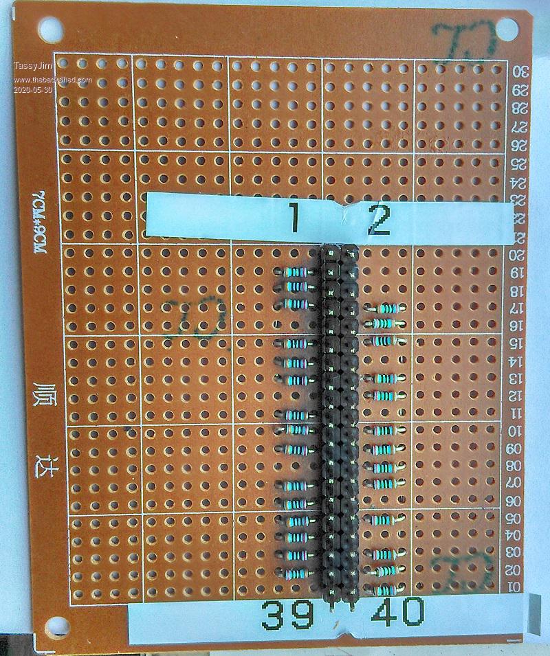 ' CMM2 pin tester. ' requires a bank of 28 same size resistots (I used 200 ohm) ' connected from each pin in pintest() array to a common point DIM pintest(27) = (3,5,7,11,13,15,19,21,23,27,29,31,33,35,37,8,10,12,16,18,22,24,26,28,32,36,38,40) DIM apins(11) = (7,13,15,29,37,8,10,12,16,22,24,26) DIM INTEGER k, bug DIM FLOAT v FOR k = 0 TO 27 ' make sure all pins are floating SETPIN(pintest(k)), OFF NEXT k CLS ' read analog voltage with one pin gnd, all floating then one pin at 3.3V ' header wrong way around will give a narrow range of voltages ~1.16V PRINT "Testing for correct orientation" SETPIN 13, AIN SETPIN 3, DOUT PIN(3) = 0 PRINT "Analog range from ";STR$(PIN(13),2,2);" > "; SETPIN 3, OFF PRINT STR$(PIN(13),2,2);" > "; SETPIN 3, DOUT PIN(3) = 1 v = PIN(13) PRINT STR$(v,2,2) PRINT "A range from 0.2 to 2.9 is good." SETPIN 3, OFF SETPIN 13, OFF IF v < 2 THEN PRINT "It doesn't look right!!" PRINT "Giving up on the tests." ELSE PRINT "Testing Digital IN" ' toggle one pin high/low and check that each pin follows. SETPIN 40, DOUT FOR k = 0 TO 26 testpin = pintest(k) SETPIN testpin , DIN PIN(40) = 1 IF PIN(testpin ) <> 1 THEN PRINT "Pin ";testpin ;" failed DIN high" : bug = bug+1 PIN(40) = 0 IF PIN(testpin ) <> 0 THEN PRINT "Pin ";testpin ;" failed DIN low" : bug = bug+1 SETPIN testpin , OFF NEXT k SETPIN 38, DOUT testpin = 40 SETPIN testpin , DIN PIN(38) = 1 IF PIN(testpin ) <> 1 THEN PRINT "Pin ";testpin ;" failed DIN high" : bug = bug+1 PIN(38) = 0 IF PIN(testpin ) <> 0 THEN PRINT "Pin ";testpin ;" failed DIN low" : bug = bug+1 SETPIN testpin , OFF SETPIN 38, OFF PRINT "Testing Digital OUT" ' toggle each pin in turn and check that output follows. SETPIN 40, DIN FOR k = 0 TO 26 testpin = pintest(k) SETPIN testpin , DOUT PIN(testpin) = 1 IF PIN(40 ) <> 1 THEN PRINT "Pin ";testpin ;" failed DOUT high" : bug = bug+1 PIN(testpin) = 0 IF PIN(40 ) <> 0 THEN PRINT "Pin ";testpin ;" failed DOUT low" : bug = bug+1 SETPIN testpin , OFF NEXT k SETPIN 38, DIN testpin = 40 SETPIN testpin , DOUT PIN(testpin) = 1 IF PIN(38 ) <> 1 THEN PRINT "Pin ";testpin ;" failed DOUT high" : bug = bug+1 PIN(testpin) = 0 IF PIN(38 ) <> 0 THEN PRINT "Pin ";testpin ;" failed DOUT low" : bug = bug+1 SETPIN testpin , OFF SETPIN 38, OFF PRINT "Testing Analog IN" ' testing analog in. ' set one pin high and one pin low to give VCC/2 at the common point. SETPIN 3, DOUT SETPIN 5, DOUT PIN(3) = 1 PIN(5) = 0 FOR n = 0 TO 11 testpin = apins(n) SETPIN testpin, AIN v = PIN(testpin) IF V < 1.58 OR V > 1.7 THEN PRINT "Pin ";testpin ;" failed AIN - ";v : bug = bug+1 SETPIN testpin, OFF NEXT n SETPIN 3, OFF SETPIN 5, OFF IF bug = 0 THEN PRINT "All tests completed with no errors" ELSE PRINT "A total of ";bug; " errors detected over all tests!!!" ENDIF ENDIF This output is with a faulty digital circuit on pin 15. It failed the digital side but passed the analog due to an internal fault in the CPU. Testing for correct orientation Analog range from 0.19 > 1.22 > 2.95 A range from 0.2 to 2.9 is good. Testing Digital IN Pin 15 failed DIN low Testing Digital OUT Pin 15 failed DOUT high Testing Analog IN A total of 2 errors detected over all tests!!! > Jim VK7JH MMedit MMBasic Help |
||||
| lizby Guru Joined: 17/05/2016 Location: United StatesPosts: 3013 |
Are the outer leads of the resistor all ganged? That is what I appear to see through some of the aligned holes. PicoMite, Armmite F4, SensorKits, MMBasic Hardware, Games, etc. on fruitoftheshed |
||||
| TassyJim Guru Joined: 07/08/2011 Location: AustraliaPosts: 5899 |
Yes As per the comments in the code I should have been clearer. In the circuit, the numbers in brackets refer to the pin numbers when the cable is arse about. .png) Jim VK7JH MMedit MMBasic Help |
||||
| matherp Guru Joined: 11/12/2012 Location: United KingdomPosts: 8578 |
' requires a bank of 28 same size resistots (I used 200 ohm) ' connected from each pin in pintest() array to a common point |
||||
| Page 1 of 4 |
|||||
