
|
|
Forum Index : Windmills : 7.5HP Three Phase Motor Conversion
| Page 1 of 3 |
|||||
| Author | Message | ||||
SparWeb Senior Member Joined: 17/04/2008 Location: CanadaPosts: 196 |
When I discovered this motor in the discard pile, I swallowed my pride, and into the bin I went! 
It weighs about 80 pounds, but that's not much more than the 3HP I converted before! Dataplate: Toshiba 7.5 HP 3-phase induction motor 1740 RPM 19.4Amps @ 230VAC, or 9.7Amps @ 460VAC Frame 213T Once I got it open, more good news. A nice big rotor, 12 wires already in the connection box, rear shaft stub with a fan - I couldn't ask for more. Okay, four poles isn't a lot, but I've been noticing that the size and weight of these motors goes up rapidly with the pole count. Why is that? Anyway, four poles works perfectly well. I have a stub shaft for a RPM pick-up, so trying to count pulses on the power line will be a thing of the past. Before cutting anything apart, I started modelling it with FEMM. I like using FEMM both because it gives concrete results that I can use to predict performance, and because it's perrrrty. Here's the FEMM output (GIF is a bit big to fit on this page) Here's the solution when I modeled the conversion of the Toshi using a rotor turned down and flats milled for the 2x1x1/2 magnet blocks. I tried many other magnet combinations, but this worked the best and used magnets that are available. The end view allows me to see the flow of field lines through the stator and rotor, measure peak field intensities (you can find some saturation areas where it's the most pink). Most importantly, FEMM allows you to draw a boundary equal to the span of the windings in the motor, and measure the total flux through the winding. This number, with a bit of number crunching and educated guessing can give you a estimate of open-circuit volts-per-RPM. I also extrapolated the charging current in a 24V battery, but that's taking the guesstimate pretty far... So the forcast is for the mill to reach cut-in for my 24V battery system at about 180 RPM. This should be pretty good for a 10-12 foot prop (a little on the fast side for a 12-footer). 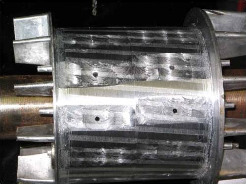
So I put the rotor into the lathe at work and started to turn it down. This rotor's laminations are so thick that there was no risk of removing enough material for the laminations to split apart. A rotor without enough "meat" forces you to make a brand new rotor out of raw materials, or maybe one could press the laminations off the shaft and press on a replacement cylinder. In the end, I cut most of the way through the squirrel cage, but enough material was left to hold the cooling fins on. At the time, I thought the cooling fins were a bonus. How wrong I was! A few more machining steps involved milling the flat faces. You can see that there are two rings of flats destined for two rings of magnets. The offset of the faces will provide an anti-cog skew. As the magnets in each ring are attracted clockwise to the teeth of the stator, the magnets on the other ring will be attracted to counter-clockwise teeth on the stator. That's the theory, and test fitting of the rotor bears that out. (more on that later). Each of the mounting holes are tapped. The holes fit 6-32 NC screws. Obviously one uses stainless steel screws for this job. Steel ones would reduce the strength of the magnets. I had tapped 21 of the 24 holes when I broke the tap in the hole! There was a tiny nub sticking out, which I could grab with the pliers to slowly work the end of the tap out of the hole! That broken tap on the 21st hole was, it turns out, a warning of more trouble to come. Before going too far with the magnets, I put on just four, and put it into the stator to get a "feel" for the de-cogging skew's effect. The rotor turned smoothly, but with a fair bit of resistance. It is called "iron loss", meaning the magnetic field dragging through the iron of the stator requires some force to be overcome. I hope the resistance doesn't scale up by a factor of 6 when I get all 24 magnets on. That could cause a big problem with start-up torque. Anyway, there wasn't much cogging so I satisfied myself with that result, and continued installing magnets. I got to the 20th magnet. The 21st magnet WILL NOT GO ON. 
It took a lot of force, luck, and several tries each to get magnets 12-20 mounted. Previous projects that I have studied on the internet forums, either by zubbly, dinges, or other distinguished experimenters, where many magnets were installed on a single rotor, have all employed rotors made from scratch. I thought I was lucky, having found a rotor where I could use the original laminations and cooling fins! Argghh! 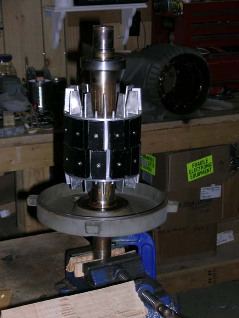
Installing magnets on a rotor without cooling fins is comparatively easy. I did that myself on my first motor conversion. You position the end of the magnet on the edge of the rotor flat, and slide it on. It takes some marshalling because the magnet does want to slide around a bit, but it's not that difficult, especially if you can screw each one down once it's in position. With cooling fins, you either have to tip it up, beside it's neighbours, or push it down flat. All it wants to do, however, is flip over! 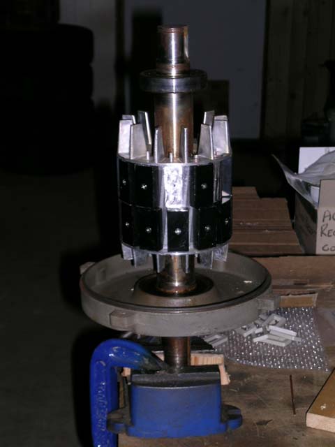
If I can find no way to install the remaining four magnets, I will have to disassemble the entire thing and go back to the shop to remove the cooling fins. I am currently building a tool to force the magnet to remain straight as I force it into place. It's slow going, but I'll let you all know in a few days what does, or doesn't work. Later, guys! Steven T. Fahey |
||||
oztules Guru Joined: 26/07/2007 Location: AustraliaPosts: 1686 |
Sparweb, Try a high tensile rod the size of the magnet/screw holes (maybe 4" long...a skinny philips driver perhaps). Place the rod through the magnet hole and align the rod into the rotor hole.... and push the magnet down the rod until it beds... The most the magnet can do then is spin on the rod... which you will control,  and later will be stopped to a fair extent when you get it below the end rim....clamp it, remove the rod and screw it down..... sounds simple if you say it quickly........ (may need someone to hold the rod/screwdriver while you clamp it and finish the alignment). and later will be stopped to a fair extent when you get it below the end rim....clamp it, remove the rod and screw it down..... sounds simple if you say it quickly........ (may need someone to hold the rod/screwdriver while you clamp it and finish the alignment).
If this scheme works well for you I am happy to take the accolades.... if you get run down by a high speed magnet fleeing the scene.... I've never heard of you, and ... anyway.... I live in a small Nebula on the far side of the Galaxy.... far far away. 
I am a bit non-plussed with the FEMM simulation. The flux lines are just not what I would expect to see. Will be interested in Dinges opinion on this as he has used the program to good effect, and I havent.... but the flux concentrations just don't seem to work for me... like in the wrong places, the bottlenecks where I would expect high flux to be are just not there, and where I expect a non-linear pattern to predominate, it is evenly spread. You must have it in a representation that does not reflect theeee.... no I just don't get it...... I expect to be reprogrammed shortly. .........oztules Village idiot...or... just another hack out of his depth |
||||
| Dinges Senior Member Joined: 04/01/2008 Location: AlbaniaPosts: 510 |
... then I'll blame Dinges ? http://www.fieldlines.com/comments/2007/9/16/25646/5375/3 Good point though, that method should aid immensely when mounting the magnets in your case. Yes, wrestling those bastards in place isn't my idea of fun either. 36 of them on my 10 hp rotor... I was genuinely fearful when I started installing them. Turned out to go better than I expected, but mostly due to the new, full-steel rotor; once the magnet gets close enough to the rotor it attracts itself and stays perfectly put when on it. In your case only half the surface under a magnet is steel, so things may get a little harder... Providing for some excitement and the invention of some new swear words...
Interesting story, Steven. I'm surprized using just 2 magnets per pole, offset by half a slot (I assume that's what you did) is actually enough to nearly eliminate cogging; I would expect it to take at least 3-4 magnets per row, skewed in smaller steps, for it to work properly. I once made a tiny conversion that used just two round magnets per pole, skewed 'to the rules of the book', i.e. by half a slot, but which still cogged slightly. Your results are promising nonetheless. Oztules, I think he's converting it as 4 pole, using 3 rows of magnets per pole. That way he can avoid rewinding. As a 4 pole the magnetic flux lines make sense. If it were mine I think I'd have gone with a 12 pole configuration, but that would have been a lot more work as it requires a rewinding. Looking forward to your updates, Steven, and will be especially interested to see if the real results come close to your calculated values (using the mathematical model you have developed). Peter. |
||||
| oztules Guru Joined: 26/07/2007 Location: AustraliaPosts: 1686 |
Thanks Dinges, That explains it... if I had read properly, then I should have picked that out .
Yes... It is all Dinges fault. .........oztules Village idiot...or... just another hack out of his depth |
||||
| SparWeb Senior Member Joined: 17/04/2008 Location: CanadaPosts: 196 |
Thanks, I was hoping it would be of interest. Dinges: ...and will be especially interested to see if the real results come close to your calculated values (using the mathematical model you have developed). I'm keen to see if it works out, too. I've been bragging about my mathematical prowess for quite a while, now, but I have yet to produce hardware to bear out the theory. You'll be the first to know.
Oz: I didn't explain the FEMM very well. The rotor has 4 poles, and the stock stator is wound that way. To keep the windings as they are, I am putting 4 poles on the rotor. Each pole has 6 magnets, arranged 2x3. That's why you see three magnets with field lines at the top of the FEMM solution that don't connect. They are of the same pole, and the lines collect and travel together through the outer stator to the next pole, 90 degrees away. Struggling with these magnets for hours has made me believe that mounting the magnets, say, as a 12-pole rotor, would be much easier. Mutual repulsion as I push these down is stronger because I am trying to push a N magnet pole between two other N magnet poles. Weighing the work (and potential danger to fingers) of wrestling these magents around against the time required to re-wind one of these things (to increase the pole count) and I'm starting to see another reason to like what Peter did with his 10HP. Cranking a magnet down on a 6-32 threaded rod might work, but it may be too flexible. Thanks for the suggestion. I will try that. Probably didn't consider it before, because it would require two people to make it work. Convincing my wife to help hold on to things may be trickier than manipulating the magnets themselves! Steven T. Fahey |
||||
| SparWeb Senior Member Joined: 17/04/2008 Location: CanadaPosts: 196 |
It worked! I bent one 6-32 rod because I was too impatient to wait for my wife to finish chores and help. Once she was there to crank the nut down as I held the magnet in alignment, things went pretty well. Several magnets are really scuffed up, but the job is done and maybe something like this can be painted. In all the fiddling around, I have now magnetized three screwdrivers, a c-clamp, a pipe clamp, a wrench, several lengths of threaded rod, one pair of pliers, and a pair of wire cutters! Steven T. Fahey |
||||
| oztules Guru Joined: 26/07/2007 Location: AustraliaPosts: 1686 |
Good to see I could help a bit. I now have a lathe chuck that attracts iron particles from everywhere, and a range of tools to match. The chuck is the killer though, gets particles stuck in the spiral race, and seizes it up.... I blame a certain Dutchman for this.... measure the volts/rpm in the lathe.... don't do it. Being a four pole may help keep the inductive reactance component at a much higher RPM than with a 12 pole. Conversely, 12 pole would give you better scope to negate it with capacitors with it's higher frequencies..... why is everything with wind such an inter-related compromise
Sparweb "Okay, four poles isn't a lot, but I've been noticing that the size and weight of these motors goes up rapidly with the pole count. Why is that?" You have to pack in more wire with more poles. Same turns and current for each, but smaller spans.... this of course means more poles packed closer which then adds to leakage between the poles, so they tend to make the rotor larger in diam physically. I think after 12 poles, the leakage flux and slot harmonics is so great they stop (plus the power factor falls away as well), unless you opt for a much larger rotor. I wound a 36 pole induction motor.... got hot and some harmonic crawl, but that was all. With 18 pole a much better crawl, but no real running, with 12 I got it to run reliably, but inefficient, with 8 we were away. .............oztules Village idiot...or... just another hack out of his depth |
||||
| Dinges Senior Member Joined: 04/01/2008 Location: AlbaniaPosts: 510 |
Yikes. That sucks, Oztules. I have plenty of magnetized tools myself by now, every time I visit a machinist friend I take an assortment of screwdrivers, calipers etc. along to demagnetize them on a little gadget he has. Only to find them becoming magnetized soon after when I use them again near neos... But a magnetized lathe chuck... Yikes. That's bad. I never had it happen to me (yet), I'm curious as to how it could have happened to you. The rotorshafts (the ends that stick outside of the case) aren't magnetic in my conversions, so they can't magnetize the chuck. Seriously surprized here. Wonder what you exactly did for it to happen. I ask because that machinist friend now has my 10 hp rotor to turn down the epoxy casting. I certainly wouldn't want anything to happen to his CNC lathe. A magnetized toolpost could be easily remedied, I think (a bit like degaussing a CRT: move the support slowly away from the rotor as it is rotating in the lathe). But the chuck or other sensitive guides... you don't want them collecting metal particles . Makes cleaning impossible. I wanted to ask you about this a few months ago, as I read about this in an old FL story of yours, with Zubbly mentioning something to the effect that it wouldn't work. At the time I wondered whether you actually went through with it and if so what the results were (I didn't find a follow-up post from you on FL but somehow it slipped out of my mind. I'm still toying with the idea of making a 24 or 36 pole conversion some day. I did bounce that idea off Zubbly but he wasn't thrilled; the reason he gave was that rewinding would be practically very difficult (inserting the coils in the slots, as the coil span is very small, only one stator slot); I think I could overcome that problem though; but if there are other, deeper reasons for why it wouldn't work... of course, induction motors are asynchronous whereas our conversions are synchronous... no squirrel cage rotor and slip... so it may not be a problem in conversions. Or ? |
||||
| oztules Guru Joined: 26/07/2007 Location: AustraliaPosts: 1686 |
Dinges, Check it out on your femm. The only problem I see is the inter pole leakage. If your airgap is very small, this may help alleviate that a bit, but the physical segregation of fields could be a problem to look at. Try simulating different air gaps. The other major concern would have been inductive reactance issues bought on early from the higher frequencies..... but these very recently seem to be seen as a bonus rather than a curse.... interesting how the world has changed in the past few days.... even the curse of resistance may be partially mitigated with the Q .........oztules Village idiot...or... just another hack out of his depth |
||||
| SparWeb Senior Member Joined: 17/04/2008 Location: CanadaPosts: 196 |
[quote]...I now have a lathe chuck that attracts iron particles from everywhere...[/quote] That must be awful. For another way to de-magnetize your chuck (maybe) you could try to find an aircraft parts inspection company, particularly one that inspects helicopter parts. Large operators often equip themselves to do the inspetion in-house, too. They would have rather large equipment for "degaussing" parts after their magnetic particle inspections. A regular lathe chuck would fit in them. Show them some pictures of the crazy stuff you do - guys around here would help you out for free if you asked. I can propose a way that the lathe chuck would be magnetized. While holding the rotor in the lathe, did you install or remove magnets from the rotor? If so, the unbalanced fields would leave extra field lines from one pole that would spread into space, and into the nearest big hunk of metal they can find. The circuit completes through the jaws of the chuck, to the shaft, and back into the rotor. The tailstock and toolrest may also be magnetized. Earlier, when I was experimenting with the cog, and had only a couple of magnets on it, I had a lot of trouble inserting the rotor into the housing. It was sticking magnetically to the end shells. I realized that I had placed all of the magnets N pole out. The ends of the shaft were big S poles! The loop must be closed between all of the rotor's poles, or the lines can "wander". The rotor on my bench is complete, but there still seems to be some stray field lines because I can pick up washers and screws with the end of the shaft, now. The rotor may not be keeping the lines inside the laminations, or it may have something to do with putting 4 inches of magnet on a stack of laminations only 3.8" across. Steven T. Fahey |
||||
| GWatPE Senior Member Joined: 01/09/2006 Location: AustraliaPosts: 2127 |
Hi sparweb, What purpose do the cooling fins have on the rotor now? They were there on the original design to dissipate the energy produced by current from the squirrel cage and the hysterisis in the iron core. None of that happens with permanent magnets. Gordon. BTW I passed up the opportunity of a 5.5kW 720RPM motor. This would probably be good as a conversion. become more energy aware |
||||
| SparWeb Senior Member Joined: 17/04/2008 Location: CanadaPosts: 196 |
Good question Gordon. True, there's not much need to cool the rotor. The stator may benefit from the extra airflow, though. My main reason for keeping the fins on is that they keep the rotor laminations together. That last time I turned a rotor down (for someone else's project), once the rotor had been turned down so far that the fins were cut off, the individual laminate disks started to spread apart. The person I was doing this for decided to bolt them back together through a set of lightening holes that were available. This rotor here doesn't have any lightening holes, so if the laminations started to separate, that would be the end of it - I would end up removing them all and making a new big cylinder to replace them. Admittedly that would give a better return path for magnetic flux... but lots of pain for little gain, really. So it's actually a structural reason, more than anything else. I won't take you up on the 720 RPM motor: I already have one and it weighs twice as much as this 4-pole motor! Steven T. Fahey |
||||
| GWatPE Senior Member Joined: 01/09/2006 Location: AustraliaPosts: 2127 |
I would not remove them completely, only 95%, just leave a stub. Gordon. become more energy aware |
||||
| johnj Newbie Joined: 05/04/2008 Location: DenmarkPosts: 17 |
Hi evrybody, Im trying to make a conversion of a 3 phase motor. Im getting desperate as I cant figure out how to find the number of poles in my motors, Please can you go to http://www.vawts.net/index.spark?forumID=125317&p=3&topicID= 24201216 and see what Im doing wrong? Thanks cheers, J |
||||
| Janne Senior Member Joined: 20/06/2008 Location: FinlandPosts: 121 |
johnj, you can get the number of poles your original winding has by looking into rater RPM's. Because where you live the grid frequyncy is 50Hz, it means that a 2 pole motor is rated at 3000rpm, 4pole at 1500rpm, 6 pole at 1000rpm, 8 pole at 750rpm etc.. the link you posted to another forum doesn't work, at least for me. If at first you don't succeed, try again. My projects |
||||
| johnj Newbie Joined: 05/04/2008 Location: DenmarkPosts: 17 |
http://vawts.net/index.spark?forumID=125317&p=3&topicID=2420 1216 Thanks Janne this really helped. Ive tried to post a link again. Does this mean: 920 rpm gives 6 poles, so I place 6 or 12 rows of magnets on my rotor. 12 rows of narrow magnets will give power at lower rpm. or 6 rows of wide magnets will give more power but at higher rpm. Still I dont get the idea of 18 coils in stator. cheers, J |
||||
| johnj Newbie Joined: 05/04/2008 Location: DenmarkPosts: 17 |
Link doesnt work, try this http://vawts.net/ look for 3-phase motor Best wishes, J cheers, J |
||||
| Dinges Senior Member Joined: 04/01/2008 Location: AlbaniaPosts: 510 |
John, The link doesn't work for me either. A few weeks ago someone else asked the same question, see the link below: http://www.thebackshed.com/Windmill/FORUM1/forum_posts.asp?T ID=1448&PN=1 If you know the nameplate speed of the motor (RPM), then number of poles = 6000/RPM. Peter. |
||||
wdyasq Newbie Joined: 29/07/2008 Location: United StatesPosts: 21 |
Interesting discussion, I am glad the Dutchman has been identified as the real problem. Years ago I built my own demagnetizer by taking an old motor core and just plugging it in. Tools are placed in the 60Hz field and slowly drawn out. It worked for me. Ron Adventure is just bad planning." -- Roald Amundsen |
||||
| oztules Guru Joined: 26/07/2007 Location: AustraliaPosts: 1686 |
Ron, It was all Dinges fault as usual, and I had to split a microwave transformer to make the degausser. I cut the "I"'s from the "E"'s so had the e core with the primary on it. It gives a very very strong directional field. Because the inductance is so low without the I's, I used a 40v transformer to drive the 240v primary. I now have demagnetized the chuck and all associated tooling... and am damn pleased too. ...............oztules Village idiot...or... just another hack out of his depth |
||||
| Page 1 of 3 |
|||||
