
|
|
Forum Index : Solar : PV Over Voltage Limiter
| Author | Message | ||||
Haxby Guru Joined: 07/07/2008 Location: AustraliaPosts: 419 |
Mike, if you are going with fixed loads, with 100w increments, I'd suggest each load to be 100w more than the previous. Just switch in what you need. Less hardware that way. So: 100w element 200w element 300w element Etc. So just with the 3 elements above you can select 100,200,300,400,500,600 watts of load. |
||||
| Solar Mike Guru Joined: 08/02/2015 Location: New ZealandPosts: 1125 |
Good idea, I'm not sure how much power I will need to dissipate in order to reduce the peak unloaded - light loaded VPeak to a lower value; if say 6KW array; will have to do some experimentation. Cheers Mike |
||||
| Warpspeed Guru Joined: 09/08/2007 Location: AustraliaPosts: 4406 |
Or you could use: 100 watt element 200 watt element 400 watt element Switch in binary so you get 100 watts to 700 watts in 100 watt steps, with only three resistors and three mosfets. A cheap and cheerful analog to digital converter chip maybe ? Cheers, �Tony. |
||||
| pd-- Senior Member Joined: 11/12/2020 Location: AustraliaPosts: 122 |
Or go old school wind the nichrome wire on a old terracotta pipe mount a starter motor brush on a threaded rod so that the brush contacts the wire and its position can be varied by rotating the threaded rod You can do the same trick with the elements from old two bar radiators and sum copper braid and phosphor bronze springs to act as your wipers |
||||
| brucedownunder2 Guru Joined: 14/09/2005 Location: AustraliaPosts: 1548 |
Gee, check out the search section. I remember this DIY gadget was discussed and documented. Many years back. So grab a drink and see if you can find it . I even started to build a huge one with finned heater lengths . Still have them ,and was thinking the other day of making something to test solar panels for their condition. Bruce Bushboy |
||||
| Solar Mike Guru Joined: 08/02/2015 Location: New ZealandPosts: 1125 |
That is old school.., but to make this respond in a dynamic fashion to changing light levels and load on the panels from the charge controllers, I have to design something to turn the threaded rod... seems too much work. |
||||
| Solar Mike Guru Joined: 08/02/2015 Location: New ZealandPosts: 1125 |
Decided to start to build up something, did few tests putting a 1 amp load on unloaded 1.5Kw 120v panel array that's close at hand, the voltage dropped 7-8 volts; so should work on a 200V peak array. Simplest I can come up with is 8 comparators that have push-pull outputs, that will concurrently switch on as their sample voltage increases over a narrow range. Each one turns on a mosfet with a 500 Ohm alclad resistor bolted to a heatsink. May have to have a small fan, will see, I don't like fans, they crap out after a number of years, longest I have had one run for is 2 years before the ball bearings fell apart. Circuit: 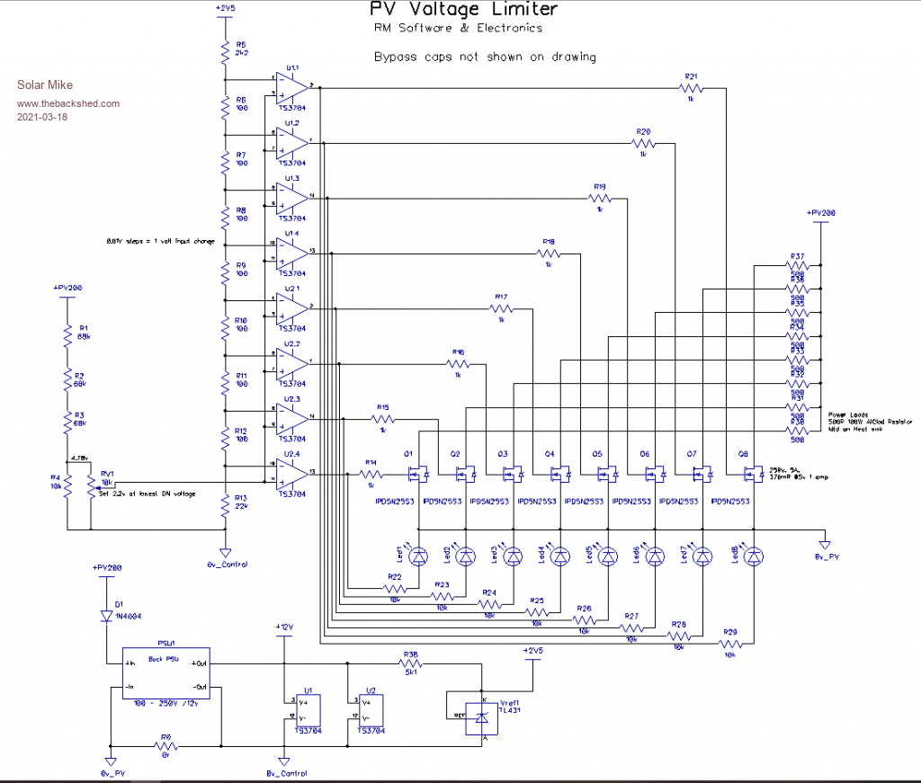 Note no bypass caps shown, or spike protection but will be on the pcb. Cheers Mike |
||||
| Solar Mike Guru Joined: 08/02/2015 Location: New ZealandPosts: 1125 |
100 x 100mm PCB, circuit essentially unchanged other than component designators have altered after I re-numbered the old schematic above. The specified DPak mosfets are rated for 250v, 5A, Rds of 0.33R at 2A load; the pcb trace acts as a heatsink, so should be ok for loads under 3A per device or 24A total. I have a box of 1000R 50W resistors and will use combinations of them bolted to a 3mm thick alloy plate as the heatsink. The plan is to set the sense voltage some what above the array Mppt value, so when the PV is lightly loaded the mosfets start turning on, applying a load to limit the peak voltage. I haven't placed any spike suppression on the mosfets, their turn on/off speed will be limited by the drive resistors, so unlikely to cause high speed transitional glitches. Guess you could also use something like this on a wind powered device to add additional loading if the speed increased and thus higher voltages.  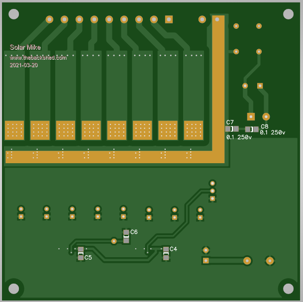 Cheers Mike |
||||
| Warpspeed Guru Joined: 09/08/2007 Location: AustraliaPosts: 4406 |
Very nice Mike, an excellent job as usual. Be very interested to see how this goes. Cheers, �Tony. |
||||
| Solar Mike Guru Joined: 08/02/2015 Location: New ZealandPosts: 1125 |
Not sure how this scheme will work when used on our large 6Kw array, seems I may require a lot of 50W resistors and an enormous amount of heat. Would be nice to put this heat somewhere - a hot water cylinder ??. Thinking back to the discussions on powering a HWC element from a PV array... One big resister (3-4KW) element and a 300V mosfet with PWM, working on the principle of when the array voltage exceeded a lower threshold, start PWM drive to mosfet with small duty cycle, if the PV voltage continues to increase then increment the duty cycle proportionally placing a larger average load on the heating element. Bit like a very simple buck regulator + inductor but not many bulky capacitors. Will draw a circuit... Mike |
||||
| Warpspeed Guru Joined: 09/08/2007 Location: AustraliaPosts: 4406 |
Back in 2018 I built a simple continuously adjustable load for testing and comparing solar panels. It used an LM555 timer that generated pwm 0% to 100% duty cycle, and that switched a very heavy resistive load on and off that discharged a large electrolytic.  The electrolytic was large enough to completely eliminate the pwm pulsing, and acted as a steady state load on the single 24v solar panel (one only). Not really a buck converter as there was no choke, it just switched the resistive load on and off. A choke would have been better, and greatly reduced the size of the electrolytic needed, but for this I did not bother with a choke. It used a Turnigy power meter that monitored volts, amps, watts, and watt hours. Very instructive on how solar panels actually behave, and it is also what led me to the original idea of the "solar hot water" self adjusting MPPT controller. Cheers, �Tony. |
||||
| Solar Mike Guru Joined: 08/02/2015 Location: New ZealandPosts: 1125 |
That looks highly original Tony, those little watt meters are great, I use one for testing low voltage PV controller outputs. Here is a brief schematic, sort of works in reverse to a standard PWM buck power supply controller in that only the input PV is monitored, if its less than a set point, say 6 volts above the normal expected PV mppt value then it switches off any pwm drive and does nothing. When the PV input exceeds the setpoint, then pwm drive starts with 1-2% duty cycle and increases proportionally to any voltage increase, ie. to prevent the PV voltage from increasing too much, the wasted power heats up the water. During normal operation the PV charge controller is running at the PV array mppt point, so the load circuit wont have any affect; it will only switch in if the voltage rises say when on float or similar. If I allow up to 20 amps of load current that should be sufficient to keep the voltage under control, any more then that may have to use a synchronous mosfet rectifier rather than the MBR40250. No large electro's on the output as I dont really care about any ripple. 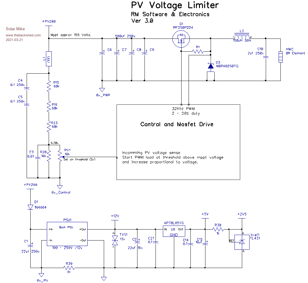 Cheers Mike |
||||
| Warpspeed Guru Joined: 09/08/2007 Location: AustraliaPosts: 4406 |
If you put the mosfet in the negative side, the source could then be grounded, which makes it a lot easier to drive. Cheers, �Tony. |
||||
| Murphy's friend Guru Joined: 04/10/2019 Location: AustraliaPosts: 584 |
I always admire your PCB's Mike, one could learn a lot from them. To further my knowledge, can you supply more detail on that nifty way to pass heat (and current) from one side to the other by using multiple tiny vias? Specifically, what size drill for those vias and how much current each can handle. If there is some online calculator for plated through hole current capacity I'd appreciate a link to it. I assume that capacity depends on the size of the plated through hole? |
||||
| Warpspeed Guru Joined: 09/08/2007 Location: AustraliaPosts: 4406 |
Many years ago when we still had companies in Australia manufacturing circuit boards, I remember a discussion with the factory production manager. He said they did some testing of plated through holes and especially vias as to how much current they could take, and about two amps per via was about the practical limit, as I recall. You can place non tented vias as very small normal pads (or pads within pads), which means the via is not covered by the solder mask as they normally are. The vias can then be filled with solder which should make a big improvement to both heat and current transfer. As far as heat dissipation, about one watt per square inch if both sides of the board are used seems to be about the limit, although I have never seen any published recommendations. Anything in contact with a board that reaches 80 Celsius or more will make the board turn black over time. Cheers, �Tony. |
||||
| Haxby Guru Joined: 07/07/2008 Location: AustraliaPosts: 419 |
Lots of interesting tricks in the trade for heat dissipation these days. Here is a tesla Powerwall MOSFET board: I think it uses IRL7472L or similar package. 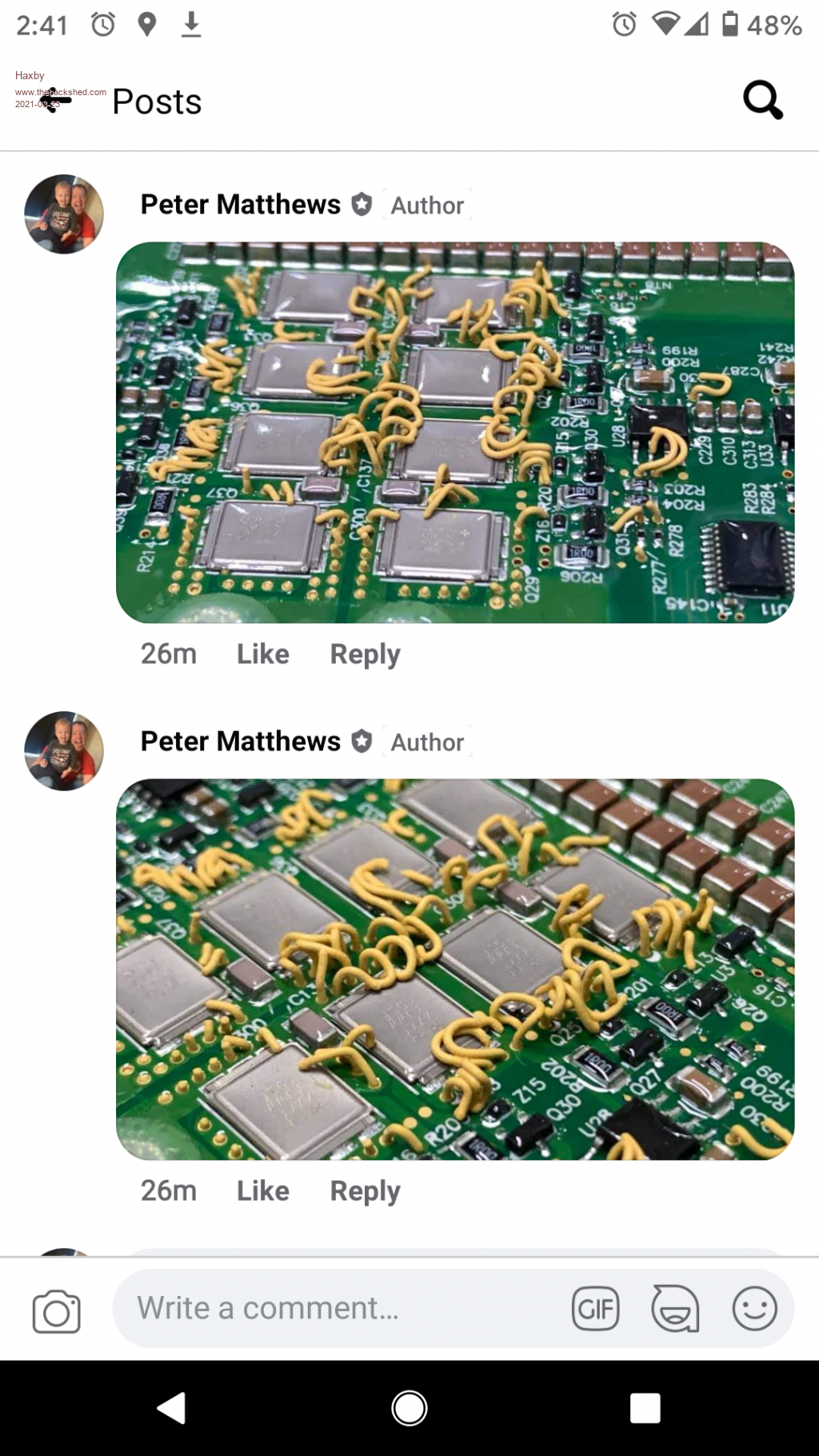 Looks like the whole board is stuck down with a thermal adhesive and the vias stop air bubbles from forming in the adhesive during manufacture. The result is the Raman noodles look. There are also smd components that look like capacitors but all they do is transfer heat from one pad to another. Good to use when you have a giant ground layer heat sink but the component you want to cool is floating at some voltage. |
||||
| Solar Mike Guru Joined: 08/02/2015 Location: New ZealandPosts: 1125 |
Hi Murphy's friend. Thanks for the kind comments. Standard 1.6mm FR4 cored pcb doesn't conduct heat well, placing open un-tented 0.4 to 0.5mm vias that allow flow soldering to fill them up will improve things a lot. It can never be as good as bolting the power device direct to a heatsink, going to thinner 0.8mm pcb material would allow a better heat transfer. Better the new alloy cored pcb materials. The pcb I'm using here has 16 x 0.4mm vias on the drain of each mosfet, pcb will be 1mm thick, each mosfet will only be dissipating 0.35W @1A to 1.4W @2A, so temperature rise isn't really an issue, current carrying capacity of vias is determined by the surface area and depth of the plated through hole and allowed temperature rise, 0.4mm vias can conduct several amps, I allow 1amp per via to stop them warming up to much. One of the high power PV controllers in a previous design has DPak power devices soldered to the top of the board, with the heatsink mounted via an insulator bolted to the underside, each device has 42 x 0.5mm vias linking each layer, how this will work in practice I dont know, building those up now, still waiting for the mosfets to arrive... Here are some links for PCB trace\Via calculations Calc1 Calc2 Cheers Mike |
||||
| Solar Mike Guru Joined: 08/02/2015 Location: New ZealandPosts: 1125 |
Very true, I need to have another think about this concept overall. Initially the aim was to reduce the peak array voltage of approx 200v when the panels were unloaded down to 160v, 5 volts higher than the mppt value of 155. Then later thinking to divert this wasted power into something more useful other than heating up the air. A standard HWC element (3Kw 17.6R) could be used, however at the 160v value only 1500W would be used, when the 6Kw array could pump out a lot more. Would have to use 2 elements in parallel to lower the resistance, I don't really want to weld another big nut onto the cylinder in order to add a second element. Perhaps a simple high frequency transformer pwm push-pull inverter could be used to step up the voltage from 160 to 230, rectified and the unfiltered pulsing DC supplied to the element via a switch device connected to the thermostat. Or a boost upconverter topology....... Cheers Mike |
||||
| Boppa Guru Joined: 08/11/2016 Location: AustraliaPosts: 814 |
One point to remember with solar panels is that the output rating is at a specific temperature and illumination level only- add recent rain on a cool day, with sunshine through a break in the clouds on an an overcast day- if isn't uncommon to get a 30% or more increase over the 'rated' output.... :-O (Installers are well aware of this, and experienced ones will spec to suit, keeping well away from both the voltage and current limits of the controller.... look up 'cloud effect' or 'fringe effect' to see more... |
||||
| Solar Mike Guru Joined: 08/02/2015 Location: New ZealandPosts: 1125 |
Thanks for the comments, fully aware of that, my situation is am testing out many different DIY controllers on the same PV array, some higher voltage rated than others, the limiter is to make such testing easier. Will be keeping the simple design using resistors to keep max upper voltages within limits, currently cannot get the mosfets, keep getting pushed back on back order. For the larger multi KW 200 volt arrays, have decided to build something to allow diversion of power into a hot water cylinder element, when the PV controller starts throttling back as batteries charge up, the diverter device will seamlessly load up the PV, converting DC into a 50Hz AC square wave to supply the element; will post a new topic on this soon. Cheers Mike |
||||
