
|
|
Forum Index : Electronics : all home built solar system
| Author | Message | ||||
| poida Guru Joined: 02/02/2017 Location: AustraliaPosts: 1388 |
Nicks, nano2 code is not very time critical at all. It checks a few analog inputs, makes a few calculations, checks a digital input and runs or stops the inverter. Your changes will work fine. I would expect: client sends ^12 (and a newline character) to nano2 nano2 replies with the data, dcv, comma, aci, comma etc. wronger than a phone book full of wrong phone numbers |
||||
mason Regular Member Joined: 07/11/2015 Location: CanadaPosts: 86 |
Hi Peter, just wondering if there is a 60hz version of your code for the picoinverter, I might build a couple just for the fun of it. Thanks |
||||
| poida Guru Joined: 02/02/2017 Location: AustraliaPosts: 1388 |
Easy to do Mason. change one line. was #define PPWM 800 // 50.002 Hz 799 49.939 Hz for 800 to #define PPWM 665 // 60.062 Hz in pico_2_heavy_filter_bv.ino.zip The serial data produced for the LCD (if used) will now be nothing like 9,600 baud. Probably (10,000 * 6/5) baud whatever that is. I just tried it a moment ago:  wronger than a phone book full of wrong phone numbers |
||||
| mason Regular Member Joined: 07/11/2015 Location: CanadaPosts: 86 |
Great, thanks again Peter |
||||
| iannez Newbie Joined: 05/07/2019 Location: ItalyPosts: 23 |
Hello everyone! Thanks to Peter (Podia) for sending me some pictoverter PCBs and for all support offered in private messages! I finally managed to set up a test bench using the picoverter loaded with the Nanovariac firmware so I can vary through potentiometer the output voltage to check a few things, I'm not using feedback for now. I use a power supply to power the picoverter with a DCDC Converter 24V => 15V and to enter direct in AliExpress inverter. I'm using an Aliexpress 24V inverter as a power board. In the picture you see everything including waveform with mini DSO. 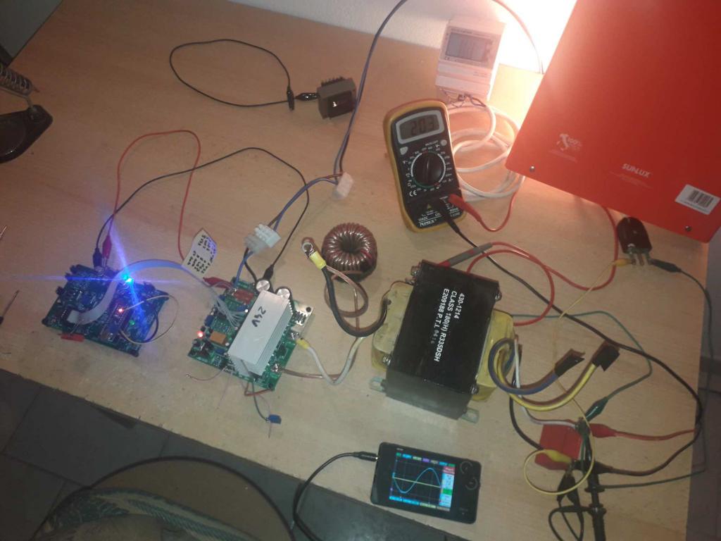 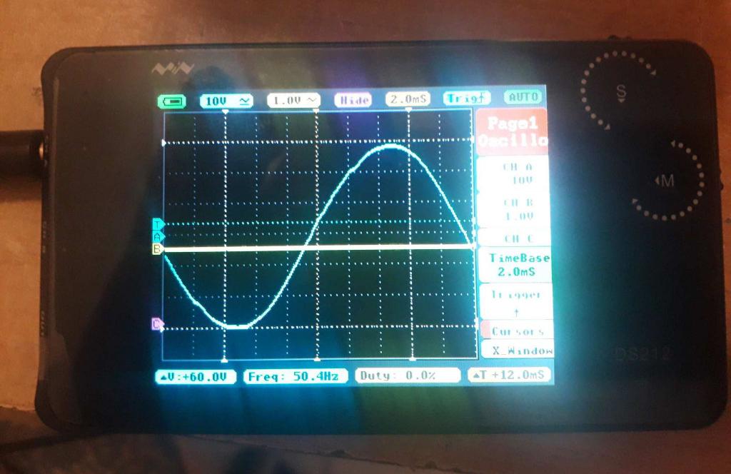   The DMM scores about 200V because under load the tension drops a little bit and also because I didn't want to go beyond at this test phase. Always in photos behind the DMM we see distortion at about 2.78% on the voltage. I would have expected less than 1%. I also used an inductance formed by three ferrite rings with a bit of a spire of cable in series with the primary of the transformer. The transformer was of a dead UPS. It's big enough, I respect 500W. On the secondary side HT I used a 2.2UF WIMA capacitor. I would have asked you some questions ... - Is it normal that with a load of less than 100W of bulbs after about 15min enough warmer is the inductance and the transformer while the inverter heat sink remains cold? - How can I estimate the best DC voltage to understand if the transformer is working properly? - same thing with the inductance and exit capacitor, as I can have a feedback on filtering efficiency / exchange with the transformer? I am afraid that the transformers from UPS are not properly sized as windings / flow to provide continuously a few watts while maintaining a good outgoing waveform. Thanks for the advice, see you soon A. Edited 2021-09-04 01:22 by iannez Cheers, Angelo |
||||
| poida Guru Joined: 02/02/2017 Location: AustraliaPosts: 1388 |
Hi Angelo The UPS transformer is going to be inefficient and spend a good number of watts just heating the core. It will work, for sure, but it will get warm. That is the nature of IE type transformers that are built to a low cost. wronger than a phone book full of wrong phone numbers |
||||
| johnmc Senior Member Joined: 21/01/2011 Location: AustraliaPosts: 282 |
Pico inverter problems Good day all , I have been able to upload the nano program nano_1_v7_no_bessel.ino.zip the sketch verified and loaded with out error and generates a 15v pulsed out put to the IR2184 chips on pin 4. As this is a earlier nano program will it still run the pico inverter controller? The reason I ask is that I can not verify and upload the later firmware pico_2_heavy_filter_bv.ino.zip and pico_1.ino.zip with out a error notice. As I do not know how to save these error messages to post, for that matter I know almost zero about arduino nano. I am using Arduino version 1.8.16 may be this is the fault? Any advice will be most appreciated . Cheers john johnmc |
||||
| iannez Newbie Joined: 05/07/2019 Location: ItalyPosts: 23 |
Hello John. I have now tried to fill out with Arduino 1.8.16. And everything works properly. The sketch pico_2_heavy_filter_bv does not use external libraries because not use lcd or other. it's a simple version of the nanoverter created by Podia. So if you have a mistake during compilation or during upload could be that you have some settings wrong in the IDE of Arduino. You can copy a possible error by making the copy paste on the writings of the Arduino box. You can try to enable debugging from Arduino IDE settings. bye Angelo. Cheers, Angelo |
||||
| poida Guru Joined: 02/02/2017 Location: AustraliaPosts: 1388 |
I'm not at home (holiday location..) so it's all from memory. There are 2 types of Nanos. Both types needs a setting for uploading to work at all. pico_2_heavy_filter_bv WILL compile when you choose board: Arduino Nano Uploading is dependent on which type of Nano you have. from the menu, processor: ATMega328 or processor: ATMega328 (old bootloader) It can be a pain to work out which one you need to use but once you know, it's reliable and easy a trap: if there are two copies of the .ino file in the directory and you double click to load one of them you will find it will not compile. Delete the extra file and try again. The Arduino IDE needs the .ino file to be inside a directory named the same. eg: a folder named "pico_2_heavy_filter_bv" is to contain a file named "pico_2_heavy_filter_bv.ino" wronger than a phone book full of wrong phone numbers |
||||
| johnmc Senior Member Joined: 21/01/2011 Location: AustraliaPosts: 282 |
Good Day, Angelo and Peter,thanks you both for the help. poida said,,, a trap: if there are two copies of the .ino file in the directory and you double click to load one of them you will find it will not compile. Delete the extra file and try again. Problem 1 done that!! The Arduino IDE needs the .ino file to be inside a directory named the same. eg: a folder named "pico_2_heavy_filter_bv" is to contain a file named "pico_2_heavy_filter_bv.ino" Problem also done that !! After much trial and error Firmware compiles and loads and the controller tested ready, and after xmas, I will fit to my repaired inverter. Many Thanks and best wishes to all for Xmas. cheers john johnmc |
||||
| johnmc Senior Member Joined: 21/01/2011 Location: AustraliaPosts: 282 |
Good Day all, I have built a oz inverter lasted 2 years then it blewup destroying most of the electronics. Then I built a larger 8kw Mad / oz inverter it lasted 3years , and most pleased with it. Alias it fizzed and passed away last novemeber 21. Since then I have tried in vain to build a Poida nano inverter. The first two smoke out events I was able find that I had made errors . The next 3 smoking events I do not know why. I believe that the instructions have been followed. I have been using nano_1_v7_no_bessel.ino.zip firm ware. As I have not been able to load the current firmware pico_2_heavy_filter_bv.ino.zip with out a uploading and verify error The output from the control board to the power board is I believe as shown on the forum notes. The shell shock happens instantly, when I connect the transformer into the system and add power even though the inverter is not turned on. I have tried two different transformers, all new boards and controls . I believe that the nano has uploaded with out a uploading error, but I have no idea how to verify the the upload. But it uploads the simple digital flashing diode sketch and the light flashed All suggestions most welcome including packing it in. cheers john johnmc |
||||
| Warpspeed Guru Joined: 09/08/2007 Location: AustraliaPosts: 4406 |
Its highly likely that the gremlin is not in the software but the hardware. Highly stressed parts just finally spit the dummy. And when one mosfet expires, all its close mates end up a smoking ruin as well, without any clues remaining as to what let go first. PWM is excellent at low to medium power, where you can get away with having very few mosfets per leg. Its much easier to get good balance and a symmetrical physical layout with only (say) two mosfets per leg, eight in total. Where you have say five mosfets in parallel per leg, they may not current share particularly well, and the first one to turn on, and the last one to turn off cop most if not all of the switching stress. Its not as simple as saying 4 mosfets in a bridge will produce 2Kw reliably, so twenty mosfets should give me 10Kw of indestructible power very easily. The best developed software in the world cannot solve this problem. PWM just does not scale up to very high power easily. If you really need 8Kw reliably, high frequency PWM is going to be very difficult. Not impossible, but a very serious challenge. That is the Reason for the Warpverter. The largest inverter switches at only 50Hz, and layout is far less critical. The difference between switching at 50Hz and 20Khz is 400:1 About the same as the difference as walking speed, and a fighter jet breaking the sound barrier. Everything becomes much less critical, and reliability at really high power much easier to achieve. PWM is the obvious logical choice up to probably four to five kilowatts. Beyond that it becomes much more diffiult. Cheers, ĀTony. |
||||
| Murphy's friend Guru Joined: 04/10/2019 Location: AustraliaPosts: 583 |
Sorry to read about your inverter misfortunes but I can assure you that membership to the inverter blowup club requires a few 'spark and bang' events   . You are most welcome now . You are most welcome now  . .Anyway, as Tony says, its most likely a hardware problem. The original OZinverter has had an occasional shoot through problem. Unfortunately the 'mad'inverter with its totem pole driver did not eliminate this. I have built both of them (but using my own PCB's) and had (club membership ) problems.Then I built the opto isolated nano inverter but using a totem pole driver based on wiseguy's ideas and that has been trouble free in both, a 3KW and a dual stack core 6KW version. I have a warpinverter too, its a novel design that works well but its also rather complex (and expensive) compared with a single transformer inverter. You either have to like (enjoy) winding 4 transformers by hand or pay somebody to do it for you before I would suggest you tackle one. How do you control the massive inrush currents of the big capacitors of your inverter? They *must* be slowly fully charged before you turn the nano control board on. And no AC load present at that time. |
||||
| noneyabussiness Guru Joined: 31/07/2017 Location: AustraliaPosts: 506 |
warp, i would respectfully disagree, mine had not missed a beat in over 3 years, has consistently seen over 9kw... yes, things can become more " difficult " when you start getting up in power, and in no way am i disrespecting your warpinverter design, however this issue i do agree it may be hardware related, once the system is setup, it is almost bullet proof... suggestion would be to buy a pre-built board AU $259.77 8%OFF | 24V 5600W 36V 8600W 48V 12000W 60V 72V 96V 19000W Foot Power Pure Sine Wave Power Frequency Inverter Circuit Board A Main Board https://a.aliexpress.com/_mrrQwQo something like this... saves a lot of headaches if you don't know what you are doing... anyhoo, best wishes with it I think it works !! |
||||
| InPhase Senior Member Joined: 15/12/2020 Location: United StatesPosts: 178 |
I built a prototype nanoverter and it worked very well in the limits of my testing. But not before I smoked it once or twice. To start troubleshooting this, I suggest you disconnect the control board completely. Use a continuity tester to verify there are no shorted mosfets. Apply power to the board with no control and see if it behaves normally. What I found in one case is that the ir21844 driver chips weren't turning the FETs all the way off and this was apparent even with no control board. Hook up the 'scope and check those outputs. There are many more points to check, but that is a start. Edited 2022-01-12 02:26 by InPhase |
||||
| johnmc Senior Member Joined: 21/01/2011 Location: AustraliaPosts: 282 |
Good Day All Thanks for the replies and the different options that I had not thought about. For the moment I will let my enthusiasm recover and then decide.  Cheers john johnmc |
||||
| Warpspeed Guru Joined: 09/08/2007 Location: AustraliaPosts: 4406 |
Its certainly not an easy decision. Off the shelf Chinese is certainly one way, but the advertised 16000000 Chinese advertised watts need to be taken with a grain of salt. Off the shelf super expensive name brand inverter, may not be much better...... Home brew some version of the original Oz inverter. HIGHLY RECOMMENDED for most people, but the success/results seem to vary a lot. I have no idea why that is so. Warpverter, expensive and a LOT of work to build. However, apart from one unlucky poster here, every single one built worked very first attempt without any subsequent problems. I believe there are now about sixteen Warpverters in reliable operation around the world. The unlucky poster located and fixed two definite issues, and now has achieved completely reliable operation. There is no fourth alternative that I am aware of. Cheers, ĀTony. |
||||
| InPhase Senior Member Joined: 15/12/2020 Location: United StatesPosts: 178 |
Speaking of alternatives, would it be possible to use multiple small transformers with their primaries on independent H-bridges but their secondaries in parallel? This way the FETs aren't stressed by high currents. I guess transformers would need to be closely matched and FET timing would have to be rock solid. There's also the magnetizing currents. Would they be larger in multiple small transformers than in a single big transformer? |
||||
| Warpspeed Guru Joined: 09/08/2007 Location: AustraliaPosts: 4406 |
That is a rather interesting idea. Multiple inverters could be running connected in parallel at 50Hz, but as far as the individual mosfet switching on/ff times at the pwm switching frequency, they would be quite independent. So one inverter could have slow lazy mosfets, the other slightly faster mosfets and it would hardly make any difference. Certainly a lot more forgiving than directly hard wiring multiple mosfets in direct parallel in one inverter. In fact this principle is used a lot in radio transmitters using transistors. Multiple power modules where the outputs are combined. And for similar reasons. Magnetizing current at a particular flux density is measured as "watts per Lb". So five 10Kg transformer cores end up with the same core loss as one 50Kg transformer core. No difference there in no load losses. Cheers, ĀTony. |
||||
| Godoh Guru Joined: 26/09/2020 Location: AustraliaPosts: 378 |
Some of the experts here may know if this would work. Is it possible to parallel multiple inverters. Say one could build 3 x 3kw inverters and run them all in parallel to power large loads. I now that synchronising the output wave would be very important. Maybe one driver board could run three power boards ? Just throwing it out to hear from experts. Other than that why not just have two or three inverters to run the house. Say one for lighting ( if you use 240 volt lighting that is) And have two for power. As most houses have at least two power circuits and if they are installed correctly the loads should be split across the house on each circuit. Then one inverter for each power circuit. Plenty of redundancy if the smoke gets out anytime. Pete |
||||
