| Author |
Message |
imsmooth

Senior Member

Joined: 07/02/2008
Location: United StatesPosts: 214 |
| Posted: 02:58am 31 Oct 2008 |
 Copy link to clipboard Copy link to clipboard |
 Print this post |
|
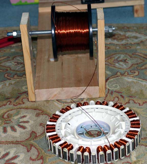
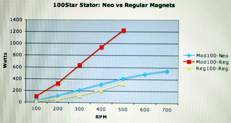
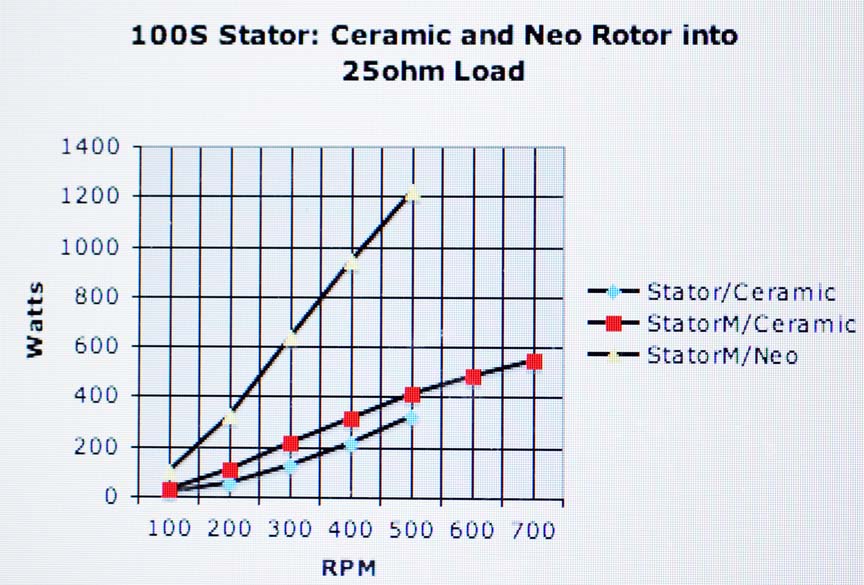
I rewound the 100s stator and compared it to the old version on my test bench. I also ran it and the neo rotor. Here is the graph comparing: old stator, ceramic rotor; new stator, ceramic rotor; new stator, neo rotor.
 |
| |
brucedownunder2
Guru

Joined: 14/09/2005
Location: AustraliaPosts: 1548 |
| Posted: 03:21am 31 Oct 2008 |
Copy link to clipboard |
Print this post |
|
Hi IM ,,, could you post a few pic's of those Neo's you get from China .. And the approx price ,,,I looked at your graphs ,, good stuff there.. I use the small Neo's ,but they are a bugger to fit,,224 of them ,,Please get back to us
Bruce
Bushboy |
| |
herbnz

Senior Member
Joined: 18/02/2007
Location: New ZealandPosts: 258 |
| Posted: 06:41am 31 Oct 2008 |
Copy link to clipboard |
Print this post |
|
Hi Imsmooth
Iam assuming the graphs are labeled wrong red is Neo;s ?
Is you 70 turns /coil all connected in series ? ie 3 lots of 14.
What load are you feeding ?
It is interesting that there is little difference at the start ie cutin only slighty earlier. This I long have suspected as the poles are saturated before any cuurent flows therefore you are only getting an increase in flux as if its an air core. but the dramatic increase is the stronger mmf allows more ampere turns before the rotor mmf is effectively neutralised. It is a little suprising that the reg magnets dont follow Neo's for a period then flattern out more
Herb |
| |
GWatPE
Senior Member
Joined: 01/09/2006
Location: AustraliaPosts: 2127 |
| Posted: 08:51am 31 Oct 2008 |
Copy link to clipboard |
Print this post |
|
I am a bit puzzled by the graph. Perhaps imsmooth can elaborate. Were the readings at 100,200,300, etc or at 50,150,250, etc
Gordon.
become more energy aware |
| |
oztules

Guru
Joined: 26/07/2007
Location: AustraliaPosts: 1686 |
| Posted: 10:25am 31 Oct 2008 |
Copy link to clipboard |
Print this post |
|
Herb,
I think it is more a case of how the figures have been presented. It would be difficult to imagine cutting in at 100w..... one assumes it was an arbitrary start point for the graph. I you extrapolate back, start up appears to be considerably lower than ceramics.
Saturation with the ceramics I feel is probably correct as you say, but the extra flux from the neo's is still extra flux in the coils, adding little to the steel, but still affecting the coils to give you your extra flux and so mmf... I would not expect the ceramics to follow the neo's for any time for this reason, and would hope startup is considerably earlier.... Motor conversions seem to benefit from more magnets and more magnets.... well into saturation and beyond.
It would be interesting to drive it further to see where the current limits, or if the neo's are strong enough to make the stator appear more like an air coil machine, and keep going to destruction......
.........oztules
Village idiot...or... just another hack out of his depth |
| |
imsmooth
Senior Member
Joined: 07/02/2008
Location: United StatesPosts: 214 |
| Posted: 02:27pm 31 Oct 2008 |
Copy link to clipboard |
Print this post |
|
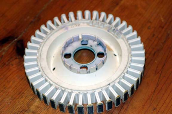
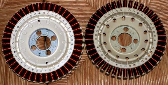
Yes. I mislabeled the graph. The one with the most power is the neo rotor. It was late at night when I put it together. Here is the corrected graph. I also have a picture of the modified stator and old stator.
There are pictures of the magnets at http://www.mindchallenger.com/wind
Is there something specific you want to see, Bruce? I forgot the exact price, but it was something close to $1.5 per magnet. I just emailed my manufactorer who will give me the pricing and shipping to Australia. If a few of you want them you will get a price break. One of you can receive them and distribute them to the rest, locally.
I want to update all of you that since I made the rotor there has been no warpage. It still spins smoothly. Of course, I have to see what happens when it is outside.
 |
| |
GWatPE
Senior Member
Joined: 01/09/2006
Location: AustraliaPosts: 2127 |
| Posted: 10:04pm 31 Oct 2008 |
Copy link to clipboard |
Print this post |
|
Hi imsmooth,
What gauge wire did you rewind with. The 100S notation is used exclusively to describe an original F&P stator wound with 1mm enamel wire with 14 coils in series. If you have wound with 1.2mm wire then this would be a rewind 120S or such.
The graph you presented obviously has the intersection at 50,0 and the readings were taken at 100rpm intervals and not what appears to be 50,150,250 etc.
Gordon.
PS Caps on a std 100S with ferrite rotor appear to do very well at 420rpm giving approx 600W. I wonder what caps would do for a neo rotor?
become more energy aware |
| |
imsmooth
Senior Member
Joined: 07/02/2008
Location: United StatesPosts: 214 |
| Posted: 11:42pm 31 Oct 2008 |
Copy link to clipboard |
Print this post |
|
I rewound with 18g, 1.0mm wire. The readings are at 100, 200, 300, 400, 500 and 600 rpm. The 25ohm load is very close to matching the impedance of the stator. I will have to retest the 80S stator to determine its impedance.
I also want to clarify that I picked the RPM values to measure voltage. Voltages were produced at much lower RPMs for all rotor types, but I didn't write them down.
Edited by imsmooth 2008-11-02 |
| |
GWatPE
Senior Member
Joined: 01/09/2006
Location: AustraliaPosts: 2127 |
| Posted: 06:23am 01 Nov 2008 |
Copy link to clipboard |
Print this post |
|
Hi imsmooth,
the loading graph with a single resistor I have to query.
I would expect the voltage to increase linearly with rpm. I would not expect a linear relationship of power to rpm with a fixed resistance output loading.
With my axiual flux mill, the output power goes up a factor of 4 for a doubling of the rpm into a fixed resistance, with 4 times the energy needed on the input drive.
The fact that you have a linear relationship indicates that the effective load impedance is increasing with increasing rpm, yet you say this was a test with a fixed resistance load that you had determined to be appropriate, [25ohms].
Have I missed something?
Gordon.
become more energy aware |
| |
imsmooth
Senior Member
Joined: 07/02/2008
Location: United StatesPosts: 214 |
| Posted: 01:36pm 01 Nov 2008 |
Copy link to clipboard |
Print this post |
|
I might have to redue it some time. Here are the open voltage values for the neo rotor and rpm's:
100rpm,67v; 200,130; 300,196; 400,267; 500,318; 600,378
I determined the rpm with a strobe. I was overdriving the motor and didn't want to leave the motor running too long. |
| |
oztules
Guru
Joined: 26/07/2007
Location: AustraliaPosts: 1686 |
| Posted: 08:14pm 01 Nov 2008 |
Copy link to clipboard |
Print this post |
|
Gordon,
I think it is the stator impedance that is changing with increased freq. (do the numbers)
.........oztules
Village idiot...or... just another hack out of his depth |
| |
GWatPE
Senior Member
Joined: 01/09/2006
Location: AustraliaPosts: 2127 |
| Posted: 10:47pm 01 Nov 2008 |
Copy link to clipboard |
Print this post |
|
Hi oztules,
I had done the numbers and I was hoping that there might have been a mistake in the presentation. I gather from the lack of discussion that this is what was expected. It appears like this a poor use of magnetic material in the F&P. The machine is basically a constant current source. This would be of limited use in a windmill, as we need to increase loading as the rpm increases, not decrease.
Gordon.
become more energy aware |
| |
imsmooth
Senior Member
Joined: 07/02/2008
Location: United StatesPosts: 214 |
| Posted: 02:05am 02 Nov 2008 |
Copy link to clipboard |
Print this post |
|
I will post the number I just ran for the 80S stator with the neos. Interestingly, a load of 37.5ohms was the impedance until I hit 500 rpm. As the rpm increased I had to increase the impedance to 67.5ohms to have a proper match. I had a friend run the variac while I strobed the rotor.
Edit: Here is the graph using an 80series stator with the neo rotor. I started with a matched impedance of 37.5ohms (blue). The power doubled until I hit higher RPMs. I noticed that the stator behaved as if the impedance was higher. I then got numbers using 67.5ohms (red), and although the power was less in the beginning, the higher end numbers showed a significant increase in power production. I will pursue this with the 100s rotor. The data points are at 100,200,300,400,500 and 600 rpm.
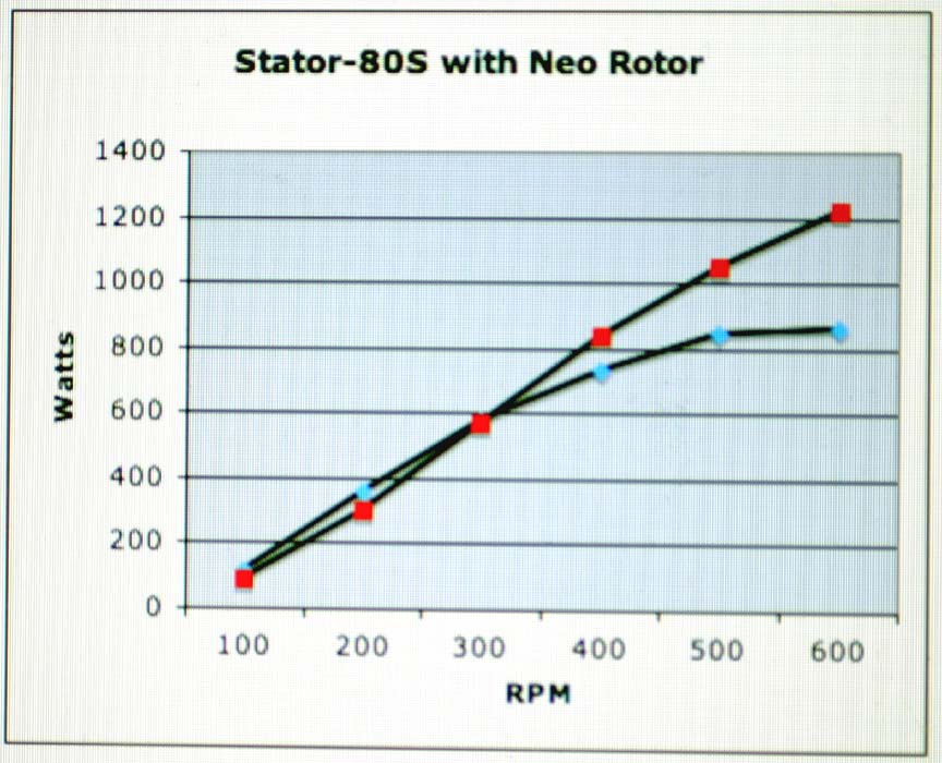 Edited by imsmooth 2008-11-03 Edited by imsmooth 2008-11-03 |
| |
Dinges
Senior Member
Joined: 04/01/2008
Location: AlbaniaPosts: 510 |
| Posted: 09:42pm 02 Nov 2008 |
Copy link to clipboard |
Print this post |
|
Imsmooth,
After rewinding, have you varnished/lacquered the coils? This is of utmost importance for a long servicelife. Otherwise the windings will chafe eachother and wear through the thin wire coating. A tiny speck of dust that finds its way in there (either during construction or during use) will speed up this wear even more.
The best you could do is a dry-bake-varnish job, using the proper (for your specific wirecoating) varnish. Most suited to perform that job would be a local motor rewinding shop, if there is one in your area. As an alternative, you could try impregnating the stator windings yourself using epoxy, and perhaps slightly heat the stator (40-50 deg.C) to heat up the epoxy (lower viscosity) and allow it to penetrate the nooks and crannies of the windings better.
If the above rewindings are just for testing purposes, fine. But if these rewind jobs will be put into service, I'd not skip the varnish job.
Peter. |
| |
imsmooth
Senior Member
Joined: 07/02/2008
Location: United StatesPosts: 214 |
| Posted: 11:59pm 02 Nov 2008 |
Copy link to clipboard |
Print this post |
|
I have already coated the stators with several coats of Shellac. This includes
the wire and iron cores. They are pretty water-tight. |
| |
