
|
|
Forum Index : Windmills : Testing Capacitors
| Author | Message | ||||
herbnz Senior Member Joined: 18/02/2007 Location: New ZealandPosts: 258 |
Hi dinges No problems with your simplified formula. Phill I personally would like to see testing into 24volt batteries in fact I would only take a casual interest in feeding a grid tie inverter as it is not a load I or a lot of others are using but if it is the type of load you use normally I understand if you use it. definitly resistive load is of no use. My testing here I drive the lathe from my inverter and feed back to my battery bank. Measuring the output as a DC value is also more direct as there is no side issues of power factor etc. I do not wish to confuse the issue all seem to accept leakage reactance as the reason caps work. I have in my testing a while ago used a stroboscope triggered from a referance pulse this shows what i think is the reason, you can see the rotor angle move so that the magnetic poles line up with the stator. This effect is the same that happens in large generators as power factor changes and excitation is changed . One of the tests I will try when I get my motor back is a short cct test to measure the reactance at full load current. In a separatly excited machine we use the field current to achieve this I figure in the FP I will disengage the rotor a little . Herb |
||||
| GWatPE Senior Member Joined: 01/09/2006 Location: AustraliaPosts: 2127 |
Hi Herb, Have you been able to confirm the power factor aspect, with output current and voltage phase relationships changing with series capacitance added? I am to test on the bench at low loads this aspect with an independent rectified system. I do not have an optically isolated DSO, and I have not been successful isolating inputs on the DSO I have, so current and voltage phase relationships have been difficult to see in the delta configuration. Monitoring the separated independent phases will hopefully make it obvious what is happening. Gordon. become more energy aware |
||||
| herbnz Senior Member Joined: 18/02/2007 Location: New ZealandPosts: 258 |
Hi I wish to do a lot testing with series caps I have tested and used parallel caps for years to determine optimin operating point for hydros I build. I have never looked at the leakage flux causing inductance in the stator, always thought caps worked by advancing the rotor flux as does leading pf in large machines. the standard tests for a generator are the open cct at full voltage and the short cct test at full current measuring input power. You test measuring the angle between I and V into a rectified load would give some indication if leakage is a factor. A scope with a common earth connection can be used as long as it and the cct is isolated from earth. Even a single channel by turning the time base into the other channel method used to create Lissajous's figures, the axis's of the eclipse are the cos of the angle if memory is correct.In your case of Delta there will be a phase shift of 30 degrees already of course. I will look at this when I get back my test motor. Another test might be to use true rms meters to measure AC values (moving iron meters safest bet not sure on these so called digital types ) work out VA then measure DC power other than the loss in the diodes dc should be true power. Herb |
||||
| GWatPE Senior Member Joined: 01/09/2006 Location: AustraliaPosts: 2127 |
Hi Herb, I am planning on testing the current and voltage phase relationships of an independently rectified phase. If the current and voltage are significantly out of phase and become in phase with capacitors, then power factor correction may be contributing to gains. Gordon. become more energy aware |
||||
fillm Guru Joined: 10/02/2007 Location: AustraliaPosts: 730 |
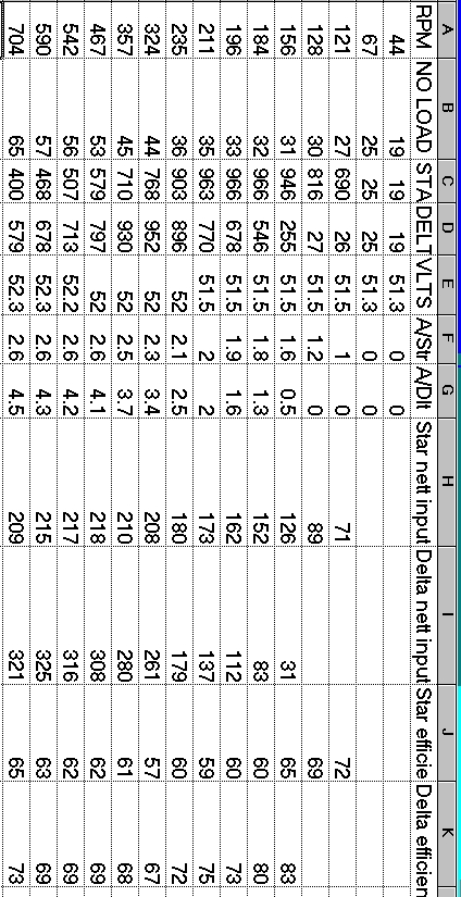
Hi All , I hope everyone has had a good christmas , I have done some initial testing to get a base on any improvements that can be made using caps/etc .. I have run through various speeds from 44rpm to 704rpm star and delta on a 80s unmodified and unclogged at 48V , the torque arm length is 846mm , I know most out there run 24V and 12V systems with modified stators but all mods to how the poles are rewired I think will react the same as watts stay the same , rewiring allows the blades not to stall at to low Rpms .. RPM--NO LOAD--STAR--DELTA--VLTS--A/Str--A/Dlt 44-- 19g -- 19g-- 19g--51.3-- 0 -- 0 67-- 25g -- 25g-- 25g--51.3-- 0 -- 0 121-- 27g --690g-- 26g--51.5-- 1 -- 0 128-- 30g --816g-- 27g--51.5-- 1.2-- 0 156-- 31g --946g-- 255g--51.5-- 1.6-- .5 184-- 32g --966g-- 546g--51.5-- 1.8--1.3 196-- 33g --966g-- 678g--51.5-- 1.9--1.6 211-- 35g --963g-- 770g--51.5-- 2.0--2.0 235-- 36g --903g-- 896g--52.0-- 2.1--2.5 324-- 44g --768g-- 952g--52.0-- 2.3--3.4 357-- 45g --710g-- 930g--52.0-- 2.5--3.7 467-- 53g --579g-- 797g--52.0-- 2.6--4.1 542-- 56g --507g-- 713g--52.2-- 2.6--4.2 590-- 57g --468g-- 678g--52.3-- 2.6--4.3 704-- 65g --400g-- 579g--52.3-- 2.6--4.5 Sorry the colums don't seem to line up when it is put onto the forum . It surprised me to how quickly the F&P becomes inefficient at producing power at high Rpms , one other test I did was to slowly turn the rotor buy using the drive pulley and lathe in low and watch the peak clogg weight 135g . Pic of torque arm and digital scales 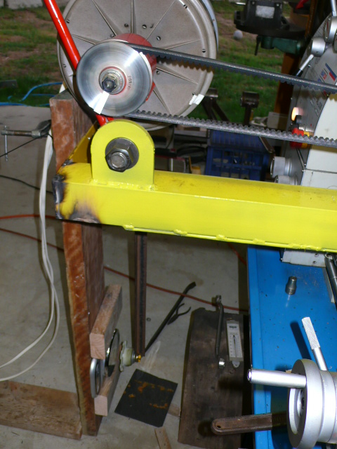
PhillM ...Oz Wind Engineering..Wind Turbine Kits 500W - 5000W ~ F&P Dual Kits ~ GOE222Blades- Voltage Control Parts ------- Tower kits |
||||
| KiwiJohn Guru Joined: 01/12/2005 Location: New ZealandPosts: 691 |
Deleted by me!  |
||||
Gill Senior Member Joined: 11/11/2006 Location: AustraliaPosts: 669 |
fillm, To retain the text formatting, use the CODE , /CODE enclosed in [ ] at the start and end of the data. You could edit your post now if you like so future readers will benefit. Great work !  was working fine... til the smoke got out. Cheers Gill _Cairns, FNQ |
||||
oztules Guru Joined: 26/07/2007 Location: AustraliaPosts: 1686 |
Do you happen to have the open circuit voltages as well for those RPMS? ..........oztules Village idiot...or... just another hack out of his depth |
||||
| Dinges Senior Member Joined: 04/01/2008 Location: AlbaniaPosts: 510 |
Phill, You've obviously spent a lot of time building your nice setup and then making accurate measurements. So I'm surprized you didn't make the next logical step by graphing the data and interpreting the results. I don't know about you, but the table with numerical values that you 'barfed out' in your last post is pretty useless to me. A shame, after all that effort you've put in. It left me dissatisfied enough to decide to graph the data myself for my own benefit. After I did so I figured I might just as well post it here for the rest of the forum. Based on your original data I calculated mechanical input power for both star and delta, electrical output power (using a constant voltage of 52V) for star and delta, and a smaller extra graph showing efficiency in both the star and delta configuration. See below. 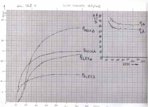
(high-resolution graph can be found here: http://picasaweb.google.com/motorconversion/Temp#52852022292 81633810) It's immediately obvious that efficiency in delta is much higher than in star, by about 10 percentage points. Not a little... Also, efficiency remains basically constant at the higher RPMs, as opposed to my induction conversions, where it seems to keep on falling as speed increases. Also the (what I assume to be) inductive-reactance limiting effect is very clear, as the curves flatten at increasing RPM. If we look at the situation in star for example, then both the mechanical shaft input power and electrical output power are constant above ~550RPM. In delta the real flat area seems to fall off the graph, it must be above 700RPM. Because of this inductive reactance limiting it's very important to make sure the windturbine furls in time, as otherwise it will overspeed. The graphed results should also be a big help in deciding (based on your local windsituation) whether to connect it in star or delta. Curious as to what the others have to say about the results. Peter. |
||||
| herbnz Senior Member Joined: 18/02/2007 Location: New ZealandPosts: 258 |
Hi Phil Excellent results I would for the record like to know the load ie is it a 48 volt battery ? Can you get some computer nut to set you up a spreadsheet to do the calculations ? I will in a few days if no one else does. Thanks Dinges for the graphs . The 80s has reached current limit when the dc current reaches about 2 amps this is in relation to the winding in delta of course it can go higher. Not really fair to say more efficent in delta its just more suitable for this load. in both cases we are over driving the unit we would need to reduce the turns. The caps will dramaticly change this current limit by what i think is supplying more excitation . Will spent more time on the results but at moment Grandkids to attend to Herb |
||||
SparWeb Senior Member Joined: 17/04/2008 Location: CanadaPosts: 196 |
Thank you! Great first run through. I don't mind raw data as much as Peter, but crunching your own numbers is satisfying, so you should try it. Since you have measurements for the input and output, Peter was able to quickly turn out a set of efficiency numbers, and I've been able to reproduce the same results on my computer. I went a step further and I've tried to equate the sum of the inputs to the sum of the outputs. The total input is greater than the total output (as I expected). The remainder is the "reactive power" I assume. Taking the Star tests at 357 RPM as an example, the lathe is putting 220 Watts of power into your generator. You are drawing out 130 Watts of electrical power charging the battery in DC. Also available is a number for losses in the bearings and hysteresis, which accounts for 14 Watts. The remaining 2 pieces are the resistance in the copper wiring, and the reactance loss. If you could give me a measurement of DC Ohms when the stator is wired in Star and in Delta, then I could complete the calculation. (I could guess, but better to just use the correct number before getting too far with it). I don't know if you've tried this, but the resistance measurement you get by clipping the leads of a multimeter across the line wires is not usually the same as the resistance you measure if you were to pass a DC current through the stator's line wires, and do an Ohm's law calculation. The difference is surprising on my motor conversions. Steven T. Fahey |
||||
| GWatPE Senior Member Joined: 01/09/2006 Location: AustraliaPosts: 2127 |
Hi sparweb, The resistance, as calculated with current flowing, has a reactive component, from current interactions with the iron[like a choke]. The resistance with a multimeter has a much lower current, so is closer to the wire resistance only. A series80 has a single coil wire resistance of approx 6ohms. Gordon. become more energy aware |
||||
| KiwiJohn Guru Joined: 01/12/2005 Location: New ZealandPosts: 691 |
So there we have it, my effort with Phill's numbers. I have calculated the nett input as the difference between the loaded and unloaded conditions which excludes things like bearing friction and windage. The efficiency is the ratio between this nett input and the DC output. As you can see these are not very high though you will note Peter D's earlier observation that delta is much higher. Where does all that lost energy go? |
||||
| Gizmo Admin Group Joined: 05/06/2004 Location: AustraliaPosts: 5012 |
Save the picture as a GIF file instead of a JPG file. The forum will save a GIF file at 1000 pixels wide instead of 500 pixels. The best time to plant a tree was twenty years ago, the second best time is right now. JAQ |
||||
| KiwiJohn Guru Joined: 01/12/2005 Location: New ZealandPosts: 691 |
Thanks Gizmo, I will remember for next time. |
||||
| GWatPE Senior Member Joined: 01/09/2006 Location: AustraliaPosts: 2127 |
Hi kiwijohn, The only component left that has the ability to affect the wasted power is the magnetic field interacting with the iron. The iron seems to create additional losses when current is produced, to that when there is no current. This may be leakage inductance at work. There appears to be about 40W of unexplained power lost, allowing for the rectifier and copper losses and unloaded iron losses at the 200W power level for delta configuration. Gordon. become more energy aware |
||||
| KiwiJohn Guru Joined: 01/12/2005 Location: New ZealandPosts: 691 |
Gordon, I suspect the power factor in the alternator is very poor and poor power factor means increased current which in turn means increased copper losses and increased magnetic fields and even further iron losses. |
||||
| GWatPE Senior Member Joined: 01/09/2006 Location: AustraliaPosts: 2127 |
Hi kiwijohn, I have done some testing of the "current" output waveform. 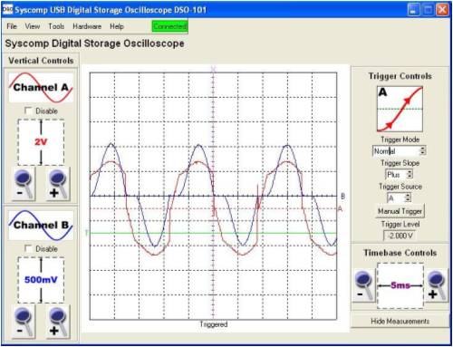
I had to insert a series resistor and measure the emf across it, in a single winding, to avoid complications from the other phases. There is a significant distortion to the current phase in relation to the voltage. The blue trace is the current. I have not seen any real changes to the waveforms yet in cap testing. Gordon. become more energy aware |
||||
| KiwiJohn Guru Joined: 01/12/2005 Location: New ZealandPosts: 691 |
Gordon, it looks like the voltage is pretty severly distorted by something? I think the current has a much better shape due to the smoothing effect of the stator inductance. However your readings are of great interest as the current and voltage does appear to be in phase so power factor is actually pretty good! Do you have capacitors in this circuit? If not, there goes the theory that capacitors bring improvement by improving the power factor. 
I suppose adding capacitors would help the voltage wave shape, using the simple theory that inductors smooth current and capacitors smooth voltage. |
||||
Bryan1 Guru Joined: 22/02/2006 Location: AustraliaPosts: 1206 |
Well guys I went and twisted the poles on my 100S finally and the today with the wind the genny sounded like a cricket on heat as the mag housing was scrapping on the stator. Even though it was windy I brought the genny down and re-aligned the stator so it wasn't touching. Now the genny starts with just a hint of wind so I did a quick trial with no caps. The best I saw was 3 amps without the caps. When I wind died down I put the caps back online and when the wind picked up I saw 8 amps in roughly the same wind. Anyway as I've had the caps on for ages I did a quick check of the uf with my fluke dmm and they are still showing the same 216uf the same as when they went on. 
The most surprising thing with the pole twisting unlike Gordons 100S which still makes that groaning noise the noise on mine has virtually disappeared. 
I'm expecting a gale here tonight and 1 huge gumtree across the road dropped a decent branch already. So later if I get a chance i'll go take a pic of the amp guage when the genny is going flatout. Cheers Bryan |
||||
