
|
|
Forum Index : Windmills : Testing Capacitors
| Author | Message | ||||
| GWatPE Senior Member Joined: 01/09/2006 Location: AustraliaPosts: 2127 |
For the benefit of readers, I have prepared a schematic. 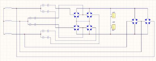
This should clear up the confusion. Gordon. become more energy aware |
||||
fillm Guru Joined: 10/02/2007 Location: AustraliaPosts: 730 |
Hi All , Thanks for the positive feed back , and 'yes, great idea' to Glenn about making a dedicated page to the use of caps , this would probabally be the best spot to put the graphs and raw data from the tests , one thing I would like to see is the bleed off resistors drawn into the wiring diag's and Res/value ,to be as safe as possible for all concerned , and the warning about dangerous stored voltage levels , and that they should be housed in an appropiate cabnet/box to keep inquisitive fingers away.. Glenn , mabe 48V systems could be included , I'm sure it was just a typo , as it matches up with the PVE 1200 grid inverter as more seem to want to connect wind/solar to the grid . John ,I can't wait to read your next scheme , "mabe a 5 Speed manual gear box and clutch pedal" .. Only joking !!  ,, Thanks for your comments and input.. ,, Thanks for your comments and input..
The only thing I have not , and probably don't need it with the twisted poles , is my bump start floating prop hub . I am still going to persivere with it as it enabled very low wind start up , and with the last recoil spring I fitted to the dual ,prior to the Quad, was when the drive pin hit the stator drive it would rotate the stators on spring tension and unload the blades , this will be even better with the twisted poles and I think the stators will be half a turn in front of the blades in light wind and be spring coupled uitill the load comes on , time will tell.. A question to all, I need to rebuild my annemometer and need a reliable reed switch , Any Ideas ? I have been using the F&P lid switch but are not likeing 48V .. PhillM ...Oz Wind Engineering..Wind Turbine Kits 500W - 5000W ~ F&P Dual Kits ~ GOE222Blades- Voltage Control Parts ------- Tower kits |
||||
| GWatPE Senior Member Joined: 01/09/2006 Location: AustraliaPosts: 2127 |
Hi herb, I believe that the output voltage unloaded should be proportional to rpm. The output power will be deteremined by the loading presented at a partricular rpm. The power output of a PermanentMagnetAlternator [PMA]follows a squared relationship only with a purely resistive loading. The capacitor doubler arrangements that I proposed and use on my windmill and Phill has continued testing and is now using on his windmill, alters the loading of the alternator to better match the wind energy curve. This arrangement is suited to a battery type loading[relatively constant output loaded voltage]. Resistive loading arrangements on a windmill may still benefit with AC coupling, with capacitors. Gordon. become more energy aware |
||||
| GWatPE Senior Member Joined: 01/09/2006 Location: AustraliaPosts: 2127 |
Hi Phill, I would add zeners, to around 12-24V total rating in series with one of the wires from the anemometer. This would limit the voltage to around a max 24V. The voltage would be increased until the pulses just stopped, and then the zener value reduced. I would use 6V2 zeners and just increase the number in series, until the cct still sensed. This arrangement will reduce the voltage on the reed switch contacts and will work better than just a resistor. Polarity will be important. The bar end of the zener should be towards the positive. Gordon. become more energy aware |
||||
| KiwiJohn Guru Joined: 01/12/2005 Location: New ZealandPosts: 691 |
Phill, you may be able to protect your reed switch by putting a diode in parallel that will squish any voltage spikes. |
||||
| GWatPE Senior Member Joined: 01/09/2006 Location: AustraliaPosts: 2127 |
Hi kiwijohn, In the arrangement that Phill has, 48V goes to the reed switch. The switched output only goes directly to a resistor/opto coupler diode/voltage limiting protection input cct. Unless the wiring is inductive, then the 5mA 48VDC is the problem. I know Phill tried a 5V supply, but insufficient level was output through the reed switch to activate the opto LED. Gordon. become more energy aware |
||||
oztules Guru Joined: 26/07/2007 Location: AustraliaPosts: 1686 |
Phil, Sounds like a hall effect ic out of a computer fan may be a better alternative.... probably better all round, and could do away with the opto coupler, and have a sharper switching edge. They really are easy to use. This link shows Dinges playing with them and turning into a believer (page 3). You can use your 5v without opto's and it just gets simpler and simpler.... .........oztules Village idiot...or... just another hack out of his depth |
||||
| Dinges Senior Member Joined: 04/01/2008 Location: AlbaniaPosts: 510 |
(removed for posting in the wrong thread.) |
||||
| GWatPE Senior Member Joined: 01/09/2006 Location: AustraliaPosts: 2127 |
PhillM has some more data from the new PVC blades on his dual ferrite rotor with star/doubler, delta doubler arrangements. The outputs closely follow the lathe test data. Will post some graphs when the analysis is completed. Gordon. become more energy aware |
||||
| dan_jenson Newbie Joined: 14/04/2010 Location: Posts: 1 |
LEESON has 1-phase in 1-phase out drives. I think it's called "FHP Series".http://www.clrwtr.com/LEESON-Speedmaster.htm |
||||
