Notice. New forum software under development. It's going to miss a few functions and look a bit ugly for a while, but I'm working on it full time now as the old forum was too unstable. Couple days, all good. If you notice any issues, please contact me.
Murphy's friend Guru Joined: 04/10/2019 Location: AustraliaPosts: 584
Posted: 08:19am 31 Dec 2021
Copy link to clipboard
Print this post
Don't worry about control (driver) boards, I have spares of all flavors here, including those Tony kindly sent me.
Do discuss the mosfet driver and power PCB's when you see me. There are two different approaches, one requiring 8 heatsinks of varying sizes and the other (my version) just two large heat sinks.
Alston Regular Member Joined: 04/04/2021 Location: AustraliaPosts: 63
Posted: 12:26pm 03 Jan 2022
Copy link to clipboard
Print this post
Thanks for the calculation Tony! I met with Klaus yesterday and had a look at his amazing Warpinverter and he gave me lots of tips on winding. He suggested going as up to 1.7mm for hand winding. That is 2.27mm2 so good for 9 amps. I could wind 3 layers for the primary which would get me to 27 amps, is that close enough since at 40v I would need 28amps (not that the battery will get down that far)?
I went through my box of transformers which are all in the 300VA range. I stripped one down today and it's core is OD=102mm,ID=60mm and a height of 40mm. Since I have multiple of these already I thought I could double stack the cores for transformer 3 which would give me 16.9cm2 core cross section area. So 107 primary turns and 67 secondary turns. I could get away with 1 layer of 1.7mm for the primary although that would give me just under the 9.3 amps I was aiming for.
Using 1 of these cores for transformer 4 I would need 643 primary turns and 134 secondary. The existing winding is 0.8mm wire so only good for about 2 amps, should I go up to 1mm since I would need 3.1amps at 40v? Fitting in 3 layers of 134 turns of 1.7mm won't work as I will run out of room. What if I double stack this core as well? Gets me down to 322 primary and 67 secondary which will give me more room to work with?
Warpspeed Guru Joined: 09/08/2007 Location: AustraliaPosts: 4406
Posted: 08:35pm 03 Jan 2022
Copy link to clipboard
Print this post
Transformer 2
Three layers of 1.7mm should be quite easy to handle, the thicker wire starts to becomes much stiffer and less user friendly. You are very fortunate to have Klaus there, he is expert at all this !
Spread the wire out around the toroid so each layer occupies the whole circumference leaving enough space between the ends for reliable insulation.
As there will not be any shortage of winding space on that core, three layers of 1.7mm for the secondary will be more than adequate (27 amp rating) and we only expect to see 21 amps tops.
Primary current will be the secondary current 21 amps x 75v/40v = 39.375 amps, so we need roughly 10mm sq there for that. So four or five layers of 1.7mm might be about right for the primary unless you have some different wire to use.
Transformer 3
That all looks spot on.
Transformer 4
Yes, the cores are not that large, and double stacking reduces the turns count by half which makes it a lot easier to wind. Its still a lot of turns to put on though !Cheers, �Tony.
Alston Regular Member Joined: 04/04/2021 Location: AustraliaPosts: 63
Posted: 10:54pm 03 Jan 2022
Copy link to clipboard
Print this post
I just realized I calculated transformer 4 wrong as I didn't change my output voltage when I calculated the flux density. So doing that again 105 primary and 22 secondary for a double stacked core or 211 primary and 44 secondary for a single core but I haven't had a look how much wire could fit through a single core yet. Those cores have 1.3mm windings for their secondaries so if I reuse that for the primary which I need 4.37amps so the 5 amps that will do will work well.
Warpspeed Guru Joined: 09/08/2007 Location: AustraliaPosts: 4406
Posted: 11:09pm 03 Jan 2022
Copy link to clipboard
Print this post
I didn't bother to check your figures for number 4.
We are still on number 2, and all the calcs for number thee look good too.
Its a really good idea starting with transformer two, as its always the easiest. The others for various reasons are slightly more tricky because of either size or larger number of turns.Cheers, �Tony.
Murphy's friend Guru Joined: 04/10/2019 Location: AustraliaPosts: 584
Posted: 10:09am 04 Jan 2022
Copy link to clipboard
Print this post
Paul, its that 60mm ID that will be your problem. Remember, its not just the wire, its also the winding method (spool, shuttle, hoop) that has to pass through that hole freely as you wind. I have seen toroidal home wound jobs posted here where the last turn of the primary completely filled the hole. This is cutting it a bit fine IMO and won't be fun with the many turns of primary required for the tiny transformer.
The smallest core in my warpverter had a 80mm hole and was easy to wind. The others were 90+ mm, the largest had a 100mm hole.
If, as you mention, you have several of those 60mm ID transformers see if the core laminate can be unwound from the inside and placed back on the outside to make the hole bigger. This, of course, reduces the area so you will have to wind on outside more laminate than you removed inside or stack cores. Go for 80mm ID minimum for the tiny core and throw your theoretical available winding space table out the window . It all boils down what can be done easily by hand winding.
Murphy's friend Guru Joined: 04/10/2019 Location: AustraliaPosts: 584
Posted: 05:15am 05 Jan 2022
Copy link to clipboard
Print this post
Further to my reply above, I have just measured the remaining hole of a fully wound 3KW Aerosharp core. It was 50mm. Considering the blank core had a 100mm hole we can see they used only 75% of the available hole area, the rest being required for the winding machine hoop. Now, these factory toroidal transformers do not waste any space so we can take that as a good rule of thumb for hand winding too.
So, for your calculations, your available area for windings is 75% of the blank core hole area. If you are careful with insulation layers that should do the trick. Do not forget to include space required for primary/secondary insulation. If you wind your 3 in hand secondary carefully there is no need for insulation between the 3 layers if the wire enamel is in good condition as there is little or no voltage difference between layers at each point around the circumference.
Here is a list of the core holes I used:
Large core had 100mm diameter for a double stack core, you need perhaps 110 mm or more for a single stack (more turns required). Medium core had 96mm diameter. Small core had 95mm diameter. Tiny core had 80mm diameter.
I used 3 x 1.7mm dia. wire for the secondaries.
Warpspeed Guru Joined: 09/08/2007 Location: AustraliaPosts: 4406
Posted: 10:31pm 05 Jan 2022
Copy link to clipboard
Print this post
All excellent advice.
The transformer manufacturers always use minimum steel and copper to keep costs down, so their toroids are always completely full.
We are recycling old, often free stuff, and using a larger core than strictly necessary with a larger hole sure makes winding a lot easier.Cheers, �Tony.
Warpspeed Guru Joined: 09/08/2007 Location: AustraliaPosts: 4406
Posted: 04:18am 06 Jan 2022
Copy link to clipboard
Print this post
Paul, parts have been posted. From my experience sending things to Klaus, might take about a week.Cheers, �Tony.
Alston Regular Member Joined: 04/04/2021 Location: AustraliaPosts: 63
Posted: 01:24am 07 Jan 2022
Copy link to clipboard
Print this post
Thanks Tony!
Thanks for the advice Klaus, makes perfect sense and I am sure having a much larger ID than I need will help greatly. I will need to have a look around for a new TX 3 but I am going to see if I can get away with double stacked core for TX 4. They don't look like I can get them apart that easily.
Klaus you mentioned the Boat Coat epoxy you used, how does that differ from normal fibreglass resin?
Murphy's friend Guru Joined: 04/10/2019 Location: AustraliaPosts: 584
Posted: 09:39am 07 Jan 2022
Copy link to clipboard
Print this post
'normal' fibreglass resin is polyester or vinylester? based it does NOT make a suitable glue. Its only good to bond glass fibre.
Epoxy resin makes an excellent glue, there are many different brands and mixing ratios of that stuff. 2:1 ratio is easiest IMO for locking the winding turns in the toroidal core hole.
Godoh Guru Joined: 26/09/2020 Location: AustraliaPosts: 379
Posted: 09:14pm 07 Jan 2022
Copy link to clipboard
Print this post
In the way back when, I was a motor rewinder we used to dip our windings in a varnish tank and bake them. The varnish went very hard and bound the wires together well. Of course a motor winding is in slots as well so dipping and waiting until the bubbles stop was a good way to get good varnish penetration. When a job was urgent we would, first connect the windings to a lower voltage than they were designed for, and allow them to heat up. Then we would pour two part epoxy over the winding from one end, then turn the stator over and repeat. The epoxy went off very fast as the core and windings were hot, and also the heat allowed the epoxy to penetrate well. Warming the torroid core up and pouring epoxy would work well, although getting hold of some varnish from a motor rewind shop would probably be better. Just dipping the whole core in a varnish tank and either baking it or allowing it to air dry would probably give best penetration. The powerjack transformers that I have altered were not varnished or epoxied at all. But then we would not be buying new inverters off manufacturers if they made them too well would we. Pete
Murphy's friend Guru Joined: 04/10/2019 Location: AustraliaPosts: 584
Posted: 09:41am 08 Jan 2022
Copy link to clipboard
Print this post
Pete, way back when I was an apprentice I would have to do what you described above.
Heating and 'baking' a semi wound toroidal transformer at each layer is not really practical, especially if the oven in the kitchen has to be commandeered for this .
What I suggested to Paul is to, after ONE layer of the winding was added, jam out (against the hole wall) the turns *inside* the hole with a waxed, split, PVC tube section. Then pour a little epoxy resin just around the PVC tube to securely lock the pushed out wires in place. The next layer is added after the epoxy has set and the PVC tube has been removed. Each added layer is epoxy locked inside the hole only.
I saw no need to epoxy (or varnish) the *entire* transformer when the final winding was completed. Instead the outside was tightly wound with herringbone tape and that was also epoxy coated.
With all inside layers and the final outside layer bound solid in epoxy that transformer (and all the others I wound) is very quiet. The slight hum my inverters emit comes from the choke. These could benefit from epoxy 'baking' but I did not bother. The hum volume tells me how hard my inverter is working but its low enough to be also ignored.
Godoh Guru Joined: 26/09/2020 Location: AustraliaPosts: 379
Posted: 09:01pm 08 Jan 2022
Copy link to clipboard
Print this post
Sounds like a good way to go Mr Murphy. I have a couple of inverters that run 8010 boards, one of them I wound a new primary on as the voltages were not right, powerjack must have been doing something strange, so instead of taking 4 turns off the primary I took it off. I had some 6mm solar panel cable so used 6 in parallel for my primary ( 24 volt system), It is very quiet and runs well, I can run my air compressor and MIG welder no problems and hardly any noise, until the fan comes on that is. I have thermostats that turn the fan on at 40 degrees just to be on the safe side. Our ambient temp where I live rarely gets to 30 C, On high voltage motors we used to still dip the windings, even with up to 12 layers of mica and glass tape. I guess the varnish was there to seal the glass tape and stop vibrations in the slots. None would have got through to the actual windings anyway. pete
Alston Regular Member Joined: 04/04/2021 Location: AustraliaPosts: 63
Posted: 12:20pm 28 Feb 2022
Copy link to clipboard
Print this post
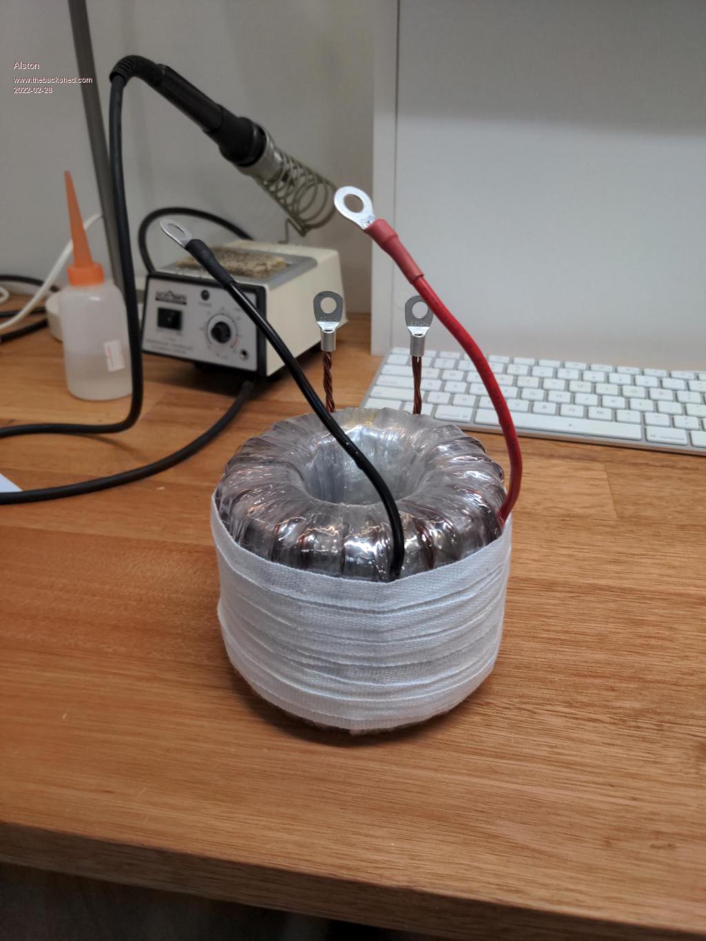
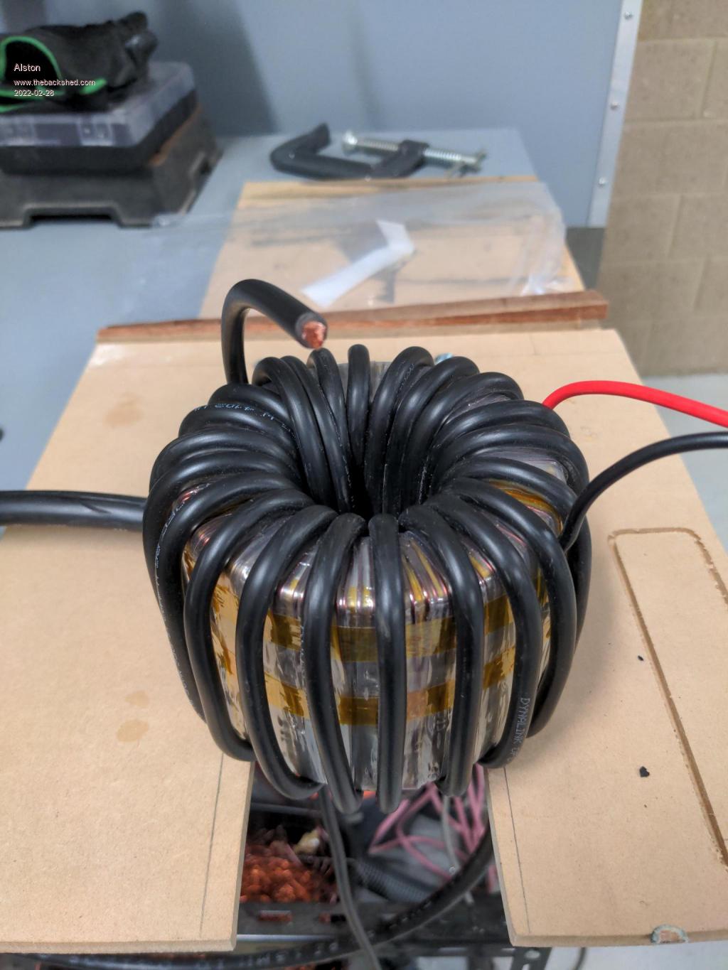
Well after having a paid project come up I am back to winding transformers. I have finished transformer 4 aside from coating the fabric tape on the outside with epoxy. To start with I printed out templates for my primary windings and stuck those on the ends which made life much easier. Although Klaus warned me about the difficulties with using standard high current cable for the secondary I still had to try it myself to see how calculations and the real world don't line up. I was able to use all of the 1.3mm wire that I unwound and twisted it like Klaus to make my secondary which worked nicely.
Alston Regular Member Joined: 04/04/2021 Location: AustraliaPosts: 63
Posted: 09:06am 26 Mar 2022
Copy link to clipboard
Print this post
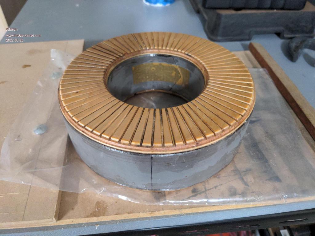
After looking at Roger's recent post with his incredibly wound transformers I was given an idea to use my CNC machine to cut the template onto the plywood endcaps. I have made the end cap for transformer number 2 which I will now start winding. I really need to find out where Klaus got his better quality plywood from as the stuff Bunnings has is junk, it doesn't machine very cleanly.
Godoh Guru Joined: 26/09/2020 Location: AustraliaPosts: 379
Posted: 09:09pm 26 Mar 2022
Copy link to clipboard
Print this post
Hi Alston, looks great. Plywood comes in better quality at a price. Marine grade ply would probably be better, but it is more expensive. Other than that using some fibreglass sheet ( used in large electric motor winding and former manufacture) would be even better. I don't know how hot your transformer core would get, I have thermostats in my inverters that turn on the fan if the transformer outer gets above 40 degrees C. How hot the core gets is another matter. Good luck. As far as insulated cable for the primary goes, I would mine with what I had which was some left over 6mm Solar Panel cable. I used 6 cables in parallel for my 24 volt 8010 based inverter and it is working great. Pete
rogerdw Guru Joined: 22/10/2019 Location: AustraliaPosts: 803
Posted: 02:00pm 27 Mar 2022
Copy link to clipboard
Print this post
Agreed, that looks awesome. Having the slots cut all the way across is perfect and I'm sure is even better than just grooving the edges like I did ... should keep the wire perfectly alighned.
I always worried about on what face to angle across to the next slot ... but I don't think it really matters whether it is on one of the ends or on the inside or outside.
Having the first layer well laid out makes such a difference to the following layers and I feel that really is the secret to a neat transformer.
I had wondered about 3D printing the end caps, but was worried about the print melting and perhaps decomposing to some degree. I've seen some horrible gooey messes when various materials start to break down with heat, age and chemicals ... so I dropped that idea altogether.
My plywood came from Bunnings too, but because I only filed little grooves into the corners/edges, it wasn't much of a worry. I did end up painting them with the epoxy resin that I used to glue it all together with, so it has some protection ... and ended up nicely sealed and smooth.
I assume you are planning on fitting some insulation around the core and inside it too?
Alston, in one of your photos above I can see some (I assume) IGBT's ... what type are they and what sort of specs? Also, what voltage and power are you aiming for with your inverter?
Fibreglass sheet does sound good Pete ... if I ever do more in the future I might look into that.Cheers, Roger
Alston Regular Member Joined: 04/04/2021 Location: AustraliaPosts: 63
Posted: 12:19pm 28 Mar 2022
Copy link to clipboard
Print this post
Well I have put the first layer of windings on and the slots definitely help alot. I still don't seem to be able to get it as perfect as yours Roger! I also coated mine in epoxy as per Klaus's instructions. I have fitted insulation on the inside and outside of the core, the photo above was take just after the epoxy dried.
I am building a 48v 5kw inverter. The IGBTs are Eupec/Infineon ones rated at 400 amps, I got them because they were cheap from a surplus place on eBay.
rogerdw Guru Joined: 22/10/2019 Location: AustraliaPosts: 803
Posted: 01:45pm 28 Mar 2022
Copy link to clipboard
Print this post
That's good, I was wondering what type you might use, or whether you might just use epoxy.
Thanks for that. I still haven't worked out what I'm going to use for my big inverter ... but expect I'll just use mosfets for the smaller three.
I recall in other threads where Warpspeed suggested IGBT's ... and he was keen on them especially for the higher voltage supplies (his was 90+ volts) ... but then I wasn't sure if he was suggesting they weren't so good for lower voltage supplies or not.
I certainly miss having him around to clarify some of these finer points ... where are you Tony, please come back! Cheers, Roger


 . It all boils down what can be done easily by hand winding.