
|
|
Forum Index : Microcontroller and PC projects : Help please - Picomite with SPI LCD
| Page 1 of 2 |
|||||
| Author | Message | ||||
| Glen0 Regular Member Joined: 12/10/2014 Location: New ZealandPosts: 77 |
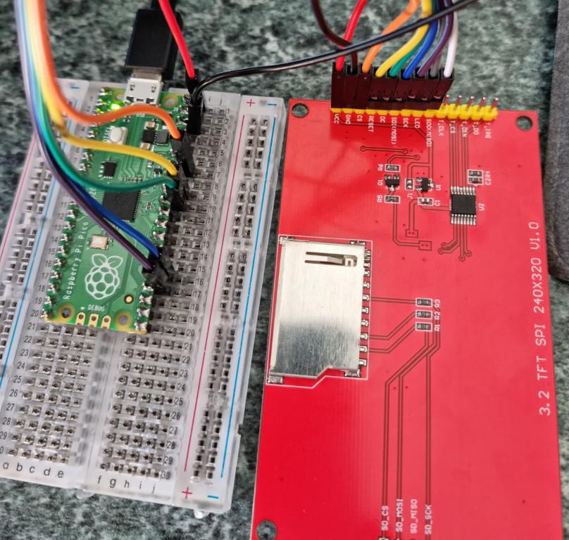 I have just received some LCD screens through Aliexpress and I cannot get them to work. The screen lights up when the Pico is powererd up and there is a very brief scrambling of black lines and then it reverts to a white screen. I have tried connecting as per the Picomite manual as well as the Silicon chip article but no go. I am trying to get it working as a display only first and once that is working I will try my hand at touch and SD. That brings me to another point, the website says this LCD is "no touch" yet it looks suspiciously like it has that option. Can anyone confirm this from the pictures which I hope have uploaded successfuly? This is the description of the display on the website, "SPI module 14 pin 3.2 inch 18P ILI9341 TFT LCD colorful screen 4 wire Serial port 320x240 No touch panel adapter PCB board"  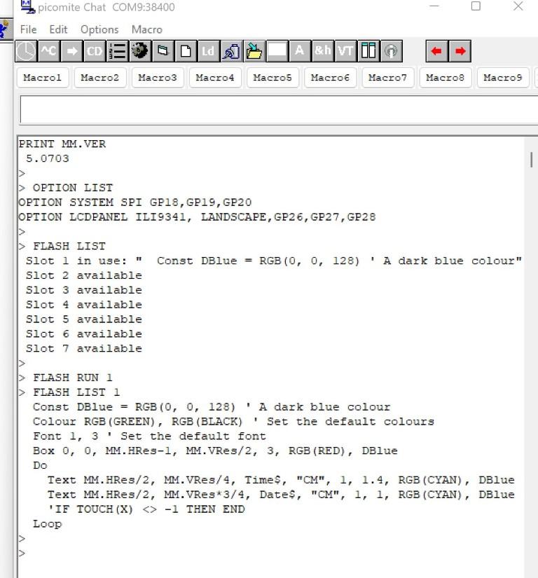 Edited 2022-01-28 07:15 by Glen0 |
||||
| phil99 Guru Joined: 11/02/2018 Location: AustraliaPosts: 1772 |
The board appears to have the touch chip fitted, but to see if the touch foil is also fitted look at the top side, connector end there will be a four way flexible PCB strip running from the top of the panel and down under it. |
||||
| lizby Guru Joined: 17/05/2016 Location: United StatesPosts: 3008 |
Don't know that it would make a difference, but MISO appears not to be connected. Also, although the Picomite manual shows GP20 as a MISO pin, the PICO pinout image that I have followed doesn't. PicoMite, Armmite F4, SensorKits, MMBasic Hardware, Games, etc. on fruitoftheshed |
||||
| hitsware2 Guru Joined: 03/08/2019 Location: United StatesPosts: 705 |
As I understand , MISO is not used with displays .... It would be transmit from the display ( doesn't happen ) my site |
||||
disco4now Guru Joined: 18/12/2014 Location: AustraliaPosts: 843 |
When powering from 3.3v you should bridge J1 which bypasses the regulator. Normally seems to work without doing this, but should be done to ensure you are getting 3.3v It seems to have the touch chip, if on the screen side you can see a separate 4 wire ribbon going to the top layer of the screen then it likely to have touch. You can use the PIXEL command and function to see if the screen is talking to you even if it has not initialised properly. PIXEL 0,0,RGB(RED) to set a pixel at 0,0. then ? HEX$(pixel(0,0)) to read it. Returns FC0000 for red if it works. (You need MISO connected to read the pixel. Is your white wire going somewhere we can see?) Edited 2022-01-28 08:01 by disco4now Latest F4 Latest H7 |
||||
palcal Guru Joined: 12/10/2011 Location: AustraliaPosts: 1796 |
In the TEXT line you have "CM" I think it should just be CM no inverted commas. "It is better to be ignorant and ask a stupid question than to be plain Stupid and not ask at all" |
||||
| lizby Guru Joined: 17/05/2016 Location: United StatesPosts: 3008 |
As I understand, MISO is used for BLIT READ (but isn't needed if you only write to the display--thus "Don't know that it would make a difference"). PicoMite, Armmite F4, SensorKits, MMBasic Hardware, Games, etc. on fruitoftheshed |
||||
| palcal Guru Joined: 12/10/2011 Location: AustraliaPosts: 1796 |
I have never used the "" with the alignment but apparently it works either way. Edited 2022-01-28 08:53 by palcal "It is better to be ignorant and ask a stupid question than to be plain Stupid and not ask at all" |
||||
| Glen0 Regular Member Joined: 12/10/2014 Location: New ZealandPosts: 77 |
Thanks for all the help. I hope the following responds to all the contributions: I checked the front of the screen and it does have the the Touch 4-conductor ribbon to the top. I am powering from VBUS, so it's 5V. I also tried using an externally powered USB hub. MISO not connected. (as per Silicon Chip mag) Tried the Pixel command and it returned FFFFFF Removed the inverted commas from both CM's and no change Is there maybe something I am doing wrong with MM Edit Do I need to have the Touch terminals connected? |
||||
TassyJim Guru Joined: 07/08/2011 Location: AustraliaPosts: 5880 |
It's nothing to do with MMEdit Try GUI TEST LCDPANEL That tests the display without having to worry about programming issues. Jim VK7JH MMedit MMBasic Help |
||||
| disco4now Guru Joined: 18/12/2014 Location: AustraliaPosts: 843 |
You don't need touch connected, but if you do connect T-DO, T-DI, T-CLK you must ensure T_CS is high to ensure the touch does not interfere with the SPI. OPTION TOUCH will pull T_CS high. Leave them unconnected until you get screen going. Have you tried GUI TEST LCDPANEL at command line. This will send a stream of circles of different colours to the screen. The PIXEL read will only work with MISO connected. Could be worth trying, if it reads successfully you have proved SPI is OK and the issue is initialising the LCDPANEL. Latest F4 Latest H7 |
||||
| hitsware2 Guru Joined: 03/08/2019 Location: United StatesPosts: 705 |
I see now that some displays ( maybe most ?) ( but not the one I have ) have a MISO pin . my site |
||||
| disco4now Guru Joined: 18/12/2014 Location: AustraliaPosts: 843 |
Try these new POKE commands to see if they do anything. Again will prove the SPI if they turn screen on/off POKE DISPLAY &H28 POKE DISPLAY &H29 Also these in case the colours are inverted, e.g. black is white POKE DISPLAY &H20 POKE DISPLAY %H21 Latest F4 Latest H7 |
||||
| Glen0 Regular Member Joined: 12/10/2014 Location: New ZealandPosts: 77 |
Thanks I tried all the actions recommended but no luck. I later noticed a solder jumper on the board "J1" and bridged it out with a little solder and now for a very brief time when powering on it displays the date and time as per the program but then it goes blank again. Progress I suppose. Any ideas? |
||||
| Glen0 Regular Member Joined: 12/10/2014 Location: New ZealandPosts: 77 |
The jumper brides out 2 of 3 pins on a small smd component, "U1", which is a "662K" If I am correct this is a voltage regulator and it bridges the in and out pins. Edited 2022-02-02 13:49 by Glen0 |
||||
| phil99 Guru Joined: 11/02/2018 Location: AustraliaPosts: 1772 |
"If I am correct this is a voltage regulator and it bridges the in and out pins." Yes it does, if powering from 5V that will damage any 3.3V item attached such as SD card and PicoMite. Only bridge J1 if using 3.3V. Most use 5V with J1 open. |
||||
Bill.b Senior Member Joined: 25/06/2011 Location: AustraliaPosts: 225 |
Have set up the LCD panel at the command prompt. From the manual Page 48 :- "To match the above connections the following configuration commands should be entered, one by one at the command prompt: OPTION SYSTEM SPI GP18, GP19, GP16 OPTION SDCARD GP22 OPTION LCDPANEL ILI9341, L, GP15, GP14, GP13 OPTION TOUCH GP12, GP11" Bill In the interests of the environment, this post has been constructed entirely from recycled electrons. |
||||
| Glen0 Regular Member Joined: 12/10/2014 Location: New ZealandPosts: 77 |
I think the Pico has survived despite the 5V, luckily. Does the fact that soldering the jumper gives a brief correct display at power-up, help in pointing out where the problem is? I have been following the manual to the letter, hopefully and all options entered accordingly. Thanks |
||||
| phil99 Guru Joined: 11/02/2018 Location: AustraliaPosts: 1772 |
To see if that regulator is working measure the voltage on both pads of J1. There should be 5V on one and 3.3V on the other. The metal case of the SD socket is a good ground point. Running out of ideas. |
||||
| Mixtel90 Guru Joined: 05/10/2019 Location: United KingdomPosts: 5705 |
Is the backlight lit? Try a 100R resistor from the LED pin to 3V3. Failing that, try it to GND instead. I don't think I have a circuit for the 3.2" display. Some of the displays use a simple resistor to set the brightness but Q1 isn't fitted. Where Q1 is fitted the backlight is powered via that and you can connect the LED pin to a PWM output to dim the display. Edited 2022-02-02 17:49 by Mixtel90 Mick Zilog Inside! nascom.info for Nascom & Gemini Preliminary MMBasic docs & my PCB designs |
||||
| Page 1 of 2 |
|||||
