
|
|
Forum Index : Microcontroller and PC projects : PICOMITE oscilloscope
| Author | Message | ||||
| Mixtel90 Guru Joined: 05/10/2019 Location: United KingdomPosts: 5726 |
Fair enough - I just wouldn't attempt to emulate a CRT. :) IMHO the parallel DAC will read fast but only at 6-bit resolution unless you can find a *much* better one with a parallel interface (I'd guess at 12 bits minimum if you want to display anything meaningful). With a low resolution DAC you're probably going to have to interpolate values to get something like a display. Your processing time has been reduced on reading and increased a lot on processing. I'm not saying it can't be done, but you'll end up writing in C or C++ I think if you're going to get something like. Possibly even using one CPU for capture and the other DMAing for display. It's not a MMBasic project if you want real speed. Possibly not even a RP2040 one. It's quicker and easier to buy an analogue scope. :) Mick Zilog Inside! nascom.info for Nascom & Gemini Preliminary MMBasic docs & my PCB designs |
||||
| hitsware2 Guru Joined: 03/08/2019 Location: United StatesPosts: 705 |
I think I can live without " real speed " Maybe an epaper display to get some persistence (like a CRT) my site |
||||
| Mixtel90 Guru Joined: 05/10/2019 Location: United KingdomPosts: 5726 |
I'm sure that getting a trigger pulse (or an auto trigger) then doing one screen width of captures as fast as possible then doing the display is the direction to go in. You'll get a nice, flicker-free display that updates at a controlled rate. Especially if you alternate two screen pages, clearing one and writing to the other alternately, toggling them at the beginning of each display scan. It's not something I've tried though. :) Mick Zilog Inside! nascom.info for Nascom & Gemini Preliminary MMBasic docs & my PCB designs |
||||
| phil99 Guru Joined: 11/02/2018 Location: AustraliaPosts: 1781 |
Some time ago I looked at building an analogue front end for the MM+ one and soon concluded it was too much effort for an audio scope. Wound up getting a JYE-Tech kit from BangGood. Better and cheaper than I could have done. |
||||
| JohnS Guru Joined: 18/11/2011 Location: United KingdomPosts: 3659 |
Which did you get? John |
||||
| Mixtel90 Guru Joined: 05/10/2019 Location: United KingdomPosts: 5726 |
I have one of these from JYE. It's amazing how many functions and controls you can fit on a button. :) It's actually quite usable. Mine's an older one in a white case. I think it was about 45 UKP when I got it. It doesn't get used a lot since I got a much better one, but at least it fits in a pocket and is fully isolated from all supplies - no mean feat for a scope. Mick Zilog Inside! nascom.info for Nascom & Gemini Preliminary MMBasic docs & my PCB designs |
||||
| twofingers Guru Joined: 02/06/2014 Location: GermanyPosts: 1133 |
I bought a FNIRSI-1C15 (500MS/s) for 54 EUR (incl. shipping from Aliexpress EU) and I am also very satisfied. It's amazing what you get for the money these days. Of course, this is not comparable to a MMBasic DSO. Still, IMHO it's an interesting project and good practice. Regards Michael |
||||
| Mixtel90 Guru Joined: 05/10/2019 Location: United KingdomPosts: 5726 |
That looks a nice little scope. My little JRE is good, but clumsy to use, only having a single button for everything! TBH it's rarely that I want to look at anything much out of the audio band now. You can usually slow logic down nowadays if you need to (unless you are specifically looking for glitches) and I'm not doing much with radio now. I did want a dual trace DSO though - I've wanted a "proper" scope for many, many years. It's only a Hantek DSO5102P (expensive by my standards), but it's been an eye opener for me, being able to zoom and pan over the traces and save them to a USB stick! Useful when I'm digging round inside an old Nascom. :) Edited 2022-01-31 02:11 by Mixtel90 Mick Zilog Inside! nascom.info for Nascom & Gemini Preliminary MMBasic docs & my PCB designs |
||||
| KD5ZXG Regular Member Joined: 21/01/2022 Location: United StatesPosts: 53 |
Even with a bunch of op-amps, these circuits seem crude. Most probes will assume 1Meg input impedance, not 2K or 10K. Also completely ignoring the need to compensate such that AC divides by capacitors at same factor DC divides by resistors. This is what keeps square waves looking square. 50 could work for an active probe, but those don't come cheap. If both ends match the coax, no need for further compensation. I've got the Digilent Analog Discovery. I think they post full schematics and theory. You might look those drawings over. The USB bus may want power and data isolation. I just tested a new part that may or not exist yet. I'll link when it does. Or perhaps isolate an ADC and probe front end from the Pico? https://www.ti.com/lit/ds/symlink/amc1336-q1.pdf Figure 54 on Page 29. If you can disconnect and float the whole scope on a battery even better. Why make more complicated than it has to be... Edited 2022-01-31 04:54 by KD5ZXG |
||||
| phil99 Guru Joined: 11/02/2018 Location: AustraliaPosts: 1781 |
"If you can disconnect and float the whole scope on a battery even better. Why make more complicated than it has to be.." Indeed, many cheap appliances have the control circuit floating at mains voltage, making servicing difficult with a earthed scope. These little scopes use little power and easily run from a AA pack. The one I have is:- JYE DSO Shell (DSO150) Oscilloscope DIY Kit |
||||
| twofingers Guru Joined: 02/06/2014 Location: GermanyPosts: 1133 |
I also have a DSO150 and don't think it's that bad. I think I paid less than 30 EUR - actually I only miss the battery (+ voltage converter and charging circuit), which I wanted to have designed for a long time ... |
||||
| twofingers Guru Joined: 02/06/2014 Location: GermanyPosts: 1133 |
double post, sry Edited 2022-01-31 08:24 by twofingers |
||||
| ztoti Regular Member Joined: 27/10/2011 Location: CanadaPosts: 65 |
I now that small scope on aliexpress is available for low price, but I'm happy with audio range scope. I'm not trying to replace the real scope, the PICO scope is just one part of my project. I'm building breadboard lab which include: 1. 3 channel full controlled power supply ( +-voltage control, current control, timer mode, graphic mode) 2. Function generator 3 Voltmeter, amp meter, RLC meter, ESR meter 4. small oscilloscope 5. frequency counter 6. Curve tester 7. maybe logic analyzer Check out the screens from my power supply ( everything works great) and when I finish the project I'll upload the schematic and .bas file 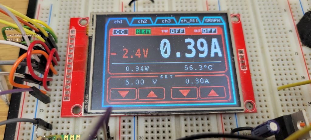 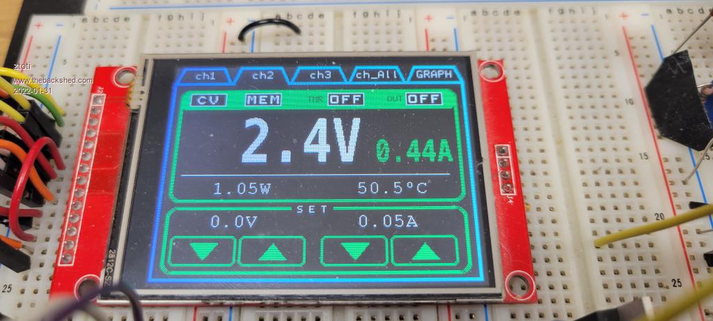 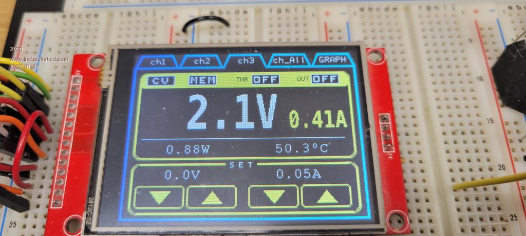 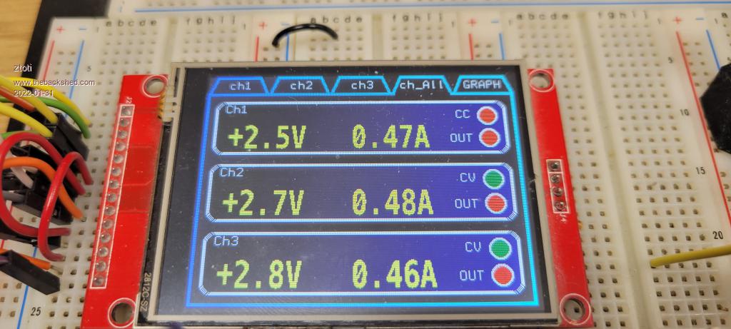 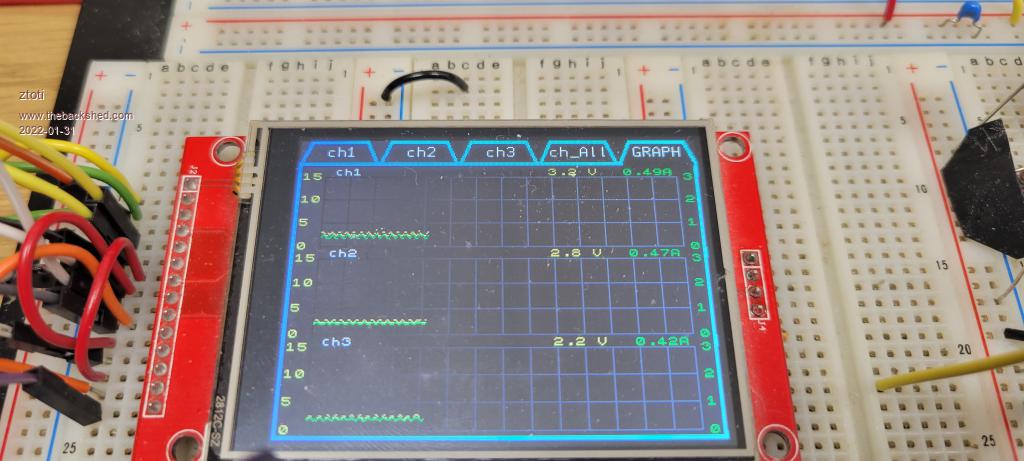 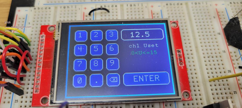 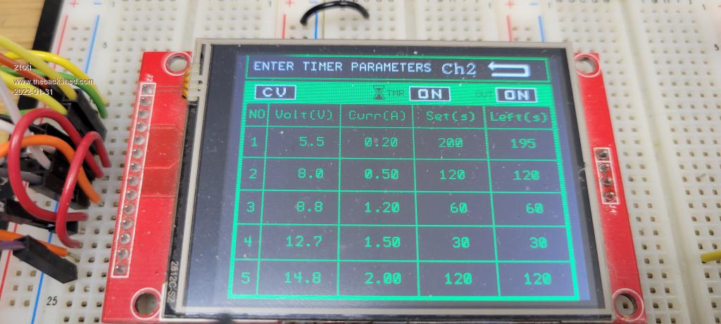 |
||||
| hitsware2 Guru Joined: 03/08/2019 Location: United StatesPosts: 705 |
Here's Mine ...... :) 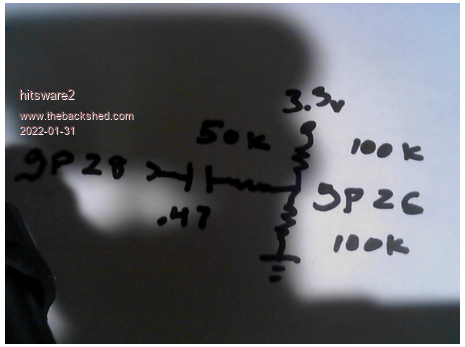 SetPin gp28, pwm6a ' bonus 5 kHz generator PWM 6,5000,50 Dim v!(127) ADC open 500000,1 Do CLS ADC start v!() For x%=0 To 127 Pixel x%,20*v!(x%) Next x% Pause 200 Loop my site |
||||
| Volhout Guru Joined: 05/03/2018 Location: NetherlandsPosts: 3527 |
@ztoti, That is a nice project. How do you control the individual power supplies ? I2C ? Is it your intention to run all the lab instruments on one micromite, or does each instrument have it's own micromite ? Interesting project, @hitsware, That is the circuit I use to measure the mains voltage (with a resistor in series with the capacitor). The mains voltage is isolated by a transformer (8Vac) to keep me from being electrocuted... Volhout Edited 2022-01-31 17:23 by Volhout PicomiteVGA PETSCII ROBOTS |
||||
| Mixtel90 Guru Joined: 05/10/2019 Location: United KingdomPosts: 5726 |
It's handy to put a high value resistor across the cap, Volhout, just so that you don't get a 2xpeak spike into your system next time you connect the mains input. :) I saw an application note for a PIC microcontroller where, to detect zero crossing, they simply connected an input pin to Live via 1M and used a capacitive dropper to power the PIC. Apparently the protection diodes on the PIC are sufficiently robust for that. (Please don't try to emulate this on a PicoMite input - especially an ADC one as I don't think those have protection diodes at all!). Mick Zilog Inside! nascom.info for Nascom & Gemini Preliminary MMBasic docs & my PCB designs |
||||
| lizby Guru Joined: 17/05/2016 Location: United StatesPosts: 3015 |
I love it when you analog guys talk . . . uh . . . "shop". Can you explain what a "capacitive dropper" is? PicoMite, Armmite F4, SensorKits, MMBasic Hardware, Games, etc. on fruitoftheshed |
||||
| Mixtel90 Guru Joined: 05/10/2019 Location: United KingdomPosts: 5726 |
hehe - sorry. :) A capacitor's impedance (think of it as resistance in this context) varies with frequency. If you choose the amount of current that you want and you know the frequency of the supply (usually 50Hz here in the UK or 60Hz on that side of the pond) you can work out the value of the capacitor that would pass that current. It's a bit like working out the value of a "dropper" resistor for an LED, but on an AC supply. So we call it a "dropper" because it "drops" the voltage at a given current. Using a capacitor to do the job makes it a "capacitive" dropper rather than a "resistive" one. It's a really neat way of getting a a low voltage supply directly from the mains (no isolation, note!!!). A resistor from Live limits the initial surge,then a capacitor limits the current then a zener diode to Neutral with a smoothing capacitor in parallel with it. Hey Presto! A DC supply at the zener voltage, good for a few tens of mA. There's a risk of shock though! Mick Zilog Inside! nascom.info for Nascom & Gemini Preliminary MMBasic docs & my PCB designs |
||||
| CaptainBoing Guru Joined: 07/09/2016 Location: United KingdomPosts: 1985 |
http://www.fruitoftheshed.com/Platform%20Agnostic.Capacitive-Dropper-Calculator-for-Current-and-Capacitance.ashx droppers can often be "sneered" at a bit because of the inherent risks involved with direct mains connection, always seen as a cheap shot - not a "proper" PSU. But, they can be a godsend in some cases. A dropper is used to derive power from the local mains supply cheaply and efficiently (especially PCB real estate). Used in my dusk-2-dawn switch and the snooker hall table-light controller. Both of which have severe limitations on space available and additionally in the case of the latter, to keep the price down when there are typically dozens of units in a single installation... all micromite powered. Edited 2022-02-01 02:17 by CaptainBoing |
||||
| Mixtel90 Guru Joined: 05/10/2019 Location: United KingdomPosts: 5726 |
They are great because not only are they pretty compact, they run cold-cool. If you want IO on a PIC fed from such a supply there's always opto-isolation if you make the pcb properly, or even very low power RF. Mick Zilog Inside! nascom.info for Nascom & Gemini Preliminary MMBasic docs & my PCB designs |
||||
