
|
|
Forum Index : Other Stuff : axial flux FEMM animation
| Author | Message | ||||
| GWatPE Senior Member Joined: 01/09/2006 Location: AustraliaPosts: 2127 |
Hi Dinges, I am trying to equate this paragraph to measured values from my mill. I measure emf of 0.2VAC at 300rpm,55Hz. I have 22 magnets per rotor, 11 pole pairs, dual rotor. I have 17turns per coil and 11 coils in series[187turns/phase]. I know you did a FEMM simulation for 3mm airgap, 12.5mm x 25mm x 25mm blocks, but I can't seem to find it. I think you calculated approx 0.7T for my AxFx alternator. According to formulae for AxFx, dual rotor. emf = 4 x 0.7 x 0.000625 x 55 x 187 = 17.99V The measured emf is approx double this. Is this related to a x2 factor with dual rotor and the effective flux area doubled? Gordon. become more energy aware |
||||
| Dinges Senior Member Joined: 04/01/2008 Location: AlbaniaPosts: 510 |
Hello Gordon, I've never seen or used that equation myself before, but since it came from Flux I assume it's correct. Actually I've never tried to calculate voltages in any way, I've only used test coils. I know Steven F (Sparweb) was working on the problem for motorconversions and I know FEMM should be capable of doing it too, just that I haven't figured out yet how to as I've only played with the magnetics part, not the electrical part yet. [quote=Gordon]The measured emf is approx double this. Is this related to a x2 factor with dual rotor and the effective flux area doubled?[/quote] No, that can't be it. The double rotors are already taken into account because of the higher total flux the two of them create. In your case the numbers obviously don't add up. Some things that pop into my mind: - the factor '4'; Flux says it's really 4.4 for RMS, but since the output is a bit triangular, '4' would be closer. Either way, it's a fudge factor, related to waveshape. I recall your generator having pretty rectangular waveshapes. If we compare the Crest factor of a triangle to a square wave (http://en.wikipedia.org/wiki/Crest_factor) the difference is about a factor 2.... - are you sure that the voltages you measured were RMS values; i.e. measured with a true-RMS meter? - finally, one other factor could be the area of integration. I initially thought it would have to be the area of the magnet but I don't think this is correct anymore. What area should we take then? Coil area? Some intermediate value? Obviously, the only really accurate way to calculate EMF is by using Vind=-d(flux)/dt. But that equation is useless in practice. Probably the only real practical way is to use a test coil. Just some thoughts that pop to mind. Flux is probably the best suited person to ask though. I'm not an expert on the matter, just stumbling along and trying to learn in the process. Peter. |
||||
| GWatPE Senior Member Joined: 01/09/2006 Location: AustraliaPosts: 2127 |
Hi dinges, I guess at he end of the day when equations [probably empirically determined on a particular machine] are presented, that attempt to predict measured behaviour, that utilise a linearising factor, that these equations will not necessarily be applicable to another machine. In an unloaded alternator the magnetic field strength, number of turns and frequency will determine the peak voltage. The coil shape determines the output waveform shape. The RMS voltage is a calculation, used to simplify power output calculations. The area of the coil that passes within the magnetic field in my alternator is 1.25x the area of a magnet face. The coil shape, combined with the magnet configuration that produces a square wave type output maintains the peak emf for a longer part of a cycle, and essentially fattens the sine wave to the square wave. In my case the peak emf, and the RMS are almost the same. In my case, the actual winding would predict a higher magnetic field strength. I would assume that the test would be unloaded emf. Hi wdyasq, On a side note, a wave wound stator could have similar output waveforms to my design, but the requirement to make the coils for a full stator in one stage might be a big ask. My mill has 187 coil turns per phase, for nom 24V output at 250rpm, with 3mm magnet spacing. The wire I used is very thin and soft, so this was achievable with individual pole coils. The minute you opt for narrow magnet spacing, enginering and electrical problems become abundant. 1mm wire introduces substantial eddy current loss at modest rpm with 3mm magnet spacings and Neo magnets. Gordon. become more energy aware |
||||
SparWeb Senior Member Joined: 17/04/2008 Location: CanadaPosts: 196 |
Hi Peter, Nice looking animations. Did you notice while you were doing them that you need an "extra" magnet on either end to get a consistent result in the middle? At one time I resorted to adding about 3 on each end of these "cross-sections" just to be sure. I wouldn't ask you to do so, but for argument's sake you could have tried a "halbach array". Or is that the secret piece you've withheld for you own nefarious purposes?!? Steven T. Fahey |
||||
| GWatPE Senior Member Joined: 01/09/2006 Location: AustraliaPosts: 2127 |
Hi sparweb, The CSIRO in Aus, built a dual rotor AxFx motor of 3phase design with a HalBach Array. They had the magnets specially cast. This was a big deal, and not a commercial reality. I remember comparing notes with the team manager for the UNSW solar car team, [that used the motor in their car], when I showed what I was working on. Gordon. become more energy aware |
||||
| SparWeb Senior Member Joined: 17/04/2008 Location: CanadaPosts: 196 |
Was it you who posted some info about the CSIRO about a year or so ago? I remember seeing someone mention that on the forum, i followed up the web links, and wow... was jealous of the aussie solar car team with those. Nice machine. Lots of nifty ideas for us hobbyists... 
Steven T. Fahey |
||||
| Dinges Senior Member Joined: 04/01/2008 Location: AlbaniaPosts: 510 |
Hello Steven, Yes, the images shown were just a small part of the entire simulated area. I had to add extra magnets at the ends too to compensate for end effects. And even then you can sometimes still see it. [quote]Or is that the secret piece you've withheld for you own nefarious purposes?!?[/quote] Bugger. You saw right through me, didn't you?... :) Peter. |
||||
| Dinges Senior Member Joined: 04/01/2008 Location: AlbaniaPosts: 510 |
Steven, See below for the final animation of a Halbach array, for completeness' sake. Notice the different dimensions of the magnets (10x10mm) compared to all the previous animations. Airgap varies from 1mm to 19mm. Magnets are N40, just as in the other simulations. 
http://picasaweb.google.com/motorconversion/AxialFluxFEMMSim ulations#5290769163875015074 Peter. (you may have foiled my plot this time... but I have a few more tricks up my sleeve...) |
||||
| SparWeb Senior Member Joined: 17/04/2008 Location: CanadaPosts: 196 |
Why did you choose not to include a steel backing plate? Presumably it would be as necessary on this rotor as on any other axial-flux. It's amazing what you can get an engineer to do just by threatening his pride! 
The most motivating thing you can say to an engineer goes something like, "but I suppose you couldn't get THAT to work" ...or worse, "If that's the best you could come up with after working all night on it, then we'll just cancel the project". Steven T. Fahey |
||||
| GWatPE Senior Member Joined: 01/09/2006 Location: AustraliaPosts: 2127 |
Hi sparweb, The whole point of an all magnet array, is the containment of the fields using magnets instead of iron. The CSIRO motor had all segmented magnet sections. Gordon. become more energy aware |
||||
| Dinges Senior Member Joined: 04/01/2008 Location: AlbaniaPosts: 510 |
[quote=Steven]Why did you choose not to include a steel backing plate? Presumably it would be as necessary on this rotor as on any other axial-flux.[/quote] Quote from wikipedia: "A Halbach array is a special arrangement of permanent magnets that augments the magnetic field on one side of the array while cancelling the field to near zero on the other side. In the diagram, the magnetic field is enhanced on the bottom side and cancelled on the top side (a one-sided flux)." So in the case of a using a generator with true Halbach arrays, a steel plate to guide flux at the back shouldn't be needed (very much). I did in the past make a few simulations for fcfcfc from FL which did include steel backing plates (I knew very little about Halbach arrays at the time): http://www.anotherpower.com/gallery/dinges/fcfc and http://www.anotherpower.com/gallery/dinges/fc for comparison. My real opinion is that Halbach arrays are a solution looking for a problem (for our purposes). Requiring expensive custom magnets for it to work. I'm not a big fan of them (actually, I don't really consider them a practical option at the moment) hence a Halbach array wasn't initially included. Besides, one has to draw the line somewhere, as there are infinite cases one can simulate. The original idea was just to do one, not 8 (or 9? Lost count) to get an idea of how magnetic flux behaves dynamically. The original plan was not to establish an exhaustive repository of flux interaction of all possible generator variants. If you want to I can get you the FEMM files (.FEM model and LUA-script) so you can modify it and run your own till your heart is content. Hours of good, clean, wholesome fun for the entire family... 
Peter. (...you may have tricked me once... but you won't trick me twice...) |
||||
| SparWeb Senior Member Joined: 17/04/2008 Location: CanadaPosts: 196 |
It was a structural concern, not magnetic. Clearly there are few field lines on the "back" side. If you're going to make a rotating machine with one, the magnets need some sort of continuous structure to carry the torque. The Halbach arrangement gives the designer more latitude with the structural materials by freeing him from the constraint of providing a magnetic return path. It also leaves him free to use non-ferromagnetic materials as the rotor structure... So the backing plate is "optional" in the magnetic model. So Peter, I supposed I asked a question to which I already know the answer. Probably just wanted to hear your take on it. We can't expect agree on everything, you know.
I remember the thread with "fcfcfc", and participated in that one myself. I ran sim's, too, on that topic, and came up with similar graphics to yours. Since you posted yours faster (Europe vs. N America, you've got an unfair 8 hour advantage) I decided not to bother posting all of mine, since they were basically identical results. I've been bit by the FEMM bug, too. I've gone so far as to make some of the sims 3D, by stacking the cross-sections... some days I have too much free time on my hands! Steven T. Fahey |
||||
| Dinges Senior Member Joined: 04/01/2008 Location: AlbaniaPosts: 510 |
[quote=Steven]I've been bit by the FEMM bug, too. I've gone so far as to make some of the sims 3D, by stacking the cross-sections...[/quote] Now you've made me curious. Could you show an example of this? Peter. |
||||
| SparWeb Senior Member Joined: 17/04/2008 Location: CanadaPosts: 196 |
I didn't get far with it. Sorry I can't find it any more on my computer. I started with this (Sorry it's big on screen but the file is small): 
And I had started layering in a cross-section so that the flux through the gap could be seen in each of the "holes" in the stator. Of course the colourful picture of gap flux was terribly hard to build and now it seems I only have the FEMM models, not the solutions nor the output numbers, so reconstructing it would take a long time. To do it, I did not use "hoop" shaped cross-sections around the ring of magnets, but instead "slices" through the axis of the machine. Interesting way to cut it because then FEMM thinks the flux return path goes through the hub! Since the purpose was to get a pretty gradient, not an accurate model, this didn't matter. I referred to "stacking" because I also wanted to show the density of flux near the magnet faces, in a cross section through the magnets, and yet another in the steel rotor plate. It never occurred to me at the time to make animated GIF's so I doubt my graphics would have equalled the flair in yours. BTW, nice trick with the tiny little gap between magnets and rotor plates. I was about to ask how you got FEMM to make the mesh so fine, then as I was drawing my own I realized that the gap raised the number of nodes throughout the model from 500 to somewhere like 20,000. How many nodes was your computer chewing on in each of your frames? Steven T. Fahey |
||||
| GWatPE Senior Member Joined: 01/09/2006 Location: AustraliaPosts: 2127 |
Hi sparweb, The large relative spacing of the magnets from the hub would indicate a relatively weak magnetic field on the pic above. On my AxFx machine, the magnets pull on the flat rotor plates was sufficient to substantially dish the rotor plates. [I have 22cubic inches of Neo magnet]. I had to make a closed structure and use bolting to pull the dishing out, so the rotating surfaces did not pole to the stator. Was this design continued to a finished test unit? Gordon. become more energy aware |
||||
| Dinges Senior Member Joined: 04/01/2008 Location: AlbaniaPosts: 510 |
Steven, Pity you can't find it anymore, was curious to the results and how you had presented/combined them. The reason I asked is because I've been looking a bit into 3D FEM magnetics packages lately (but didn't find anything of use). For 90+% of cases 2D FEMM is fine, but there are instances where the 3rd dimension could reveal some extra information; plus it'd get rid of having to correct the models for end effects. One thing you have to keep in mind is that your '2.5D' simulations won't be real 3D, as it doesn't model the interaction between the various layers/slices (i.e. in the 3rd dimension). No tool is perfect and we have to make do with what we have. Can't complain of course, FEMM is a sheer joy to work with, incomparable to some other (mechanical) finite element packages I worked with in the past. [quote=Steven] I was about to ask how you got FEMM to make the mesh so fine, then as I was drawing my own I realized that the gap raised the number of nodes throughout the model from 500 to somewhere like 20,000.[/quote] There's an easy way to modify mesh density; when adding a property to your model (pressing 'space') you can let FEMM generate a mesh itself (automesh) or you can overrule and specify a minimum mesh density. I normally overrule the setting and set mesh to '1' (in the case of the Halbach array it was even set to .4 for better resolution). This of course drastically increases the number of nodes and calculation time. Most of the models had between 100.000 and 200.000 nodes. I've modeled the 10hp conversion in the past and that one had over 300.000 nodes, IIRC. I usually let the PC work overnight on these things. Recently I've begun differentiating a bit more between areas that I want full resolution and those that can stand lower resolution. This usually drastically reduces number of nodes and computation time. The final model (Halbach array) was optimized for this and had 'only' 132.000 nodes: 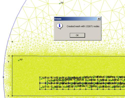
For most animations there were 90 (some 130, others 75) frames (and thus simulations) that were made. So all in all it took quite a bit of computing time. Glad I didn't have to do it manually using a slipstick... 
One thing I've found is that when FEMM is computing all this stuff, it's best to leave the PC alone; any activity (browsing, accessing the HDD) can cause FEMM to stop saving the data... i.e. it computes (and takes all of the times that goes with that) yet instead of saving 4+MB .BMP images of each frame, it saves tiny empty files of 58 bytes... Not sure what is the cause of this problem (FEMM or Windows), but it has taken me by surprize a few times. So I normally start the script, verify that everything is working properly and then leave the PC alone till it's finished. Peter. |
||||
| SparWeb Senior Member Joined: 17/04/2008 Location: CanadaPosts: 196 |
[quote=gwatpe]Was this design continued to a finished test unit? [/quote] Not at all. It was simply a model that conveniently left enough room to display the fields. Two years ago I put together a "how it works" paper on these axial flux alternators. More as a means to fix the facts in my own mind, but in the end it was easy enough to illustrate and make the text "readable". AXIAL_FLUX_HowItWorks_V1a.pdf (780 kB) I like to pass it on to new members on Otherpower, and it's also made the rounds on the internet. I've found it in Dutch and Italian. (The Italian is a teacher who asked for permission to translate it and use it in his course material; I was totally flattered). While illustrating it, I almost got totally side-tracked with the 3D simulation. I had a picture in my mind where I could show the intensity of the field, seeing "inside" those holes for the stator coils. Looking at the bright magenta colours in some coils would show peak flux linkage in those coils, where the other coils, between poles, would have increasing or decreasing flux. Then I could go on about peak voltage, etc., etc. It just became too complicated to draw. Steven T. Fahey |
||||
| SparWeb Senior Member Joined: 17/04/2008 Location: CanadaPosts: 196 |
[quote=Dinges]Can't complain of course, FEMM is a sheer joy to work with, incomparable to some other (mechanical) finite element packages I worked with in the past. [/quote] Don't forget to mention it's FREE!
Wow 300,000 nodes. Apart from making the picture pretty, (smooth curves etc.) do you get significantly different results over, say a 50,000 node mesh? I can't say much about the missing output images. I've never tried to use it that way. In fact I haven't explored the "lua scripts" at all. I have all the CAD I need to creat geometry in a minute and import the DXF that way. I prefer to pull a screen shot after arranging the integration windows so that all the data is captured in the one still image. My other trouble is that my home computer is an obsolete desktop from work. Now that I have a dual processor workstation in the office, I can't shake the desire to run FEMM while at work. C'mon, just a little won't hurt... Steven T. Fahey |
||||
| Dinges Senior Member Joined: 04/01/2008 Location: AlbaniaPosts: 510 |
[quote=Steven]Don't forget to mention it's FREE![/quote] ...yes, that was the main reason none of the 3D packages fitted the 'suitability' criterium :) [quote=Steven]Wow 300,000 nodes. Apart from making the picture pretty, (smooth curves etc.) do you get significantly different results over, say a 50,000 node mesh?[/quote] Not really, mostly the only improvement is prettier pictures. In rare cases (e.g. simulating for cogging) the high resolution is actually needed to make the noise smaller than the actual signal (cogging) we want to see. But that's just about the only task that really needs it. I'm prepared to pay the price (computing time) just for prettier pictures though. [quote=Steven] I have all the CAD I need to creat geometry in a minute and import the DXF that way. I prefer to pull a screen shot after arranging the integration windows so that all the data is captured in the one still image.[/quote] That's how I did it in the past too, but by cleverly defining groups (groups of items, e.g. magnets) which you can easily move using commands in the LUA script, it takes a LOT of work out of it all. To the point that making such animations actually becomes a drag instead of a challenge. Also, when you play around with LUA, you'll notice that the FEMM user interface is just a very thin shell that shields the user from these commands... Not only that, but using LUA you get access to more and more powerful commands than the user interface has. [quote=Steven]I like to pass it on to new members on Otherpower, and it's also made the rounds on the internet. I've found it in Dutch and Italian. (The Italian is a teacher who asked for permission to translate it and use it in his course material; I was totally flattered).[/quote] I've also stumbled by accident a few times upon your 'how it works' paper in various places on the web...
And I understand your feelings. About two weeks ago I was googling for something when I stumbled upon the decogging tutorial I wrote in a German wind forum (www.kleinwindanlagen.de). Must say I was flattered to see it criticized there and meeting with approval. It's nice to know that all the effort that you've put into writing it is helping others. It's the main reason for publishing the FEMM animations here too... the work has already been done, I've benefitted from it myself, so in that sense it served its purpose; I can hide the animations on my harddisk but by publishing it, hopefully one or two others can learn from it too with no extra cost to myself. It's not Nobel-prize winning stuff, but I think it has its merits. Peter. |
||||
oztules Guru Joined: 26/07/2007 Location: AustraliaPosts: 1686 |
"JEALOUSY ALERT" Sigh...., the superfemm Dutchman has his own spot on Hughs web page.... I've been usurped! Well deserved too Dinges, it was excellent work  and more than deserves a place in the wind annals of the world. and more than deserves a place in the wind annals of the world.
........Dinges claim to fame It looks like Hugh has translated his book for him too (Windturbine Receptenboek nederlands talig ) I knew him before he was famous. 
Congrats to Glen as well (he was already famous) , the Backshed has a whole block of honorable mention...... Imsmooth has claimed a spot as well with.... "another chainsaw fanatic".... I knew him before he was famous too....
....oztules Village idiot...or... just another hack out of his depth |
||||
