
|
|
Forum Index : Microcontroller and PC projects : Thinking about a new Pico PCB design for integrating into a keyboard
| Author | Message | ||||
| Mixtel90 Guru Joined: 05/10/2019 Location: United KingdomPosts: 5742 |
Do you think putting stopper resistors on the sync signals, right next to the pins, might reduce the 60Hz? Mick Zilog Inside! nascom.info for Nascom & Gemini Preliminary MMBasic docs & my PCB designs |
||||
| Volhout Guru Joined: 05/03/2018 Location: NetherlandsPosts: 3558 |
Not sure Mick, I expect the 60Hz hum as result of power supply ripple especially if you have a half white half black screen. Each io pin of the rgb drives 12mA, synchronus, 36mA 60Hz load at 3.3V depending how good the power system is, that may pose a problem( the linear reg will be superior). The ringing I discussed earlier will only be passing into the audio when sync and filtered audio are close to each other. But the ringing depends also on the cable, and may cause spikes yhat exceed 3.6V at the pico pins. That is more what worries me. And you need a good scope to see this. PicomiteVGA PETSCII ROBOTS |
||||
| phil99 Guru Joined: 11/02/2018 Location: AustraliaPosts: 1799 |
It may be possible to minimize the effects of ripple and noise on the 3.3V supply by clipping the PWM with a resistor and 2.7V zener before the filter. This will reduce the output a bit, so a transistor may be needed to boost it back up. Experiment on a breadboard to see if the transistor is needed. The collector resistor could be supplied from 5V via a RC filter to avoid adding any more noise. If you can find the room for all of this. PS. A 100pF cap across the zener will prevent it adding its own noise. |
||||
| Mixtel90 Guru Joined: 05/10/2019 Location: United KingdomPosts: 5742 |
Volhout did a similar thing a while ago, using a 3K3 resistor and a normal silicon diode to limit the PWM prior to filtering. It seems to work well (and will even drive 32R headphones, but not loudly). Output is a little limited, of course, but two diodes in series would limit to about 1.3V which should still give a useful reduction in noise. I don't want to add transistors unless I *really* have to. It's for mechanical reasons - I can't spare the board height! Likewise, capacitors have to be at the back of the board or have to lie down horizontally (or be SMD types, which wouldn't add to my popularity). I'm happy with line output level for this project so I think it can be done purely with passives. Mick Zilog Inside! nascom.info for Nascom & Gemini Preliminary MMBasic docs & my PCB designs |
||||
| Mixtel90 Guru Joined: 05/10/2019 Location: United KingdomPosts: 5742 |
Provisional circuit. I'm looking for comments on the audio part, in particular, as filter designing isn't really my field. In theory it starts with limiting the PWM to about 1V3 to reduce the noise. That's followed by a high pass to reduce 60Hz from the VGA side. Following that there's a low pass to reduce the PWM and computer hash. Then there are DC blocking caps with bleed resistors (actually, I don't need those... Too late, they're on the PDF. :) ). The idea is to drive 32R headphones or line output without having to mess with links or volume controls. Apart from that, I'm pretty happy with the board now. Swapping the audio jack and PS/2 socket has separated the audio out from the PS/2 lines a bit, which should help a little more. I've added a SMD reset button too. Fiddly to get to, but at least it's there if someone wants it. Mick Zilog Inside! nascom.info for Nascom & Gemini Preliminary MMBasic docs & my PCB designs |
||||
| Volhout Guru Joined: 05/03/2018 Location: NetherlandsPosts: 3558 |
Can you share the pdf? I have been playing with the audio a bit, and totally undetstand now why you hesitate to add filters and transistors. For a headset simple 470 ohm resistors work fine. No filter. It is only when you want to use it as line-out to a stereo amplifier that you need to get rid of the 44khz. Edited 2022-05-03 23:15 by Volhout PicomiteVGA PETSCII ROBOTS |
||||
| Mixtel90 Guru Joined: 05/10/2019 Location: United KingdomPosts: 5742 |
OOPS sorry - I meant to. :) PicoMite VGA Keyboard Circuit.pdf Mick Zilog Inside! nascom.info for Nascom & Gemini Preliminary MMBasic docs & my PCB designs |
||||
| Volhout Guru Joined: 05/03/2018 Location: NetherlandsPosts: 3558 |
Hi Mick, The pico pins need to feed 470 ohm resistors to the stacked diodes, remove the capacitors C2. The bleeder resistors at the output kan be 10k or 100k. 15nf may give acceptabe audio, but does not reject 44khz much. I needed a transistor, as active filter, to get a filter steep enough for audio to pass, an 44khz to be rejected to 1% Bav99 is a double diode that many may still be capable of soldering. Smt. If you dont mind a bit of crosstalk berween l and r audio, you can use 3 diodes in stead of 4. One to l, one to r, an a common one to ground. Edited 2022-05-03 23:27 by Volhout PicomiteVGA PETSCII ROBOTS |
||||
| Mixtel90 Guru Joined: 05/10/2019 Location: United KingdomPosts: 5742 |
I could use a RLC filter, I suppose, providing I can use axial inductors. That gives values of 100uH, 220uH, 470uH or 1mH really. The 470uH and 1mH are getting slightly bulky, but may be ok. It might give a better filter shape, even with just LC off the PWM pin. Not bothered about the extra diodes. Most people will have 1N4148s kicking about. :) A bit of crosstalk can be good with headphones. It gives a stronger centre image. I'd perhaps better try that. Edited 2022-05-03 23:58 by Mixtel90 Mick Zilog Inside! nascom.info for Nascom & Gemini Preliminary MMBasic docs & my PCB designs |
||||
| Volhout Guru Joined: 05/03/2018 Location: NetherlandsPosts: 3558 |
Hi Mick, I just spend an hour measuring the audio, and it is difficult (read: needs big circuit) to get performance. Just some pictures to paint the picture: I copied a track from a CD onto SD card, Some guitar music from Harrry Sacksioni, a Dutch guitar player, accompanied by an orchestra. This shows dynamic and wider audio spectrum. Listening on a headset (did not dare my audio setup to this experiment). 1/ The PWM signal from the picomite 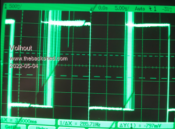 The PWM is clearly visible. If applied to a headset (470 ohm series), it actually sounds good. But you can clearly see that the 44kHz is dominant,Not good for a stereo amplifier..... 2/ The audio filtered by 470ohm and 47nf (actually 50nf). 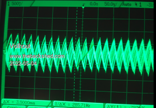 Somewhere hidden in the trangular 44kHz waveforms is the hidden audio information. With this filter the 44kHz is still as large as the hidden audio. 3/ The audio filter (with transistor) I designed gives a much better signal. The 44kHz is still visible (the waveform is thicker than a noisefree waveform) but you can clearly see this is audio (this is on a different timebase scale). 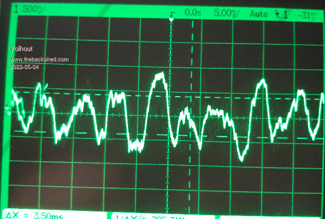 But there are all kinds of noise and rattle audible in the audio. I have been able to lower the "random" rattle �by using. OPTION POWER PWM ON But there was still a repeating rattle that is caused by the pico and sd card. I am not sure if it is the current the SD card uses, or the current the pico uses to read the SD card, but it shows a a lot of noise (in bursts) on the 3V3 and actually also shows on the 5V (due to load variations ?).These bursts are not present when you play tone, or when you stop the wave play. 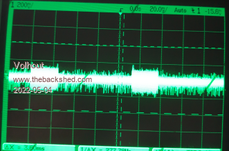 I have added filters in both 3V3 and 5V to cope with it, but all in all I am not really happy with the size of the circuit. Lots of components. This is a difficult beast to tame. Maybe the MCP1700 (I will order a few) will improve, probably on 3V3, but the 5V may still be noisy. Maybe it is better to design the audio circuit around a dual opamp (active filter + low impedance out) powered from 5V. Most opamps have good rejection of the noise on the power rails. And soldering 2 transistors and 2 resistors is not much different from an 8 pin DIL socket. And it saves RC filter in the 5V (electrolitic cap.) P.S. I will look into your idea of the LC filter (or 44kHz trap), but am not sure the pico pins are safe for that. For the filter to be adequate, it needs a reasonably high Q factor. Which means it will cause spikes on the pico pins when you insert or extract the headset. I'll ivestigate Edited 2022-05-04 04:26 by Volhout PicomiteVGA PETSCII ROBOTS |
||||
| Mixtel90 Guru Joined: 05/10/2019 Location: United KingdomPosts: 5742 |
The SMPS is flippin' awful anywhere near audio. lol The linear reg certainly makes a difference. That 44kHz is nasty, isn't it? I wonder if a notch filter centered on there might be the answer? Mind you, it would have to be active to be useful. :( On your test system, have you got the supply to the SDcard filtered? Mick Zilog Inside! nascom.info for Nascom & Gemini Preliminary MMBasic docs & my PCB designs |
||||
| Volhout Guru Joined: 05/03/2018 Location: NetherlandsPosts: 3558 |
Hi Mick, I have the cap at the SD card, but not the 2.2 ohm. Maybe that makes a difference. I have looked into the LC filter, and I think I may have found something usable. It is a low pass filter with a trap frequency at 44kHz. from the pico pin you go with 180 ohm to the filter. Termination with 220ohm and 470 ohm. The 32 ohm headset goes parallel to the 470 ohm.. With high impedance, and headset the filter shape remains good. The inductor is 1mH (the 10 ohm is it's internal resistance, it is an estimate, do not add a resistor, just the inductor part). Tried smaller values but that does not work. Larger would be better, but harder to get I guess. The 12nF capacitor is tuned to get the 44kHz centered. Both 1mH inductor and 12nF capacitor need to be fairly accurate for best performance (5%). The other capacitors do not matter much. I do not have the components in my bin, and can only get to components next week. 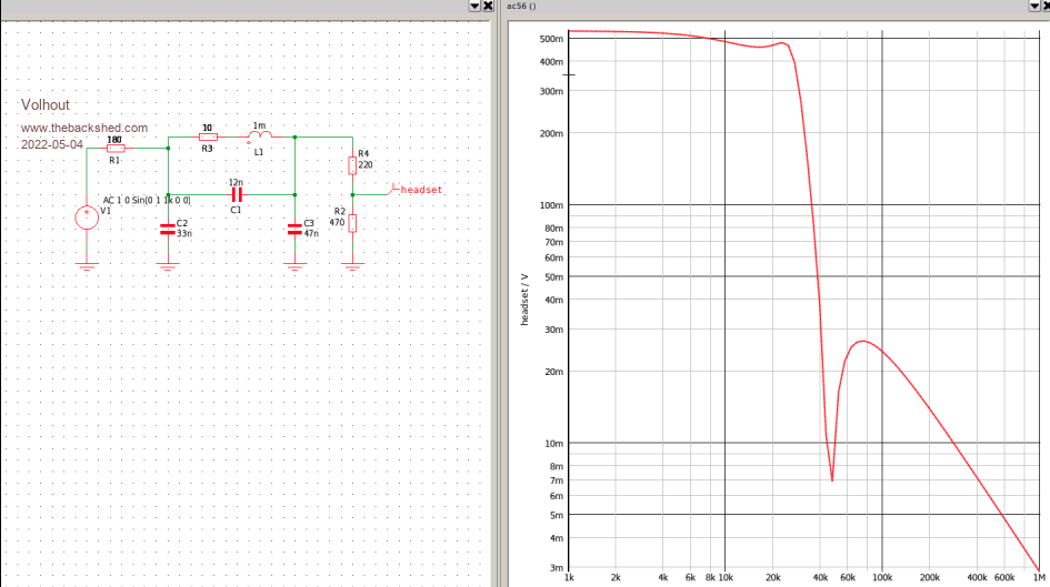 PicomiteVGA PETSCII ROBOTS |
||||
| Volhout Guru Joined: 05/03/2018 Location: NetherlandsPosts: 3558 |
Mick, I will try the filter with 1.5mH inductor (not 1mH), and 8.2nF (not 12nF) since that gives the best overall performance. The other components stay the same. Ordering components now....Also MCP1700's (if I can find them). Actually I am quite excited about this. This may be the best simple solution overall. Volhout Edited 2022-05-04 05:24 by Volhout PicomiteVGA PETSCII ROBOTS |
||||
| Mixtel90 Guru Joined: 05/10/2019 Location: United KingdomPosts: 5742 |
That's a rather nice curve. :) I can get 10% axial ferrite inductors easily enough here. Not a bad size - 3mm dia x 6.5mm long right up to 1mH. Unfortunately they don't stock anything above 1mH, but I can put a couple in series. Their 1mH axial has a resistance of 30R, if that helps, and 470uH is 13R. I might get an assorted bag of these as I've not got any little inductors apart from the odd one. EDIT: Hmmm.... 8.2nF and 12nF aren't all that common. No problem with 6.8nF, 10nF :) Edited 2022-05-04 07:37 by Mixtel90 Mick Zilog Inside! nascom.info for Nascom & Gemini Preliminary MMBasic docs & my PCB designs |
||||
| phil99 Guru Joined: 11/02/2018 Location: AustraliaPosts: 1799 |
"P.S. I will look into your idea of the LC filter (or 44kHz trap), but am not sure the pico pins are safe for that. For the filter to be adequate, it needs a reasonably high Q factor. Which means it will cause spikes on the pico pins when you insert or extract the headset." If the LC trap is used in series with the 470R the current will be low and thus spikes will also be small. The clipping diodes will make them even smaller The Pico PWM is always low impedance (40 - 50 ohms) high or low so transients are safely shunted to + or -. |
||||
| gob33 Newbie Joined: 26/02/2018 Location: FrancePosts: 6 |
You have the TAUON-PC. Its AllWinner H3 board is removable and you can install Orange Pi Lite, Orange Pi PC, Raspberry PI Zero W, C-Sky board.  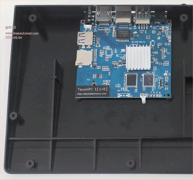 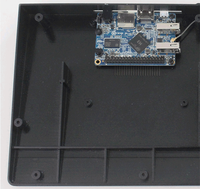 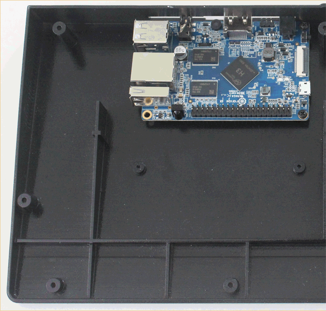 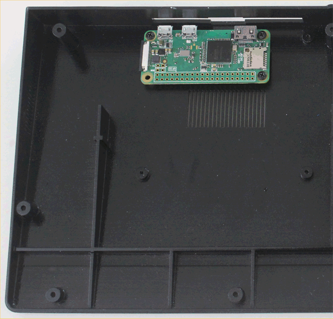 |
||||
| Mixtel90 Guru Joined: 05/10/2019 Location: United KingdomPosts: 5742 |
Well, yeah, but it's not a mechanical keyboard, it costs $85 including carriage, it looks like it might be USB (it doesn't say, but that's not supported anyway) and it doesn't run MMBasic. :) They don't advertise the empty keyboard. Is it available? Edited 2022-05-04 20:07 by Mixtel90 Mick Zilog Inside! nascom.info for Nascom & Gemini Preliminary MMBasic docs & my PCB designs |
||||
| Amnesie Guru Joined: 30/06/2020 Location: GermanyPosts: 384 |
For me, every keyboard which is NOT a mechanical keyboard, is pure junk. I am speaking of experience here. This is the reason I would never buy a raspberry pi 400 with it's built in toy keyboard. Maybe this is just my engineering habit, but things should be done properly, long lasting ... If I want to use something excessively, this won't last long.. Don't to mention that almost all cheap keyboards don't laser engrave the keycaps. �  Edited 2022-05-04 20:53 by Amnesie |
||||
| gob33 Newbie Joined: 26/02/2018 Location: FrancePosts: 6 |
According to the Tauon Forum, selling the bareboard keyboard only was not a valuable option for them as the price is low. I agree the shipping cost could be more adapted to the buyer country. You get the low quality corresponding to the price, this is not mechanical and I dont know any commercial mechanical keyboard tall enough to incorporate a board. If you design a custom keyboard for pico integration, then molding it is far too expensive. Which leads you to 3D print it for every buyer. This is not viable and you should do compromises. An interview with the creator of the Tauon PC-1, Volodymyr Mishin Edited 2022-05-05 00:08 by gob33 |
||||
| Tinine Guru Joined: 30/03/2016 Location: United KingdomPosts: 1646 |
I would consider buying a Tauon and throwing the keyboard away if it had something better than a 1GHz processor and more memory. Why such a dog? Craig |
||||
