
|
|
Forum Index : Microcontroller and PC projects : Shall I call this one Gemini?
| Author | Message | ||||
| Mixtel90 Guru Joined: 05/10/2019 Location: United KingdomPosts: 5730 |
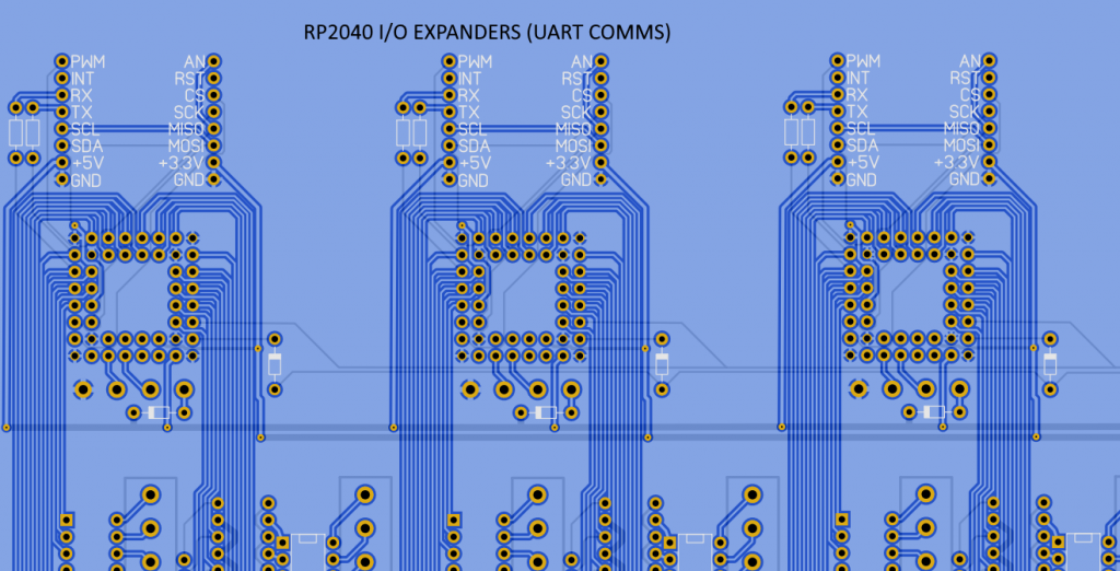
Version 0.2 will now accept either the TO220 or SOT versions of the regulator - correctly connected! The supply to Pico 1 has now got a more versatile circuit, so it can use its SMPS and can be fed from an external 5V supply, as it can now be isolated from the 3V3 regulator. As mentioned earlier, GP4 and GP5 were taken off the SD card socket and replaced by GP6 and GP7. GP4 and GP5 are now directly on the GPIO header, with no internal connection, giving access to COM2. More info to follow. Mick Zilog Inside! nascom.info for Nascom & Gemini Preliminary MMBasic docs & my PCB designs |
||||
| Rickard5 Guru Joined: 31/03/2022 Location: United StatesPosts: 328 |
I been thinking about this, and I promise I'm not drunk, Just Simple minded �I been thinking hard about how to Scale up the number of picos in the Cluster, if I understand it correctly, I can use SPI to communicate between Pico 1 and Pico 2 and use SPI to communicate between Pico Pear Boards? I threw together a quick diagram to illustrate my thinking: 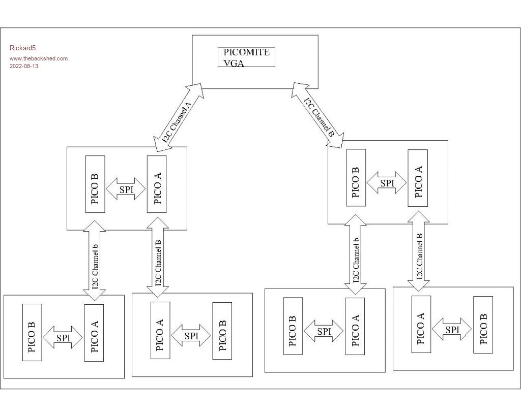 My Thinking is not only would this give me tons of GPIO to mess with, But break down Large Complex projects in to sub Processes each with it's own Pico. �for example if I were to get back in to Racing Slotcars or R/C and I was inclined to build a better Motor Dyno, I could dedicate one Pico to manage the Acceleration of the test motor and log Voltage over time. another pico could monitor and log Motor RPM, RPM over Time and another could monitor and log �Feedback voltage during Dynamic Breaking , and so on though all the test points and then pass that data up the chain to the next lever that process all that data, and pass it up to a Master control program on the top level Picomite VGA that acts solely as a front end processor and I/O controller, I also could do something I've always wanted to do and maybe build a Wind Tunnel the same way :) does this seam Reasonable ? Thanks Guys Edited 2022-08-13 16:07 by Rickard5 I turned the volume on the monitor to max and could hear sound. Thanks Stanleyella |
||||
| Mixtel90 Guru Joined: 05/10/2019 Location: United KingdomPosts: 5730 |
IMHO there are better ways, and less complex. You could use a single I2C bus for everything, giving each slave an address. Usually only for short distances. You could use SPI from the PicoMite VGA with a CS pin for each slave. That would be very fast and doesn't need slave addresses, but the number of slaves is limited by the number of CS pins available. It's also short distance only. It's also possible, with some fiddling, to multi-drop using a COM port. You could do a proper RS-485 link between everything. That has the advantage that long distances are possible. None of these arrangements needs a "tree" arrangement and only a single port is needed for each device. Mick Zilog Inside! nascom.info for Nascom & Gemini Preliminary MMBasic docs & my PCB designs |
||||
| lizby Guru Joined: 17/05/2016 Location: United StatesPosts: 3015 |
I'm not sure about the kind of scalability you're looking for, but why not straight multi-drop serial, call and response? This is pretty trivial.  PicoMite, Armmite F4, SensorKits, MMBasic Hardware, Games, etc. on fruitoftheshed |
||||
| Mixtel90 Guru Joined: 05/10/2019 Location: United KingdomPosts: 5730 |
The master RX pin should have a pull-up and the diodes on the slaves should be pointing down. Their TX pins will normally be high, and the master RX pin will be pulled high. Each slave can then pull the master RX pin low via its diode. The master TX pin can just be hard wired to all the slave RX pins as they all receive the same data (each one has an address). You can have an optional pull-up. All the RX pins are high impedance. Mick Zilog Inside! nascom.info for Nascom & Gemini Preliminary MMBasic docs & my PCB designs |
||||
| Rickard5 Guru Joined: 31/03/2022 Location: United StatesPosts: 328 |
Lance and Mick Thank you for explaining that, I've been really Wound up with my Pear. While I don't really know how too properly utilize it's potential yet, I see it's potential. I'm gonna try to play with serial stuff on the breadboard, and if I have any other Questions I'll start a new thread Thanks Again ww I turned the volume on the monitor to max and could hear sound. Thanks Stanleyella |
||||
| lizby Guru Joined: 17/05/2016 Location: United StatesPosts: 3015 |
Rick--I've enable serial connection between Pico1 and Pico2 on the Pear by connecting the header pins D to 2 and C to 1, but haven't tested it yet--I'm stuck on getting a rotary encoder module working with a display on the SSD1306 128x32 LCD. I've got the switch on the encoder working, but not turning the post--despite the fact that I'm using Peter's code which I had working before on a different setup. Once that is working I'll want your help in figuring out how to use that data to position a stepper motor with the A4988 module you linked to earlier. PicoMite, Armmite F4, SensorKits, MMBasic Hardware, Games, etc. on fruitoftheshed |
||||
| Tinine Guru Joined: 30/03/2016 Location: United KingdomPosts: 1646 |
 Rigorously tested/proven (460K BAUD)as slaves to the Propeller P2. |
||||
| Rickard5 Guru Joined: 31/03/2022 Location: United StatesPosts: 328 |
Sorry but the notation in the Bill of Materials is driving me nuts because I just have never seen this but is R1& R14 - 2R2 = 2.2 ohm or 2.2k ohm and is R6, R9, & R12 �220R = to 220 ohm or 220k Ohm ? Edited 2022-08-14 23:12 by Rickard5 I turned the volume on the monitor to max and could hear sound. Thanks Stanleyella |
||||
TassyJim Guru Joined: 07/08/2011 Location: AustraliaPosts: 5905 |
It's the international standard IEC 60062:2016 Also called RKM code. Replace decimal point with multiplier. 2.2 ohms is written as 2r2 2.2k ohms will appear as 2k2 Decimal points can easily get lost so I prefer it to the 'old way' VK7JH MMedit MMBasic Help |
||||
| Mixtel90 Guru Joined: 05/10/2019 Location: United KingdomPosts: 5730 |
Your main worry, Rikard, is that you DON'T use the voltage reg as it's shown on the PCB as the connections are wrong! See my earlier posts. Resistors are easy to sort out. :) As Jim says, decimal points are easy to lose, especially where text is fine or on small screen printing. The method I used leaves no room for error in the existence of a decimal point. Mick Zilog Inside! nascom.info for Nascom & Gemini Preliminary MMBasic docs & my PCB designs |
||||
| Rickard5 Guru Joined: 31/03/2022 Location: United StatesPosts: 328 |
Good Deal, Thanks Guys. someday I'll finish this board :) then I won't know what to do with my self, I'll probably sit around and go off topic about why is it that we only get handful of the Royle Family Episodes, but they'll torture us with Coronation Street for 50 years! I turned the volume on the monitor to max and could hear sound. Thanks Stanleyella |
||||
| lizby Guru Joined: 17/05/2016 Location: United StatesPosts: 3015 |
That's what I get for copying an image from the 'net without understanding it. This one looks like what you're saying.  PicoMite, Armmite F4, SensorKits, MMBasic Hardware, Games, etc. on fruitoftheshed |
||||
| Mixtel90 Guru Joined: 05/10/2019 Location: United KingdomPosts: 5730 |
Yep, that's the idea. :) It's a very neat scheme, but you need a protocol that includes addressing for the slaves and (preferably) some sort of error checking. The master can talk to all the slaves at once if you specify a global address, but the slaves can only reply to specific messages from the master if you want to avoid bus collisions. This is one of the arrangements that I looked at (and incorporated into the hardware) for the MPC. One day I might even be able to afford to test that. Mick Zilog Inside! nascom.info for Nascom & Gemini Preliminary MMBasic docs & my PCB designs |
||||
| lizby Guru Joined: 17/05/2016 Location: United StatesPosts: 3015 |
I finally got everything soldered on with the pear, except for the buzzer and sound, and green is the only color I have on my VGA monitor. Version is PicoMite 5.07.05b15. CLS RGB(red), CLS RGB(blue), and CLS RGB(green) all give me a green like the olden days. Is this what I should expect, or have I likely got something wrong? Also, the first 1-1/2 characters are off the left hand edge of the monitor. Is there a setting I can use to adjust this, or might it be a monitor adjustment? PicoMite, Armmite F4, SensorKits, MMBasic Hardware, Games, etc. on fruitoftheshed |
||||
| Mixtel90 Guru Joined: 05/10/2019 Location: United KingdomPosts: 5730 |
The video circuit is only the simplified one with clamping diodes - there's nothing to go wrong really. If you are only getting green then it looks like some circuits are either open circuit or shortrd to gnd. I assume you have a test meter? With the power off check the resistances between: pin GP18 and VGA pin 3 (220R) pin GP19 and VGA pin 2 (680R) pin GP20 and VGA pin 2 (330R) pin GP21 and VGA pin 1 (220R) Also check the polarity of D2, D3 and D4. It's correct on the PCB (+ towards the Pico). You are getting a stable display so the synch signals will be ok. I assume that that is the PicoMite VGA firmware and not the ordinary PicoMite? ;) The missing LH characters has to be a timing issue, either a monitor adjustment if that's possible or the bersion of MMBasic doesn't agree with your monitor. It looks like an overscan issue. There are no adjustments in hardware as all timing is handled by MMBasic. Have you a different monitor you can try? Have you tried that version of MMBasic on that monitor before? Mick Zilog Inside! nascom.info for Nascom & Gemini Preliminary MMBasic docs & my PCB designs |
||||
| Volhout Guru Joined: 05/03/2018 Location: NetherlandsPosts: 3534 |
Looks lii e the 220 ohm resistors have the wrong value. PicomiteVGA PETSCII ROBOTS |
||||
| Mixtel90 Guru Joined: 05/10/2019 Location: United KingdomPosts: 5730 |
red-red-orange instead of red-red-brown? I wonder... Mick Zilog Inside! nascom.info for Nascom & Gemini Preliminary MMBasic docs & my PCB designs |
||||
| lizby Guru Joined: 17/05/2016 Location: United StatesPosts: 3015 |
Yes, VGA firmware version--I had intended to say that. Resistor values check out with the DVM--picomite pin to VGA connector pin. Diodes D2, D3, D4 all have the ring towards the Pico--but I used BAT85s--would that be a problem? I don't have the LM4040 fitted--could that be the issue? I haven't used this monitor with PicoMiteVGA before. I'll see if I can find and finish the PicoStick VGA. And I'll try a different monitor (if my other ancient one has VGA--I think it does). PicoMite, Armmite F4, SensorKits, MMBasic Hardware, Games, etc. on fruitoftheshed |
||||
| Mixtel90 Guru Joined: 05/10/2019 Location: United KingdomPosts: 5730 |
The change in diodes will limit your maximum video voltage outputs to about 0.4V rather than 0.7V because the BAT85 is a Schottky type. As green seems to be working it *may* not be a problem, but it will be dimmer than expected. I'd cut them out, I think. Although you are then over-driving the VGA inputs a bit the monitor will probably be able to handle it ok and you can always either change the resistor values or put the right diodes back.. Did you check that GP18 and GP21 aren't shorted to gnd? You may have to test that using reverse polarity on your meter to avoid it seeing the diodes. Might be better with the PicoMite unplugged too. The LM4040 won't make any difference. Mick Zilog Inside! nascom.info for Nascom & Gemini Preliminary MMBasic docs & my PCB designs |
||||
