
|
|
Forum Index : Microcontroller and PC projects : PWM to +/- 10V
| Author | Message | ||||
| PeterB Guru Joined: 05/02/2015 Location: AustraliaPosts: 639 |
Craig. To understand how op-amps work you need to understand 3 very simple facts. 1. Ohm's Law i = E/R 2. The current into an op-amp is zero 3. An op-amp will do everything in it's power to make the two input voltages equal. If you understand these then using op-amps is fairly simple. In this application the op-amp input is offset above zero so that makes calculations a bit more difficult. I had to resort to simultaneous equations for the first time in many years. But the difficulty is just accepting that they obey simple rules. It's not as hard as it looks. Peter |
||||
| Mixtel90 Guru Joined: 05/10/2019 Location: United KingdomPosts: 5727 |
https://www.falstad.com/circuit/ is fun for stuff like this. :) Mick Zilog Inside! nascom.info for Nascom & Gemini Preliminary MMBasic docs & my PCB designs |
||||
| Tinine Guru Joined: 30/03/2016 Location: United KingdomPosts: 1646 |
Sure....the only thing I'm not grasping at this point is the voltage divider. Looking at the original circuit, a 50% duty cycle of 5v would be 2.5v on the inverting input but the 30K + 20K divider would result in only 2v on the non-inverting input....what gives? Many thanks, BTW �  Craig Edited 2022-05-12 17:25 by Tinine |
||||
| Tinine Guru Joined: 30/03/2016 Location: United KingdomPosts: 1646 |
I'm thinking....drop the fixed-resistor divider and stick my 20-turn, 50K trim-pot in there instead(???) Craig |
||||
| PeterB Guru Joined: 05/02/2015 Location: AustraliaPosts: 639 |
Using your original circuit we have. For Ein = 5V we have 3V across the 10k. With zero current into the op-amp, the voltage across the 40K will be 12V. That voltage is -ve and wrt 2V giving -10V. With Ein = 0V we have 2V across the 10k giving a voltage across the 40k of 8V and since this is wrt 2V we get 10V. There is a problem getting current flowing in the correct direction. It can look like Custer's last stand. Peter It is important to accept that the two inputs are forced to be 2V. Edited 2022-05-12 17:47 by PeterB |
||||
| Tinine Guru Joined: 30/03/2016 Location: United KingdomPosts: 1646 |
Getting there Craig |
||||
| phil99 Guru Joined: 11/02/2018 Location: AustraliaPosts: 1783 |
Just to make your head spin a little faster, another way to view PeterB's answer (still using the original 5V version) is:- If the voltage divider = 1/2 * 5V and the inverting gain is 4 (40/10) the output will swing + and - 10 V with respect to that. ie -7.5 to +12.5 (or would with a higher supply) Thus the voltage at the noninverting input needs to be reduced to compensate. The noninverting gain is 5 (10 + 40)/10 so to drop the output by 2.5V the input is reduced by 0.5v (2.5/5) to 2V. |
||||
| Tinine Guru Joined: 30/03/2016 Location: United KingdomPosts: 1646 |
So, to summarize, for the 3.3v PWM, I get my gain of 6 by using 60K feedback and to set my null point, I can drop the existing 30K+20K divider for a 50K, 20-turn pot  [anticipates being shot down in flames]  Craig |
||||
| PeterB Guru Joined: 05/02/2015 Location: AustraliaPosts: 639 |
Craig I hate to admit it but phil's explanation is very elegant. With luck he will fall off his calculator and break his leg.  However, trim pots are a bad idea because they are unreliable, expensive etc. I have always preferred using software to correct offsets etc but that may be because I designed the hardware and the flow chart but left most of the software to the younger blokes. Do you understand op-amps yet? Peter |
||||
| Tinine Guru Joined: 30/03/2016 Location: United KingdomPosts: 1646 |
Oh, software offsets are the norm for me. It's just that I'd sooner have a single set-and-seal trimpot than a cluster of fixed-resistors (ugly). The software-trim will always be there. I have enough understanding to make me excited to get to my breadboard because I like to see real-world values. At some point, I need to get-to-grips with Volhout's, more sophisticated filtering because it is obviously done for a reason |
||||
| Mixtel90 Guru Joined: 05/10/2019 Location: United KingdomPosts: 5727 |
Have a look at that software, Craig. It's a breadboard where you can't blow things up. :) You don't have to use the listed circuits, just select blank and draw your own. Mick Zilog Inside! nascom.info for Nascom & Gemini Preliminary MMBasic docs & my PCB designs |
||||
| Tinine Guru Joined: 30/03/2016 Location: United KingdomPosts: 1646 |
I did, and it's really cool. Funnily enough, when I searched for Circuit Simulator, last night, I found one of those lists "the best..." and this is the one that appealed to me. Great minds think alike, eh? Craig |
||||
Chopperp Guru Joined: 03/01/2018 Location: AustraliaPosts: 1032 |
Hi Craig Is there any reason why the circuit can't be wired up as a Schmitt Trigger as per examples in the link above. Lots more examples on Mr Google or Miss DuckDuckGo Anyway, food for thought. Brian ChopperP |
||||
| phil99 Guru Joined: 11/02/2018 Location: AustraliaPosts: 1783 |
I think the output needs to be analogue. The 2n2 cap in the feedback path filters the PWM to get a smooth(ish) variation from -10V to +10V. After some arithmetic perhaps 22nF would be better. Edited 2022-05-12 23:02 by phil99 |
||||
| Tinine Guru Joined: 30/03/2016 Location: United KingdomPosts: 1646 |
Yeah, +/-10V from locked antiphase PWM. Oh heck, Phil, I had some 22nf (well, 22 something) in a 2n2 labeled box and installed them. The machine was flopping around all over the place...couldn't get control of it and in a closed-loop, this could have been any number of things. Drove me nuts for a couple of days Craig |
||||
| Mixtel90 Guru Joined: 05/10/2019 Location: United KingdomPosts: 5727 |
As you increase the size of the capacitor you'll get a less "lumpy" output (it'll be smoother, with less of the input frequency superimposed on it), but it will react more slowly. Always a problem with PWM. It's always a compromise. :( Mick Zilog Inside! nascom.info for Nascom & Gemini Preliminary MMBasic docs & my PCB designs |
||||
| Tinine Guru Joined: 30/03/2016 Location: United KingdomPosts: 1646 |
Definitely a crude DAC but works well for the application. I read the motor position and run the PID 1,000 times/second. The motor response is relatively slow. Craig |
||||
| Mixtel90 Guru Joined: 05/10/2019 Location: United KingdomPosts: 5727 |
I found this on a search. It seems to be ideal: 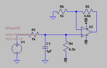 This is the source. A bit of tweaking in Circuit Simulator leads me to: 1k + 6k2 along the top to set the gain. 16k input resistor, 2n2 cap. 97k to -10v (allowing +/- 12v supplies for the op-amp) Edited 2022-05-13 23:17 by Mixtel90 Mick Zilog Inside! nascom.info for Nascom & Gemini Preliminary MMBasic docs & my PCB designs |
||||
| Volhout Guru Joined: 05/03/2018 Location: NetherlandsPosts: 3529 |
Check how much resolution Craig needs. If you have 125MHz pico, and run the PWM at half that (62MHz) and need 16 bit resolution on de analog output, the PWM should run at 1kHz (62MHz / 65536). Then 2N2 is not adequate. If you run 100kHz, you have around 9 bits resolution (620 steps) then 2n2 may work. It is nice to see that you envision 16k series resistor.....my 100kHz PWM filter... 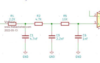 Maybe for goodness sake you should re-calculate R4 to connect to -12V (not -10) Edited 2022-05-13 23:58 by Volhout PicomiteVGA PETSCII ROBOTS |
||||
| Mixtel90 Guru Joined: 05/10/2019 Location: United KingdomPosts: 5727 |
It needs looking at anyway. :) Mick Zilog Inside! nascom.info for Nascom & Gemini Preliminary MMBasic docs & my PCB designs |
||||
