
|
|
Forum Index : Microcontroller and PC projects : PicoMite PLC project
| Author | Message | ||||
| Mixtel90 Guru Joined: 05/10/2019 Location: United KingdomPosts: 5742 |
Ah... :) That's ok then. lol Mick Zilog Inside! nascom.info for Nascom & Gemini Preliminary MMBasic docs & my PCB designs |
||||
| Tinine Guru Joined: 30/03/2016 Location: United KingdomPosts: 1646 |
Heck no. I have the run of my customer's factory in Darwen. Holidays are the best because I'm alone and don't have to put up with the godawful racket from the radio. I mean, what a playground here....I have everything ...even real machines to tamper with �  � � � � Craig Edited 2022-06-02 23:54 by Tinine |
||||
| Tinine Guru Joined: 30/03/2016 Location: United KingdomPosts: 1646 |
I'm the first to harp-on about a shortage of common sense... Yeah, listen to this clown.My pic shows the little DRV8871 H-Bridge that is spec'd @ >24v and >2A? Yeah, look at the size of the driver . There is absolutely no way!No problem for the relatively huge LMD18200 but you don't wanna touch that heat sink (I did ). Such a neat device...I can't destroy it. It dutifully cuts-off on overcurrent (even short-circuit) and over-temp.Not getting too scientific yet but this Chinese clone appears to be right in-line with the spec-sheet.  Craig |
||||
| Mixtel90 Guru Joined: 05/10/2019 Location: United KingdomPosts: 5742 |
That's odd - I was just going to tell you that I started playing with another IO board design this afternoon. It has two L293 4-channel drivers on it wired to terminals, with all inputs including enable pins wired to the PicoMite. There are also two 0-5V analogue inputs and a 5V supply so the board could drive a pair of stepper motors with positional feedback. There are five (there isn't room for eight) uncommited LEDs too, and a fuse that protects both chips. It can be fed from the 24V bus or there is an external supply terminal if you want lower voltage steppers (it can handle up to 36V). Also a useful board for driving up to eight inductive loads as it has the diodes built onto the chip. It all started because I was looking for MOSFETS... �:) That DRV8871 is insane. Love it! lol Oh - also changed the base PCB so that the 24V and GND rails are *much* bigger. In theory an IO board can draw up to 6A, so weedy tracks are not the order of the day. Edited 2022-06-03 05:56 by Mixtel90 Mick Zilog Inside! nascom.info for Nascom & Gemini Preliminary MMBasic docs & my PCB designs |
||||
| Tinine Guru Joined: 30/03/2016 Location: United KingdomPosts: 1646 |
Really odd because I just fished-out one of my L298s....gonna play tomorrow. These drive two motors (or something else) with a continuous rating of 2A. Outputs can be paralleled for a continuous 3.5A. These can be good alternatives to SSRs. I have played with them on hydraulic solenoid valves; once pulled-in, you can PWM them back to something like 1A. I have also used PWM to turn these relatively inexpensive valves to give variable flow. Not as responsive as a true proportional valve but these are 150 quid valves and a true proportional is closer to 2500 quid. Craig |
||||
| Tinine Guru Joined: 30/03/2016 Location: United KingdomPosts: 1646 |
This would be a cool PLC feature to have |
||||
| Volhout Guru Joined: 05/03/2018 Location: NetherlandsPosts: 3558 |
Hi Tinine, This can be ported to PIO in MMBasic. The DMA may not be achievable, but the MMBasic can sample the PIO fifo's around 10000 times per second. Maybe that is sufficient to write an acceptable control algorithm (*). I am not sure if anything faster will be possible in interpreted language (Basic). You may need a compiler for faster processes, since there will be math involved as well. Volhout (*) including math (PID) you should be able to run a single control algorithm (rotary encoder-PID-motor drive with a 1ms tact. You should be able to evaluate if that is sufficient. If you wan to run multiple control algorithms (semi) simultaneaous your tact goes down proportionally (the PIO in your link has a 4 fold quadrature decoder). Edited 2022-06-03 18:24 by Volhout PicomiteVGA PETSCII ROBOTS |
||||
| Tinine Guru Joined: 30/03/2016 Location: United KingdomPosts: 1646 |
I was really hoping for this response 10,000 times/sec is more than fast enough and a motion PID, in MMBasic, is nothing, in terms of code. Most high-performance motion controllers (CNCs) run at 1KHz because it's pointless to exceed this. It wasn't that long ago that 100Hz was the standard. The mechanical elements simply cannot respond. Last year, I closed a motion loop on a MX170 but using ByPic and an external quad decoder/counter. 1KHz was easy BUT motor stability was better at 200Hz Craig |
||||
| Tinine Guru Joined: 30/03/2016 Location: United KingdomPosts: 1646 |
So, this CPU module goes for 2800 quid(!!!!) and doesn't do a darned thing....until you add the 500 quid interface modules. The proposed MultiMite PLC would smoke this rubbish 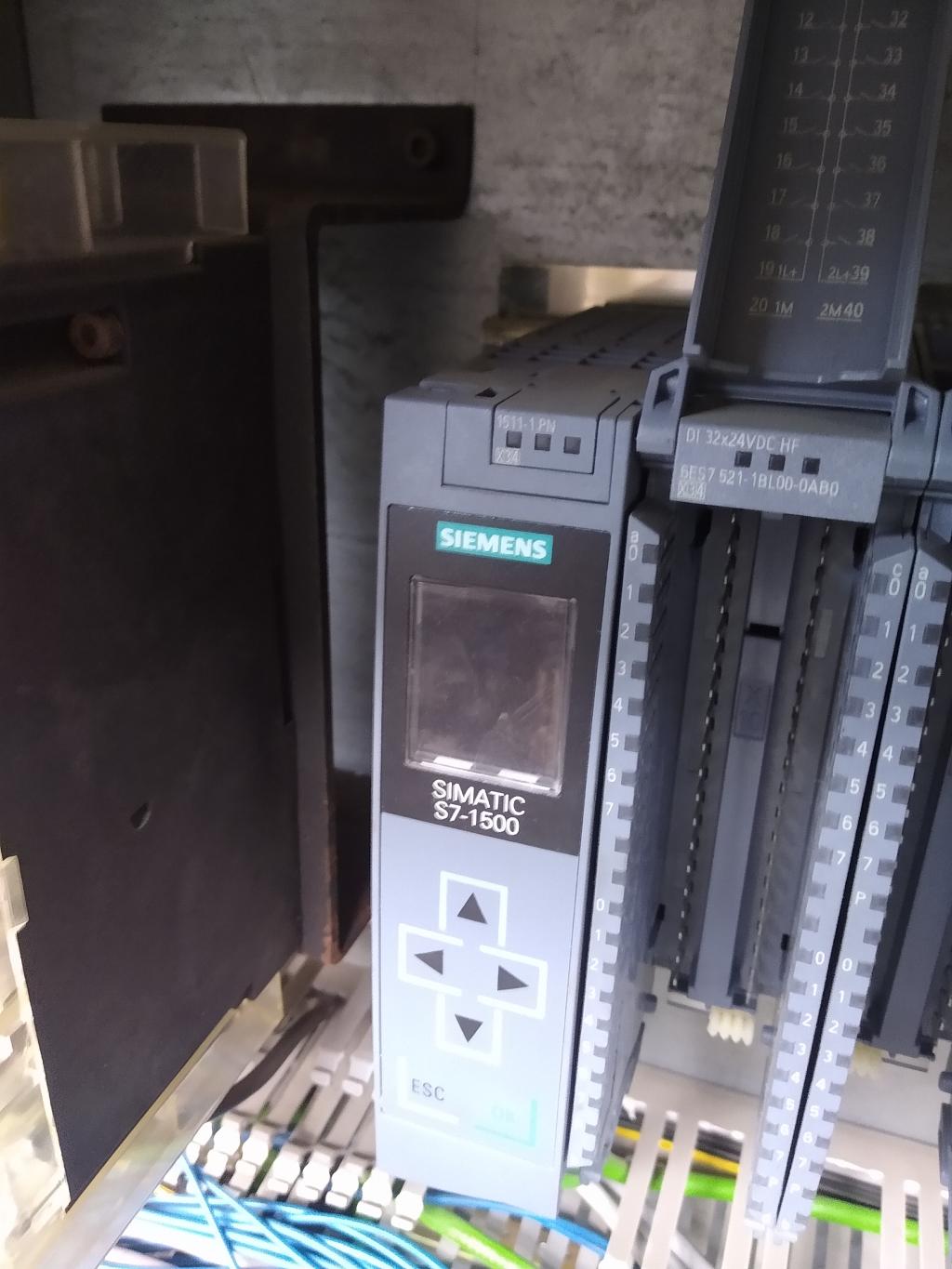 Craig |
||||
| Rickard5 Guru Joined: 31/03/2022 Location: United StatesPosts: 328 |
Mick You sir would be a god worthy of Song and praise if you could develop some kind of pico mite PLC that doesn't suck as much as Allen Bradley Connected Components Workbench or Simatic, I never could figure out Simatic I turned the volume on the monitor to max and could hear sound. Thanks Stanleyella |
||||
| Tinine Guru Joined: 30/03/2016 Location: United KingdomPosts: 1646 |
We're gonna bring Mick out of retirement |
||||
| Mixtel90 Guru Joined: 05/10/2019 Location: United KingdomPosts: 5742 |
I've currently labelled the base pcb (and my directory!) Pico-MPC as there was room to fit that in the corner of the board. :) The SPI concerns me a bit - it says in the manual that the PicoMite acts as the master (it will always produce the clock signal). If that's so then reading into another PicoMite will need some thought as it *mustn't* produce the clock and *must* follow the clock produced by the master. I don't find the manual too clear on this as, I suspect, the worked examples are merely cross-connecting pins on the same PicoMiite, in which case the clock may not matter as everything will automatically be synchronised. I'm not trying (or willing) to compete with Allan Bradley or any of the "proper" PLC manufacturers, which I'm sure they'll be glad to know. :) OTOH mine might take a lot more programming if you have to program a full base of 10 PicoMites! You'll have to do it in MMBasic - I don't have the urge to write a PLC programming language. lol Mick Zilog Inside! nascom.info for Nascom & Gemini Preliminary MMBasic docs & my PCB designs |
||||
| Tinine Guru Joined: 30/03/2016 Location: United KingdomPosts: 1646 |
Naturally, I have to stick my oar in What I would do: -Incorporate the quad decode -ditch the LEDs because, in the field, the maintenance person finds themselves kneeling on the floor or standing on steps to check the I/O status. Sooo 20th century. Throw a cheapie Bluetooth in there and let them connect to a device. In a heartbeat, I will throw together an app for this that can be easily modified to suit Craig |
||||
| Tinine Guru Joined: 30/03/2016 Location: United KingdomPosts: 1646 |
This is the most important feature. RPCs (remote procedure calls) Let the slaves be more than I/O expanders. Craig. |
||||
| Mixtel90 Guru Joined: 05/10/2019 Location: United KingdomPosts: 5742 |
The beauty of this system is that you can fit the LEDs if you want them - the facility is there, you don't need to use it. Except for the digital inputs, that is, where I intend to use a yellow LED and a diode in series to clamp the input voltage to about 2.8V. I considered a bluetooth link, but ideally it would have to be on the Master board and there isn't room unless I can surface mount it on the back somewhere. I'd also (ideally) want one that I could guarantee the availability of. The alternative is to use a separate board for it, but that eats into IO capability. You could probably use a separate serial to bluetooth device as I brought out COM1. I could add 3V3 to that connector. No idea how to do the quad decode. Don't know what pins are needed or anything, so not at this stage. It would have to be on its own IO board anyway - it can't go on the master. That would slow down access to it. Mick Zilog Inside! nascom.info for Nascom & Gemini Preliminary MMBasic docs & my PCB designs |
||||
| Mixtel90 Guru Joined: 05/10/2019 Location: United KingdomPosts: 5742 |
Hmmm.... For the low side drivers should I change from small mosfets to a couple of ULN2003A chips? It would probably be a lot neater, but currently if you blow a mosfet you just change that one. Mick Zilog Inside! nascom.info for Nascom & Gemini Preliminary MMBasic docs & my PCB designs |
||||
| Tinine Guru Joined: 30/03/2016 Location: United KingdomPosts: 1646 |
I'm excited about this Mick. Does it show? Forget about the overpriced/hyped big-names. There is many a machine manufacturer out there who is trying to bring a product to market for a few grand because that is what the market demands. They don't want to give the lion's share of the profit to AB, Siemens and the like. End user just wants something that works. My customer with the E-100 controllers still can't believe that he never needs to cycle the power on his two machines while his Siemens controlled, megabuck Trumpf laser cutting machine needs a reboot pretty much every day. Craig |
||||
| Tinine Guru Joined: 30/03/2016 Location: United KingdomPosts: 1646 |
2803 has 8 channels vs 7. I ended up using MC2981/UDN2981s for my high-sides. Horrible volt-drop but tolerable for 24V outputs. Craig |
||||
| Mixtel90 Guru Joined: 05/10/2019 Location: United KingdomPosts: 5742 |
I wasn't bothered about there not being enough output on the 2003. I want 10 outputs, but the chips are only about 50p each so I'd use two. The 8 output chips are almost 3 times the price - and I's still need mosfets for the remaining two channels. Mmmm... Hadn't thought of the UDN2981... I was using discrete transistors and looking for mosfets to replace them. There aren't many TO92 P-channel ones with a half decent current rating now. TO220 are too big if stood up and will foul the back of an adjacent board. Well, I think I've sorted the maaster board out. A 10W switching replacement for a 7805 �to give me a short-circuit protected 5V supply to the bus. Why don't I use 3V3 and disable the SMPSs? Because the L293Ds aren't rated to run at 3V3 for their control supply. Also, it's handy to be able to supply 5V for the positioner 0-5V inputs. Running the SMPSs doesn't particularly bother ma as I'm also installing EMC filtering (maybe even Class A) on the input to the 5V regulator. Removed the power indicator LEDs (it only needs the heartbeat LED on the master - it can be disabled on all the others as the master will issue a Fault signal if any of the expected boards are missing - that's the idea anyway. Removed the COM port socket. COM2 isn't available and COM1 is taken by... Fitted a HC-05 plug-in Bluetooth module. It'll probably need a block of plastic or something and a blob of hot glue to make sure it stays secure if this gets used for a serious project. I looked at using the bare module, but it means surface mounting it, which is fiddly with tiny contacts (and the uSDcard is bad enough) and it's not that easy to get anyway. Edited 2022-06-05 00:16 by Mixtel90 Mick Zilog Inside! nascom.info for Nascom & Gemini Preliminary MMBasic docs & my PCB designs |
||||
| Volhout Guru Joined: 05/03/2018 Location: NetherlandsPosts: 3558 |
Mick, There are SOT223 FET's with high current rating, or DPAK. Volhout PicomiteVGA PETSCII ROBOTS |
||||
