
|
|
Forum Index : Microcontroller and PC projects : PicoMite PLC project
| Author | Message | ||||
| Mixtel90 Guru Joined: 05/10/2019 Location: United KingdomPosts: 5735 |
That one goes outside the +/- 10V limits, but having 2 resistors in series makes it easier to trim without using a variable. Mick Zilog Inside! nascom.info for Nascom & Gemini Preliminary MMBasic docs & my PCB designs |
||||
| Mixtel90 Guru Joined: 05/10/2019 Location: United KingdomPosts: 5735 |
Yep, it's a bit crowded on there. I hope I haven't missed anything, I didn't bother drawing a circuit first. :) 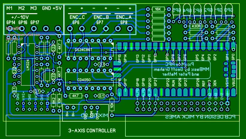 Mick Zilog Inside! nascom.info for Nascom & Gemini Preliminary MMBasic docs & my PCB designs |
||||
| Tinine Guru Joined: 30/03/2016 Location: United KingdomPosts: 1646 |
Slick and very quick, Mick  Only things I can't see (on my phone) are the enables for the 34C86 (?) Craig |
||||
| Volhout Guru Joined: 05/03/2018 Location: NetherlandsPosts: 3552 |
@Mick, I have some comments on the circuit. Please evaluate if these are important enough to change some things. 1/ The RECON 24V->+/-12V convertors do not have feedback inside. They have fixed transformer winding ratings. The +/-12V therefor are inaccurate with the 24V (26 unloaded, 22 loaded). Please check if you use -12V to create an offset for zero'ing the LM324. If so: a/ change the design to use a +/-15V convertor and add LM78L12 and LM79L12 to get stable +/-12V. b/ change the design to use the 3.3V to create an offset required for zero'ing. I can help you with that if needed. 2/ This board is dedicated for an application. You need 3 input channels per output. So with a single 34C86 you need only 1 PMW output = 1 sigle opamp (no need to layout a LM324 that is a quad pack). Worst case I would layout a dual (LM358) to convert 2 PWM to Analog, and connect the 4'th channel of the 34C86 also to the next PIO pin. When the index is not used, you could connect 2 encoders, and drive 2 motors. 3/ The smaller opamp package and removed R's and C's would allow for a better low pass filter (See my TL072 circuit earlier). If you layout that circuit, you could also place the components such that Tinine's classic circuit is used, but also add some components if more speed of resolution is needed. Edited 2022-06-07 16:52 by Volhout PicomiteVGA PETSCII ROBOTS |
||||
| Mixtel90 Guru Joined: 05/10/2019 Location: United KingdomPosts: 5735 |
Fixed that now. And a few grounds that weren't meant to be there. :) In fact, all the boards are on one file at the moment so testing is interesting as putting the probe on GND lights up the GND points on all of the boards via the ground plane. It's like a fireworks display. :) I don't know if you noticed, but the op amps share a common potential divider on the non-inverting input. It saves a lot of board space (another 4 resistors) but should be perfectly fine as the non-inv input of an op-amp is very high impedance. It does mean that the ratio is fixed for all three channels though (no bad thing IMHO), but that can probably be compensated for in software if needs be. The DC/DC converter can only supply about 33mA or 35mA. The LM324 draws approximately 3mA, so you can split that 3 ways for the outputs, allowing up to, say, 5mA for each to allow for as much output swing as possible. A short on a LM324 output can sink 40mA so the DC/DC converter will collapse. Would you mind asking Phoenix why they don't make an 11-way plug-in terminal block? Mick Zilog Inside! nascom.info for Nascom & Gemini Preliminary MMBasic docs & my PCB designs |
||||
| Mixtel90 Guru Joined: 05/10/2019 Location: United KingdomPosts: 5735 |
I'm totally confused now. (Doesn't take much) :) I thought there were three motors, each controlled by a PWM signal converted to +/-10V and each with an encoder feeding differential pulses back? In that case, surely you need completely independent control of all three motors - you need 3 op-amps... On the subject of the +/- supplies. Both will be the same (near as dammit) even if the voltage isn't accurate (which doesn't matter here). That has to be true as they are from windings on the same transformer. In any case, the output of the op-amp is on a closed feedback loop. If the PWM is set to 50% then the motor is stopped. if it isn't there will be feedback pulses and the output of the op-amp will be adjusted until it is. Imbalance in the supply rails would be cancelled out, wouldn't it? The intention would be to use +/-15V anyway to allow headroom for the LM324 outputs. My main problem with those DC/DC converters is that they will only accept up to 26.4V input, which I'm not happy about at all. I like to design "24V" stuff to withstand at least 32V continuously. I'd considered taking +15V from the 24V rail and using an isolated 15V converter to get the -15V. It's all board space though. Mick Zilog Inside! nascom.info for Nascom & Gemini Preliminary MMBasic docs & my PCB designs |
||||
| Volhout Guru Joined: 05/03/2018 Location: NetherlandsPosts: 3552 |
 The 15k resistor to 3.3V causes the offset to 0 at PWM 50%. The circuit outputs +/- 10.4V, but even at Vdd=3.2V you get +/-10V out. I would suggest to use a linear regulator for the 3.3V, just to make sure you have no jitter due to the noisy switcher on the pico. TL072 can also be a LM258 if so desired. Edited 2022-06-07 18:04 by Volhout PicomiteVGA PETSCII ROBOTS |
||||
| Tinine Guru Joined: 30/03/2016 Location: United KingdomPosts: 1646 |
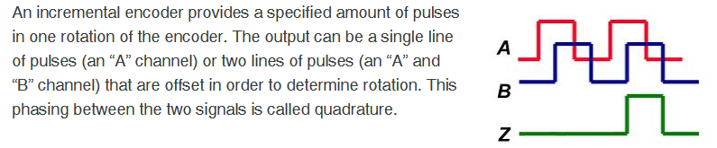
 No, this is single axis...I guess the encoder signals confused the issue. A single axis needs CHA and CHB for quadrature counting and CHC (aka: CHI or CHZ) for homing the axis. No, this is single axis...I guess the encoder signals confused the issue. A single axis needs CHA and CHB for quadrature counting and CHC (aka: CHI or CHZ) for homing the axis.A typical homing scenario: On power-up, the machine has no clue where the axis is because these are incremental encoders (merely pulse generators). There is typically a "home" sensor such as a proximity switch BUT these aren't considered to be consistent/repeatable enough. They are still needed because the encoder index pulse happens once/revolution and so we have to know when to look for it. If Home_sensor = low drive_axis_slowly_negative do:loop until Home_sensor = high stop_axis endif drive_axis_slowly_positive do:loop until Home_sensor = low do:loop until Index_pulse_transition stop_axis pre_load_or_zero_position_counter Craig |
||||
| Mixtel90 Guru Joined: 05/10/2019 Location: United KingdomPosts: 5735 |
Ah - right. I was just looking at your original info, actually, and realised this. :) I'll have another look at it, and at Volhout's filter which is very nice. :) Mick Zilog Inside! nascom.info for Nascom & Gemini Preliminary MMBasic docs & my PCB designs |
||||
| Volhout Guru Joined: 05/03/2018 Location: NetherlandsPosts: 3552 |
The above shown PWM filter in graphs:  The filter is designed for 10kHz PWM as earlier proposed by Craig. It has a group delay of 3.3ms...4.5ms, and this has to be taken into account when designing the Ki, Kp, and Kd parameters (in essence: after around 4ms the PWM value has transpired into 71% of the output value). As the filter response shows, there is NO overshoot. The pico can run 10kHz PWM at 13 bits (not 16 bits) as far as I know. That should be enough I hope. PicomiteVGA PETSCII ROBOTS |
||||
| Tinine Guru Joined: 30/03/2016 Location: United KingdomPosts: 1646 |
 |
||||
| Tinine Guru Joined: 30/03/2016 Location: United KingdomPosts: 1646 |
No problem 99.9%+ of industrial drives resolve to a 12bit motor command. Craig |
||||
| Mixtel90 Guru Joined: 05/10/2019 Location: United KingdomPosts: 5735 |
Second attempt: You can cancel the call about 11-pin terminal blocks now, Craig. :) Now using Volhout's filter and suggestions about the power supplies etc. All the boards now have terminal & LED markings on the back as terminal blocks and the LEDs themselves would cover them on the front. 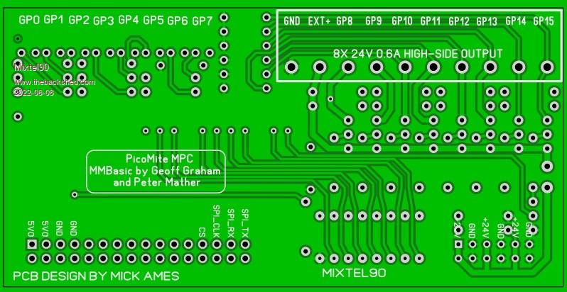 Mick Zilog Inside! nascom.info for Nascom & Gemini Preliminary MMBasic docs & my PCB designs |
||||
| Tinine Guru Joined: 30/03/2016 Location: United KingdomPosts: 1646 |
Looking good, Mick I'll put these 12-pin-ers away then 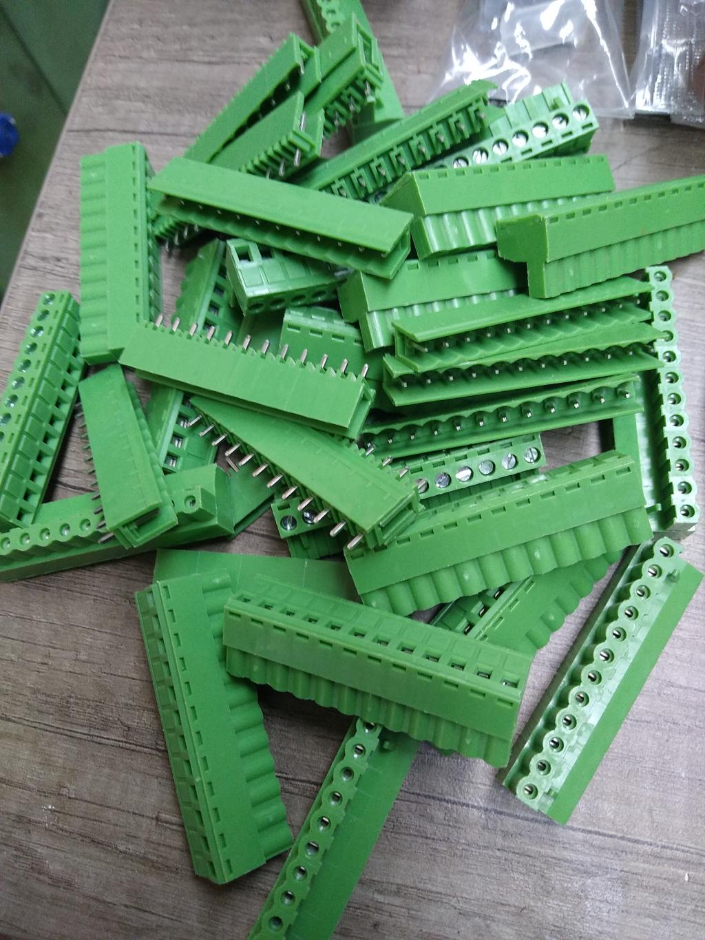 Craig |
||||
| Mixtel90 Guru Joined: 05/10/2019 Location: United KingdomPosts: 5735 |
Are those the 5.08mm centres or the 3.5mm or the 3.8mm ? I love standards. I've use 5.08mm ctrs, which are the chunky ones. I think they are 12A rated but that's totally unnecessary. I remember being able to do the screws up to a decent tightness. :) As the boards are relying on the 2-row headers for support the 3.5mm terminals might put less strain on them. Just a thought... I don't really want the hassle of card guides - and for small systems I think this is probably ok. Mick Zilog Inside! nascom.info for Nascom & Gemini Preliminary MMBasic docs & my PCB designs |
||||
| Tinine Guru Joined: 30/03/2016 Location: United KingdomPosts: 1646 |
Yeah 5.08mm for all connections. Not pushing any amperage at all, this is purely about beefiness. I won't be opening the panel doors, years from now, to find dismantled D-shells on the floor or a D-connector that has been half-melted by a soldering iron Craig |
||||
| Mixtel90 Guru Joined: 05/10/2019 Location: United KingdomPosts: 5735 |
Had a brainwave this morning and changed the bus to 4-wire+CS. That now allows the use of either SPI or COM2 with CS to each board and two interrupt lines. I had to do it this way as the SPI pins include COM2_TX but not COM2_RX. The extra line, being common to all boards, could well come in handy eventually as an o/c common back interrupt to the master when using SPI as the IO boards can't initiate SPI messages. What brought all this on was me wondering whether a true SPI slave could satisfactorily be run on a PicoMite. It's given me a useful fallback system for only a fairly minor hardware change. Each IO board would now have a board code. On initialisation the master would message all 9 slots and get the board code for each slot. This would then be compared with a list of boards and positions which would be part of the program. The master could then refuse to run if any boards were missing, in the wrong slots (and hence possibly wired incorrectly) or were non-functional. Mick Zilog Inside! nascom.info for Nascom & Gemini Preliminary MMBasic docs & my PCB designs |
||||
| Tinine Guru Joined: 30/03/2016 Location: United KingdomPosts: 1646 |
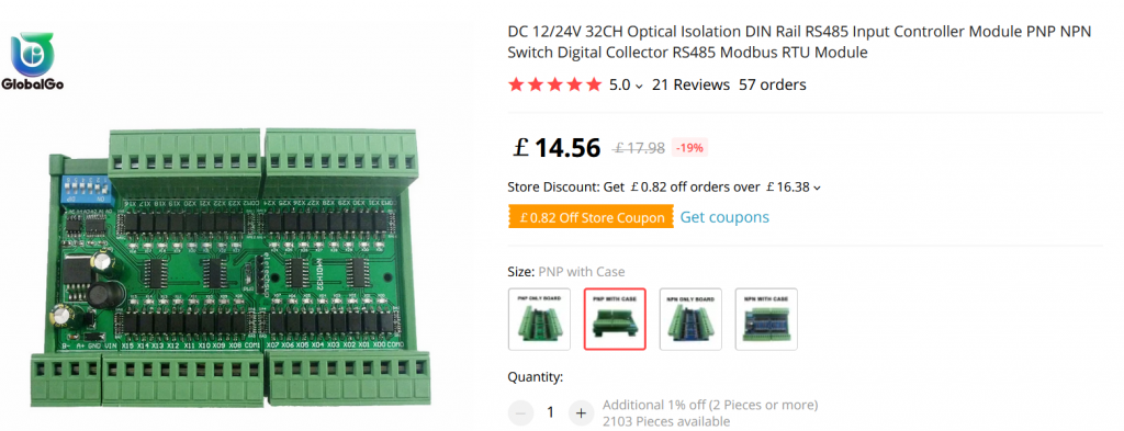
Was kinda thinking about this, last night. PLC! Kinda seems criminal that we have ModBus code, all ready-to-go. No idea regarding quality but Aliexpress has some nice-looking ModBus-compatible products.  Craig |
||||
| Tinine Guru Joined: 30/03/2016 Location: United KingdomPosts: 1646 |
 |
||||
| Mixtel90 Guru Joined: 05/10/2019 Location: United KingdomPosts: 5735 |
I already have a possible MODBUS over RS485 design - the SSD1963 converter. That's specifically designed for RS485 or I2C. (I really should get one built up. I got some boards but they are virtually useless as I got a lot of PTH holes too small to use. I've fixed the design but never got round to ordering more boards.) There's no reason why MODBUS couldn't be used on SPI either. I've not done it on this as I've used COM1 for the bluetooth module and now COM2 might get used for the MBC bus if I can't get SPI to work. The only possibility is to make another IO board with a serial interface on it. Because of the short distance involved on the base board I wasn't originally considering using MODBUS, but it's an idea as the PicoMite UART can run at over 1Mb/s. Mick Zilog Inside! nascom.info for Nascom & Gemini Preliminary MMBasic docs & my PCB designs |
||||
