
|
|
Forum Index : Electronics : Warpinverter Build
| Author | Message | ||||
| Alston Regular Member Joined: 04/04/2021 Location: AustraliaPosts: 63 |
I have still been working away on the inverter. With the assistance of Murphy's Friend I now have a choke to connect up to the big transformer. It's wound with recycled Aerosharp wire and the C cores epoxied together. Other than this I have built up the control board and tested it on a simulator board.  |
||||
| Alston Regular Member Joined: 04/04/2021 Location: AustraliaPosts: 63 |
I am glad others on this forum get distracted by other projects so I don't feel so bad when I take a break from the Warpinverter. I have got stuck back into and after tentatively powering up each section and do lots of testing I fired it up tonight with everything hooked up. I didn't have the caps fitted so it's a bit noisy but a great milestone for me. I am not in a rush to get it finished and am just trying to enjoy the build. 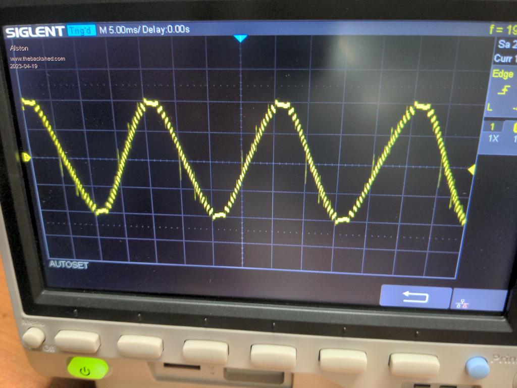 |
||||
| rogerdw Guru Joined: 22/10/2019 Location: AustraliaPosts: 797 |
That's looking good Alston, you're getting there. I hadn't noticed your post about the choke and am trying to work out where that fits in. Certainly looks solid and neat and tidy. I need a rocket up me to get back to work, though have been doing a bit here and there. Managed to strip another 3Kw Aerosharp toroid on the weekend to get enough wire for my medium transformer primary. Simply not enough hole size to use normal 25mm sqr wire. Cheers, Roger |
||||
| Alston Regular Member Joined: 04/04/2021 Location: AustraliaPosts: 63 |
Thanks Roger. The choke may or may not be needed, I have yet to actually test without it. If you have a look at this thread (24v inverter) https://www.thebackshed.com/forum/ViewTopic.php?TID=11481&P=2#136905 Mackofgrid discovered he was getting large spikes which fitting the choke solved. Klaus also has them fitted to his large and medium transformers. It can be hard to not get distracted with other projects when you are working on such a large project. Yours is a work of art and you will feel a great satisfaction when you power it on I am sure. |
||||
| rogerdw Guru Joined: 22/10/2019 Location: AustraliaPosts: 797 |
I do remember that now thanks Alston. I think Tony's suggestion was that we try and keep a gap between the core and the winding ... and then between the windings. I did put a 5 mm spacer all around the core ... but I won't have enough space for the primary if I add another after the secondary winding. Looks like I'll need to suck it and see. If I have spike issues, I'll yell out for more details. IIRC Klaus seemed doubtful that a gap would help solve it either. I can come up with lots of excuses for procrastinating ... but they are mostly pretty lousy excuses.  Cheers, Roger |
||||
| Murphy's friend Guru Joined: 04/10/2019 Location: AustraliaPosts: 583 |
The last thing you want to do when re winding toroidal cores is to waste hole space with gaps between windings. There are *no* gaps between the original Aeropsharp windings, just a very thin foil layer which may or may not help (I included that but it was a lot of work). Just make a decent choke, it's not rocket science with all the info shared on this forum supplying plenty of know how. Just make sure you have all the electronics powered up and running *before* you slowly charge the big capacitors which will thus soft start the inverter. I do *not* soft start mine with an AC load connected. |
||||
| Alston Regular Member Joined: 04/04/2021 Location: AustraliaPosts: 63 |
I am currently programming a microcontroller to handle the startup and shutdown procedures of my inverter. Hit start and it will auto pre-charge and so on. This will also handle temperature/fan control and over-current/under-voltage shutdown. I am just not sure what set points I should set. How hot should I expect the heatsink to get with a full 5Kw load and at what point should the fans kick in? I was also going to measure the temperature of the big transformer which I assume would take a really long time to heat up with that amount of copper, again what would be too hot? Something I haven't wired in yet are an AC line filters. Should I and have others recycled the ones from the Aerosharps? |
||||
| Murphy's friend Guru Joined: 04/10/2019 Location: AustraliaPosts: 583 |
Paul, I set my fan control (independent type) to come on at 55 degrees and turn off at 50 degrees at the heat sink. Only came on once or twice on a 40+ degree day in Summer and always cycled off. I do not have a steady 5KW load, perhaps half that, when the reverse cycle aicon is on. Re the AC line filters, they are rated for 3KW at most. The sealed box type is rated 7A so you need 3 in parallel (I use a single 20A rated one). I played with the larger alu box filter (has PCB on bottom), I think its under rated for 5KW. Tried it but saw no difference at the wave form. Remember, the warpverter has a different way to generate the sine wave, no 20KHz hash. |
||||
| Alston Regular Member Joined: 04/04/2021 Location: AustraliaPosts: 63 |
Thank you Klaus, just what I needed. I have recycled the LCD from the Aerosharp and got it hooked up to my microcontroller so will be using that to display info.  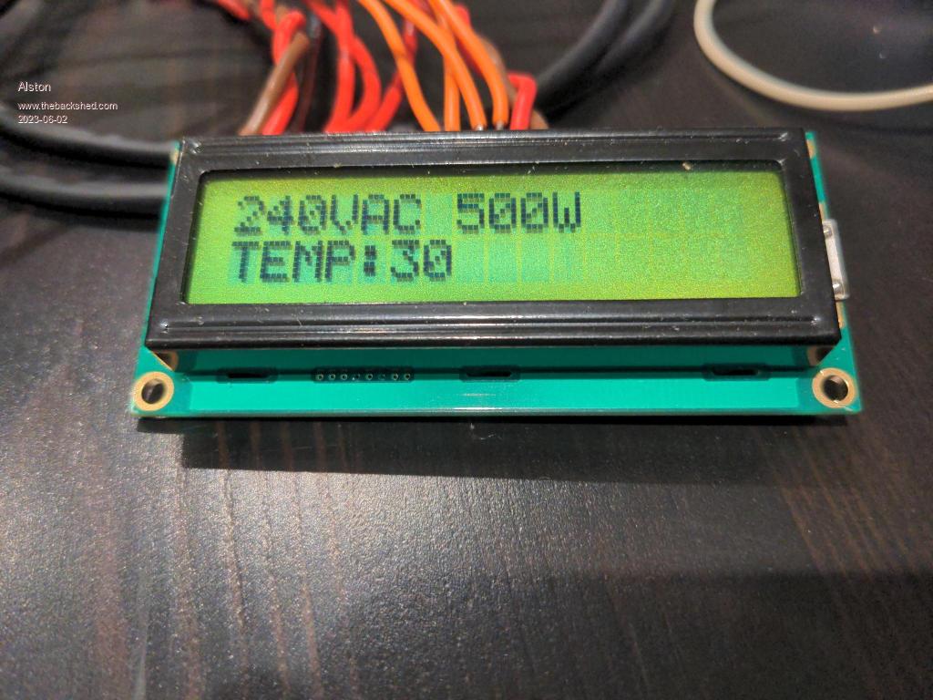 |
||||
| Alston Regular Member Joined: 04/04/2021 Location: AustraliaPosts: 63 |
Got most of the wiring done now, yet to test it with the capacitors in place as I had to get the pre charge side of things sorted first. The space above the Warpinverter PCB will have the control PCB. I have a pre charge relay with it's NC contacted wired to a discharge resistor so when that is shut off the caps will discharge. Tony mentioned ages ago he was having failures with his pre charge resistor due to thermal shock but after going with a very oversized one he hasn't had that, hence the large 200watt ones you can see in my photos. 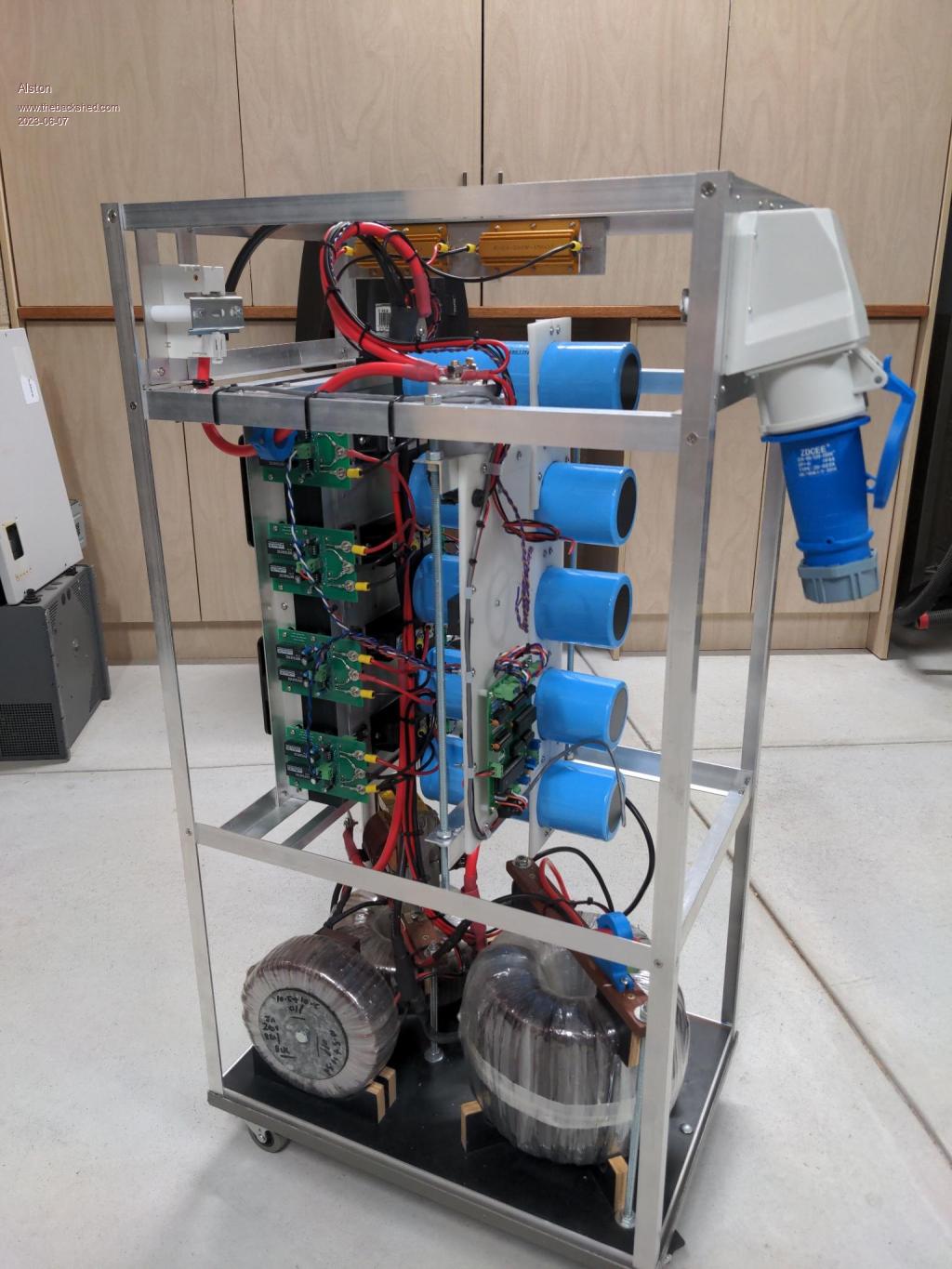 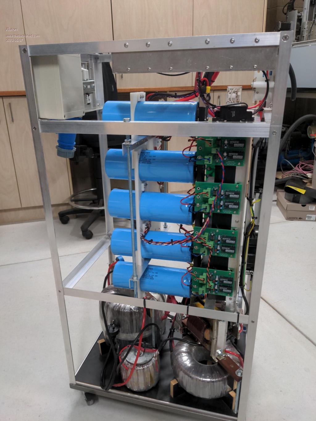 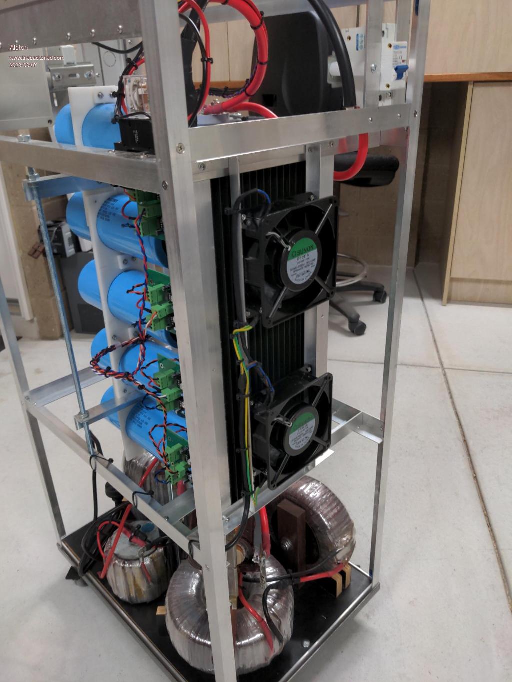 |
||||
| rogerdw Guru Joined: 22/10/2019 Location: AustraliaPosts: 797 |
Wow, that looks so good. I thought for a minute that you'd put new short caps in ... but then realised it was the spacer/holder that made it look like that. Viewing pix on mobile is pretty hard, will have to inspect again on the PC. What value resistance did you choose for the precharge and for the discharge resistors? Edit: Now I've had a closer look on my pc and am wondering what the small pcb is on the cap steady board (in the first photo)? I originally thought it was the control board but it looks different and you say you're going to fit that above. What size DC switch are you using? Edited 2023-06-08 09:26 by rogerdw Cheers, Roger |
||||
| Murphy's friend Guru Joined: 04/10/2019 Location: AustraliaPosts: 583 |
It looks like the control board I designed, I gave Paul a blank board. I did not like the tiny computer generated tracks on Tony's control PCB, on mine its possible to unsolder things without wrecking the pads  Nice job Paul, you are getting there. You might consider that test circuit I posted a while ago (it's a modified version of the board I gave you). It lets you power it up with the capacitors and see if the lights flash correctly at each of the 4 drivers & mosfets. After that is correct, it's only the transformer secondary phasing that needs sorting. |
||||
| Alston Regular Member Joined: 04/04/2021 Location: AustraliaPosts: 63 |
Yes that is Klaus's board which also included the hall effect sensor mod for output voltage control. I have had it running without the caps in place and have the transformer phasing all sorted. Hopefully I get some time this weekend for testing. I also need to take some measurements at the test points on your board Klaus and get that setup correctly. Roger the resistors are both 150ohms, mainly because I ordered a couple when I worked out my pre charging and that worked well for a good discharge value. Do you mean the DC breaker on the side or the contactor? I will have to check the breaker as I can't remember off the top of my head. The contactor is one of these Link Edited 2023-06-09 23:28 by Alston |
||||
| rogerdw Guru Joined: 22/10/2019 Location: AustraliaPosts: 797 |
Thanks for the explanation on the control board Alston. I have a large, perhaps 300 watt resistor but is only about 10 ohms. I scored it with some stuff recently. It's a good 8" long by nearly 2" diameter, but it looks the part? Still haven't decided if I'll use it.  Yeah it was the DC breaker on the side I was asking about. I suspected the solenoid was a Gigavac. Cheers, Roger |
||||
| analog8484 Regular Member Joined: 11/11/2021 Location: United StatesPosts: 89 |
Wow ... gotta love the massive capacitors. What is the inverter's target power capacity? |
||||
| Alston Regular Member Joined: 04/04/2021 Location: AustraliaPosts: 63 |
Roger it's a shame it's only 10ohms, that will be too low for both pre charge and discharge. I have 165000uF of capacitance so with 150ohms it can discharge to 10v in around 40 seconds. With 10ohms that that would be have to dissipate about 230 watts initially and take a couple of seconds to discharge. Analog8484 it's 5kw continuous |
||||
| rogerdw Guru Joined: 22/10/2019 Location: AustraliaPosts: 797 |
Yeah, and now I realise I've got 6 x 47,000uf caps ... that's 282,000uF so maybe I'd better get a couple closer value to yours. They'll certainly fit in more easily, though I was liking the look of mine. I hadn't even thought about a discharge one but can see the value in having it. Cheers, Roger |
||||
| Alston Regular Member Joined: 04/04/2021 Location: AustraliaPosts: 63 |
Ignore me Roger, I didn't account for the load of the bridges and so couldn't get the caps to pre charge with them hanging off the bus bar. I fitted a 10ohm resistor and it fired up and soft started beautifully. So it needs much more current than I was thinking. I then tweaked the pot to get 235v at the output but I didn't get time tonight to hook up the CRO and see what the waveform looks like now the caps are in place and I still need to load test it. |
||||
| Alston Regular Member Joined: 04/04/2021 Location: AustraliaPosts: 63 |
So the inverter draws 23.5w idling, happy with that result! I was looking at the output and with no line filtering and the waveform has various spikes and after fitting one of the Aerosharp line filters it's much better. Klaus did you just fit 3 of these to yours or buy a more suitably sized filter? Before line filter 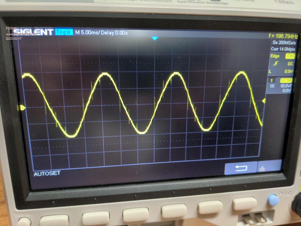 After line filter 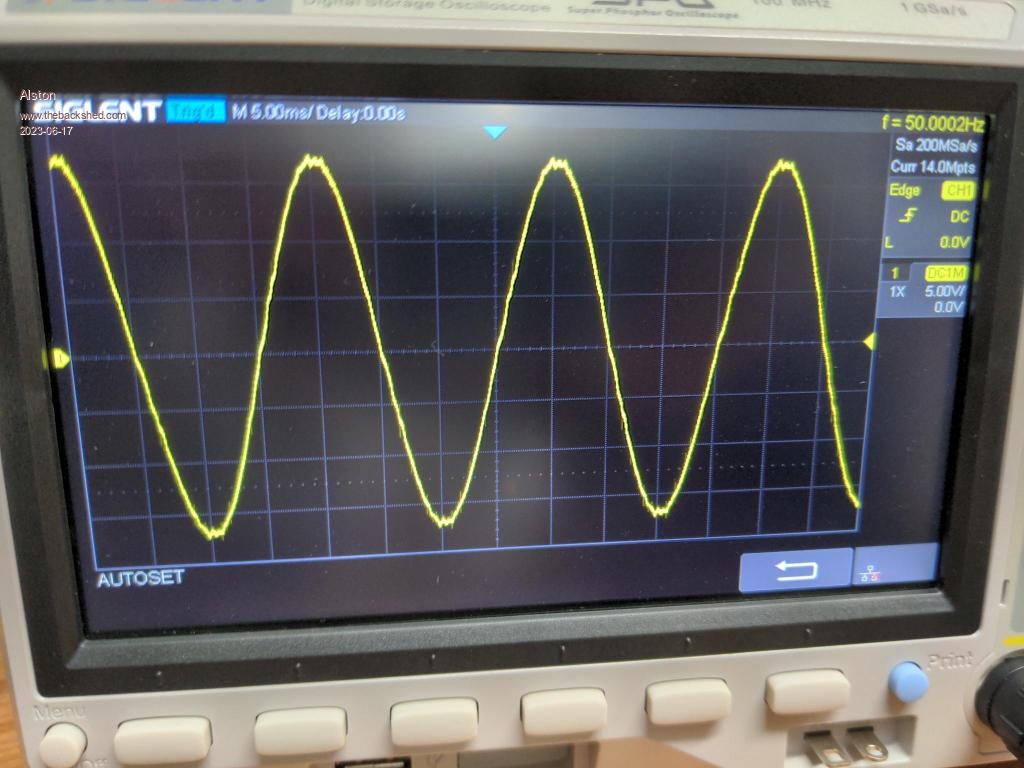 |
||||
| Murphy's friend Guru Joined: 04/10/2019 Location: AustraliaPosts: 583 |
|
||||
