
|
|
Forum Index : Microcontroller and PC projects : PicoMite VGA
| Page 1 of 2 |
|||||
| Author | Message | ||||
OA47 Guru Joined: 11/04/2012 Location: AustraliaPosts: 911 |
Am I interpreting this from the manual correctly? I have used SetPin 5,DOUT,OC and Pin(5)=0 when I measure the pin with the meter I get roughly 0V and continuity to GND, but when I use Pin(5)=1, I read 3.3V on the meter and get continuity to 3.3V. I interpret the above quote as I should not get continuity to high. I want to toggle the pin either low or high impedance. OA47 Edited 2022-09-27 14:01 by OA47 |
||||
| Volhout Guru Joined: 05/03/2018 Location: NetherlandsPosts: 3558 |
HI OA47, Yes, you are doing the correct thing. SETPIN 5,DOUT,OC should put the pin in Open(Collector)Drain mode. I have just confirmed that your observation is correct. I am using MMBasic version 5.07.05.09. I verified, it is a hard pullup (30mA when shorted) so not a weak pullup that is still active in OC mode. I will try with the latest (RC3) to confirm this is correct. Regards, Volhout EDIT: I can confirm that with 5.07.05RC4 the problem also exists. I will add it to the bug list (I hope Peter forgives me, because over the last 4 weeks I have issued few bugs that where not really bugs). Edited 2022-09-27 17:45 by Volhout PicomiteVGA PETSCII ROBOTS |
||||
| matherp Guru Joined: 11/12/2012 Location: United KingdomPosts: 8592 |
The RP2040 chip does not support open collector. You will have to mimic is by swapping between input and output modes. The manual should be updated to remove the option |
||||
| Mixtel90 Guru Joined: 05/10/2019 Location: United KingdomPosts: 5736 |
The RC2040 book isn't clear about how to do open drain outputs. It looks like it's possible, but it's a combination of two or three register settings. I was expecting a simple register change but no such luck. If you only need a single pin there's a work-around, I think. SETPIN mypin, DOUT pin(mypin)=0 Now, to set pin low SETPIN mypin, DOUT or to set it high impedance SETPIN mypin, DIN EDIT Found this: Edited 2022-09-27 17:54 by Mixtel90 Mick Zilog Inside! nascom.info for Nascom & Gemini Preliminary MMBasic docs & my PCB designs |
||||
| phil99 Guru Joined: 11/02/2018 Location: AustraliaPosts: 1794 |
I can confirm that the OC option does not work. Even with a 1k5 resistor to ground the voltage only drops to 3.23V, that is active high. A hardware solution is to put a diode in series with the pin, cathode to the pin. If the pin is used for two way comms add a 100k across the diode. Such a high value may slow things down so some experimentation may be needed. Peter must have found a way around it for the PS/2 keyboard. Edited 2022-09-27 18:05 by phil99 |
||||
| Mixtel90 Guru Joined: 05/10/2019 Location: United KingdomPosts: 5736 |
I don't know this application, but the usual need for open collector is to pull a load down to ground. Note that even if the Pico can do open collector (actually open drain) then the voltage on the pin can't exceed 3.6V so it can't be used for level shifting to a higher voltage. When you look at it that way any load that needs to be pulled down is simply connected between 3V3 and the output pin - there's no need for an open drain output. Simply use PIN(mypin)=0 to turn the load on and PIN(mypin)=1 to turn it off again. Edited 2022-09-27 18:21 by Mixtel90 Mick Zilog Inside! nascom.info for Nascom & Gemini Preliminary MMBasic docs & my PCB designs |
||||
| Volhout Guru Joined: 05/03/2018 Location: NetherlandsPosts: 3558 |
@OA47 Looks like there is no support for OC. If you want to create your own OC pins, then the simplest way is to add a FET to that pin. A good example is in the level shifters that are used to convert 3.3V to 5V. The 5V side is open drain. The 3.3V side can connect to a push-pull IO. The circuits used for PS2 keyboard connector will do the task. Regards, Volhout PicomiteVGA PETSCII ROBOTS |
||||
| phil99 Guru Joined: 11/02/2018 Location: AustraliaPosts: 1794 |
The problem is that OC is usually used when more than one active device is connected to the line. You don't want one active high while another is low. Only the pullup resistor should take the line high. |
||||
| Volhout Guru Joined: 05/03/2018 Location: NetherlandsPosts: 3558 |
Correction: the diode inside the FET will still drive the 5V side high. Look at the release candidates thread. The solution is to replace 'init pin setpin x,dout,oc 'set high micromite pin(x)=1 'set pin low micromite pin(x)=0 With picomite code 'init pin setpin x,din 'set high picomite setpin x,din 'set pin low picomite setpin x,dout pin(x)=0 Edited 2022-09-27 18:50 by Volhout PicomiteVGA PETSCII ROBOTS |
||||
| Mixtel90 Guru Joined: 05/10/2019 Location: United KingdomPosts: 5736 |
Open drain must be electronically possible, at least on some pins, as otherwise I2C wouldn't work. :) The RP2040 book isn't helpful. I see that oc outputs are possible in Micro Python though, so there is probably a mechanism of some sort. However, that doesn't mean that it could be done in MMBasic without a serious amount of messing about. Edited 2022-09-27 19:29 by Mixtel90 Mick Zilog Inside! nascom.info for Nascom & Gemini Preliminary MMBasic docs & my PCB designs |
||||
| OA47 Guru Joined: 11/04/2012 Location: AustraliaPosts: 911 |
Thanks everyone for the replies, I thought I was doing something grey haired for a moment. I will change the code to use the work arounds. OA47 |
||||
| Volhout Guru Joined: 05/03/2018 Location: NetherlandsPosts: 3558 |
And PS2 keyboard..... Volhout PicomiteVGA PETSCII ROBOTS |
||||
| Volhout Guru Joined: 05/03/2018 Location: NetherlandsPosts: 3558 |
@OA47 If you require this pin only to be OC output (not bi-directional) then this could help you. 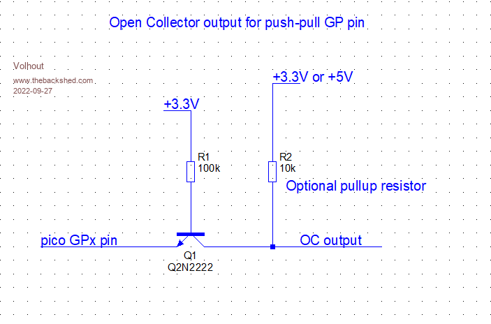 The transistor can be any small NPN. Regards, Volhout PicomiteVGA PETSCII ROBOTS |
||||
| phil99 Guru Joined: 11/02/2018 Location: AustraliaPosts: 1794 |
Just a schottky diode, cathode to pin, anode to pullup will do the same thing. If you need to switch between DOUT and DIN reduce the pullup to 2k2 and put a 22k across the diode. . Edited 2022-09-27 23:00 by phil99 |
||||
| OA47 Guru Joined: 11/04/2012 Location: AustraliaPosts: 911 |
What I was trying to achieve is an auto ranging resistor network to measure DC voltages on the Analog IN pin. I have used this circuit on the ARMites and MicroMites. 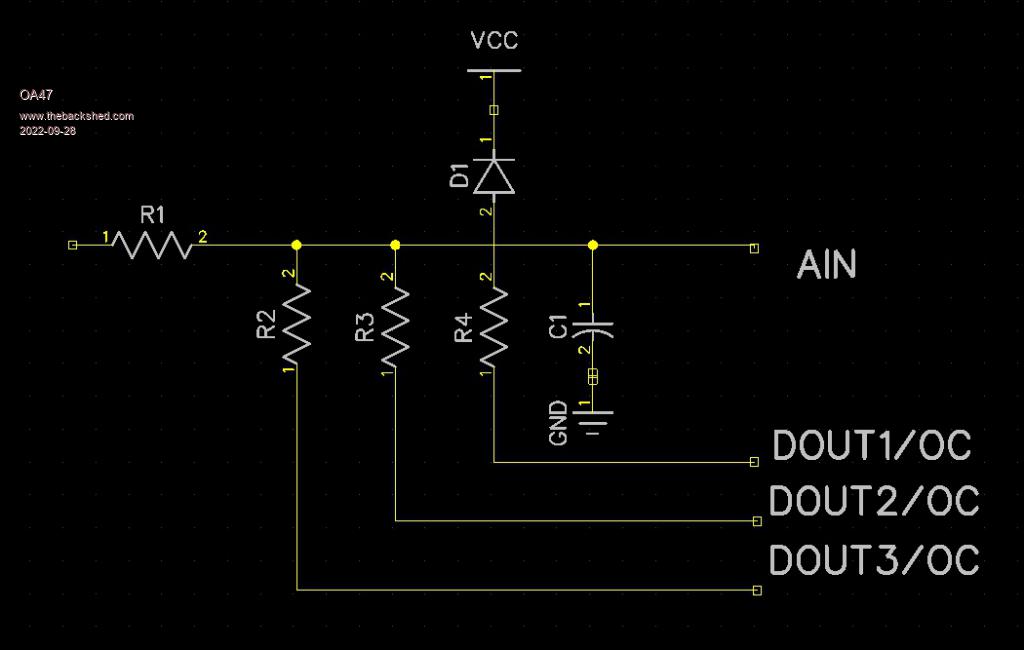 OA47 |
||||
| phil99 Guru Joined: 11/02/2018 Location: AustraliaPosts: 1794 |
Ok now we know what is needed. For accurate readings the resistors need to be pulled to ground with a low resistance. The Pico pins are about 50 ohms, so even if OC worked accuracy would be reduced. Use 2N7000 or similar MOSFETS to pull them to ground. Invert your DOUTs as a high will pull the resistor low. |
||||
| OA47 Guru Joined: 11/04/2012 Location: AustraliaPosts: 911 |
I am not worried by the 50 Ohm resistance of the Pico pin as I use the software to calibrate the readings 0-100V. Typically in the past I used R1=1M0, R2=1M0, R3=100K, R4=10K. OA47 |
||||
| Volhout Guru Joined: 05/03/2018 Location: NetherlandsPosts: 3558 |
Hi OA47. Your circuit will work (I have used similar many times before), there is however one thing you should pay attention to. The protection diode. For this diode to work, it should be a shottky diode. And these tend to have high leakage (1uA). If you put that against 1Mohm input impedance, you will see a non-linearity error (that is also temperature dependent). That is why real multimeters use different protection methods, i.e. with silicon diodes (or even si transistors used as a diode) that have leakage currents in the pA...nA range. Most microcontroller IO pins have very high impedance when in input mode, despite the fact that the datasheet may say different. Not sure about the pico IO pins, but microchip pins where exceptionally low leakage when tested for it. Regards, Volhout PicomiteVGA PETSCII ROBOTS |
||||
| Mixtel90 Guru Joined: 05/10/2019 Location: United KingdomPosts: 5736 |
Assuming you are powering the PicoMite from a 5V supply, one way might be to use a resistor and 3V9 zener (or, even better, a proper temperature-compensated shunt regulator like a LM334Z) to an "over voltage" point and use a conventional silicon diode with it's cathode to that rather than to VCC. That would give you protection above 3V3 with a lower leakage. Mick Zilog Inside! nascom.info for Nascom & Gemini Preliminary MMBasic docs & my PCB designs |
||||
| OA47 Guru Joined: 11/04/2012 Location: AustraliaPosts: 911 |
It seems even when I set the pin to DIN it puts out around 2.7v which is a similar problem to DOUT.  OA47 |
||||
| Page 1 of 2 |
|||||
