
|
|
Forum Index : Electronics : micro TIG
| Author | Message | ||||
oztules Guru Joined: 26/07/2007 Location: AustraliaPosts: 1686 |
candy bar... candy bar..... ok It seems you have gone out of your way to discover new and better ways to torture these things. Answer.... yes here we are at higher voltage. I rewound a larger transformer.. using 1.7mm wire on the primaries and secondaries. It easily goes over 60v, and at reasonable current (10 amps for short periods... havent got to cool the trannies down on the test bench yet) It is made from one of Spuds victims I was playing with. I had yet to see a 450W supply... so I took advantage of his. 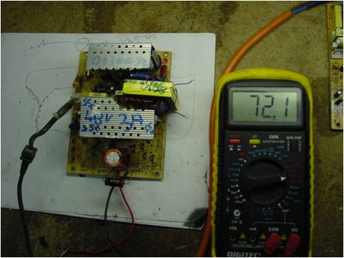
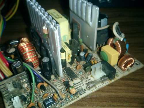
This was made easy by using an ATX supply. It gets it's Vcc from the little flyback tranny.... so is isolated from the output voltages anyway. You can see the oversize tranny here and the cool metalwork (gothic style), and the small loop to watch the switching waveform with the scope. 
Here is a different version for 48v battery charging/maintaining using the fullwave bridge as you are doing. 
In this guise (xt with full bridge), the 5v winding is still part of the 12v winding.... not an isolated winding.... So I figure that you need to use your earth end and the first tap for your power or even the center tap (Vcc<40v)).... if you used the two 5v tap points... then this is trouble??? did you do that perhaps forgetting they are the same winding not isolated. If you did do that..... you need a better brand of candy bar...... and I will get a giggle.... even though malnourished. ...........oztules Village idiot...or... just another hack out of his depth |
||||
| Dinges Senior Member Joined: 04/01/2008 Location: AlbaniaPosts: 510 |
Thanks for the speedy response. No, I didn't forget that the 5V winding is just a tap on the 12V one. What I did was basically rectify the 5V winding, add an inductor and a capacitor, then a 16V zener regulator. Full galvanic separation would've made life much easier. The TL494 is fed by 16Vdc w.r.t. to ground. I knew I was never going to get a completely isolated voltage for the TL494 - if only.... Yes, using an ATX PSU would've made life much easier for me in that respect. Alas, an AT is all I have now. BTW, I didn't rewind the transformer as you did, just disconnected the flying lead (this PSU had one) and built a full-bridge rectifier. Incidentally, I've seen voltage soar to over 80V.... Not good when the output elco is rated for only 63V. I attribute this to unhealthy (too low/noisy/choppy) voltage going to the TL494: my 16V zener-regulated voltage dropped to 8V when the PSU tried to start up. Will change the zener for a 10V/1W one and reduce the series resistor to 1k, and try again. I think it might just work, after all.... If I can't make it work without requiring an extra power supply for the TL494 I'll convert it back to its original configuration (2.5-29V, 8A out, nothing to be sneered at), and wait for a suitable ATX supply to turn up, to convert to 0-55V. Am currently out of PSUs: have thrown about 15 of them out in the latest move - will have to build my stock from scratch again. Those 450W PSUs you've got there look *very* tasty - never had anything above 300W myself so far. Will keep you posted on the developments. And from now on I'm not experimenting with PC PSUs without a series light-bulb - it saved my arse on about a dozen occasions by now. And yes, have learnt quite a bit about those PSUs in the past days - not to mention having practically memorized the TL494 datasheet by now. 
BTW: *very* impressive PSU projects you have there. You keep setting the bar higher and higher for me.... Peter. |
||||
| Dinges Senior Member Joined: 04/01/2008 Location: AlbaniaPosts: 510 |
As I was studying a generic schematic of a PC PSU (http://pavouk.org/hw/en_atxps.html) I suddenly realized the similarity to some simple DIY induction heater projects I've been studying recently (an induction heater is another project of which construction is planned for the near future). A very simple schematic of an induction heater (manually tuned): 
(taken from http://www.neon-john.com/Induction/heater.htm Basically *everything*, apart from the tank circuit (work coil and resonant capacitor) is already there.... just remove the output transformer of a PSU and connect the tank circuit of the above schematic? (C9,C10,L1,L2) Please say it isn't so.... but could the venerable PC PSU also be modified to a small (say, 300W max) induction heater? Modify the oscillator of the TL494 to make it manually tunable to the resonant frequency of the (loaded) tank, whilst running at limited power (DTC/pin4 high).... then, when it's tuned, crank up power (by lowering the voltage on DTC) for heating? Could it be *that* simple? Will this madness never end ?! Peter. (<-- wishing he never embarked on messing with those time sinks more commonly known as PC PSUs) Edit: after a quick google, it turns out Sam Goldwasser has already done exactly this: http://www.repairfaq.org/sam/lasercon.htm#consrp |
||||
| Dinges Senior Member Joined: 04/01/2008 Location: AlbaniaPosts: 510 |
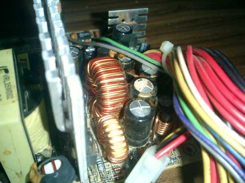
Ok - didn't succeed in properly powering the TL494 from the output transformer, so removed the full-bridge rectifier and assorted other parts. Will wait till an ATX supply turns up and modify that to 5-55V. After playing with another PSU, I noticed that the single-turn pickup loop I added around the transformer produced about 10Vpk-pk unloaded.... and could light a small lightbulb (6.3V/100mA) from it. So maybe I simply should have added two loops around the transformer, rectified it and fed the TL494 with it? Might have been a lot easier than what I was trying to do in the first place. Anyway, scoping the single-turn pickup loop was a real eye-opener. Amazing how dirty the signal is without load (or in my case, the 13W load the resistors put on the PSU to stabilize it; even with just 13W load the signal looks dirty, but at least the PSU makes no nasty sounds, as it did without any load). Adding a 24V/65W headlight as load immediately turns the signal in a very clean PWM squarewave. Reminds me of the experiments Oztules did with one of Spudd's PSUs. What a difference a load makes. On to the next powersupply - by now completely butchered up, with no longer even its output transformer present any more: 
After removing again the full bridge I had built and other added components, I also removed the output transformer and added a toroid with about 13 turns of wire for an experiment with the PSU as an induction heater. One leg of the large coil will be the single-turn secondary of the toroid transformer. With about 6.6uF worth of capacitors, the 0.57uH coil should resonate at about 82kHz; the switchmode PSU now works at 75kHz, so should be close enough. Will replace the oscillator resistor by a potmeter for tuning the circuit to the (loaded) tank resonant frequency. Then slowly crank up the power (either with a variac, or by lowering the voltage on the DTC pin) and see what happens. Anyway, will add a series lightbulb to the 230Vac, just in case... But who knows, it may just work as a crude, small (300W) induction heater. If it does work - I will be impressed with those power supplies even more. And to think they get tossed out by the thousands daily into landfills. Finally... I think it's about time to build a proper bench powersupply - with fancy meters and all. Have the perfect cabinet for it, with room for 3 PC PSUs. After a bit of thinking, I have decided to build two PC PSUs in it (one 1.2-29V, the other one a 5-55V one, when I find a suitable donor supply), and one switchmode PSU that puts out +5V @ many amps, +12V, +24V, -5V, and -12V. Will add a voltage and current meter on the front as well. Image below shows the cabinet it's all supposed to end up in: 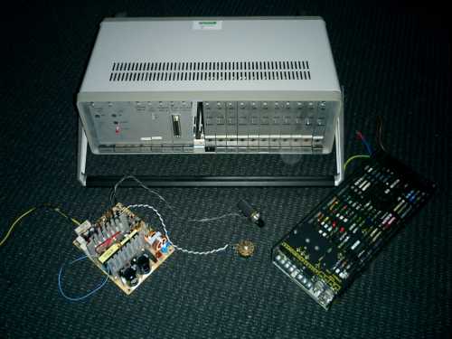
That should give me a very fancy powersupply with two current-limited variable voltage sources (1.2-29V @ 10A and 5-55V@ about 5A), plus the standard positive and negative fixed voltages. I think it will be a very useful addition to the laboratory. Peter. |
||||
| Dinges Senior Member Joined: 04/01/2008 Location: AlbaniaPosts: 510 |
After reading this story http://w5jgv.com/hv-ps1/index.htm I can't help but ponder rewinding a transformer from a PC PSU to provide 1500-2000V. Don't have any need for it, haven't played with valves in ages, but still - would be fun, wouldn't it? And useful too. Add potmeter for voltage control.... 
Or just rewind for 300 Vdc, isolated from mains. Would be very nice too for the experiments with valve audio amplifiers. Perhaps even add a little separate 6.3V winding with regulator for the filaments.... Peter. (<-- having so many ideas but no PSUs to try them out on) |
||||
| Dinges Senior Member Joined: 04/01/2008 Location: AlbaniaPosts: 510 |
Yes... it turns out you *can* use a PC powersupply as a small induction heater.... 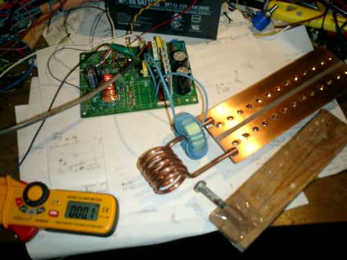
The test setup: a 200W PC PSU without fan, so I didn't dare to put in more power than 110W and even that warmed the tiny cooling fin more than I felt comfortable about. 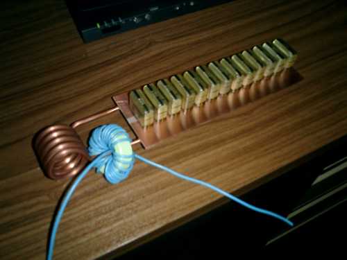
The work coil consists of 5 turns of copper brake pipe (5mm diameter), the capacitor bank consists of 13 pcs. 0.15uF/440Vac capacitors for a total of nearly 2uF. The resonant frequency of the tank circuit is 155 kHz, as determined by measuring and by experimenting. Replaced the timing resistor of the TL494 (which originally worked at 76kHz) by a 10-turn potmeter so I could increase oscillator frequency up to 400kHz and tune the PSU to the tank resonant frequency of 155 kHz (notice that the oscillator of the TL494 runs at twice the tank frequency, as it is running in push-pull configuration). The TL494 was powered independently from a 12V battery. Initially I ran the PSU with a series lightbulb and a variac. Slowly increased voltage as I scoped the tank circuit and monitored behaviour and temperatures of all components. Felt confident enough after a while to remove the series lightbulb and just use the variac - took it up till about 150V, but power increased only marginally (10W extra input) over 110-120Vac. Above about 150Vac oscillations stopped - I attribute this to saturation of the coupling transformer (powdered iron toroid, using it now for something it wasn't meant to do). There's not really room for more turns, but I'll try glueing two of them on top of eachother and rewind with the same number of turns. The material is probably MicroMetals type-52 (blue/green); at these frequencies it suffers from quite large losses, but it didn't become uncomfortably warm. A M8 bolt was, after about a minute, warm enough to start giving off smoke. After a few more minutes of heating it up I turned the machine off to feel if anything (besides the bolt) got warm - the cooling fins got pretty warm, and the lousy powdered-iron toroid (meant for RFI suppression) was warm too - but much less than I had initially feared. After a few minutes I touched the bolt - still hot. Turned out it was still warm enough to easily melt some PbSn solder, so at least 183C - I estimate it was over 200C. Not too bad, considering the very small RF output (estimated 60-70W) of the setup. After about an hour of experimenting one of the switching transistors gave up the ghost - not a surprize, considering how warm the tiny cooling fin had become in the meantime. The isolation pads probably didn't improve heat transfer as well. The increased frequency the supply was running at, 155 kHz vs. the original 38 kHz, probably also contributed to the overheating. Tank voltage was 10Vrms; turns out that retuning by adjusting the potmeter has hardly an effect, but it sometimes helps in starting oscillations by tuning the frequency of the TL494 around a bit. All in all, I'm very pleased with the results so far. It gives hope for further experiments with a more powerful induction heater - have started construction of a machine that is supposed to become a 2kW unit. But this PSU was my very first trial of induction heating and it didn't disappoint. All it took wa an old PC PSU, some copper tubing and a handful of capacitors. Peter. |
||||
| oztules Guru Joined: 26/07/2007 Location: AustraliaPosts: 1686 |
Are you using deadtime to control the output current? Neat idea. .........oztules Village idiot...or... just another hack out of his depth |
||||
| Dinges Senior Member Joined: 04/01/2008 Location: AlbaniaPosts: 510 |
No deadtime control (yet), but I was planning on trying that out on this PSU. Was still testing it with a variac when it went defect. And repairing the PSU seems to be a tad harder than I thought; I'll spare you the details. But repairing is the only option I have, unless I remove the PSU from the full-tower PC in the office for experiments.... 
Peter. |
||||
| Dinges Senior Member Joined: 04/01/2008 Location: AlbaniaPosts: 510 |
Isn't that just typical.... finally found another PC PSU (ATX) to play around with.... opened it....and was slightly stumped: they had forgotten to install one of the switcher transistors! And there was no TL494.... only a UC3845 in the high-voltage section and a WT7510 'power good/protection' IC in the low-voltage part. So probably the single power transistor is a feature, not an error  . .

Found the datasheets of both ICs. Not sure whether I'll try to convert it to 5-55V. Would much rather deal with a TL494, am familiar with those. Then again.... there once was a time when I wasn't familiar with TL494s either. If it hadn't been for Oztules' pestering, I'd still be unfamiliar with them. The PSU is functional at the moment, but the low-voltage electrolytics are bulging ominously. Peter. |
||||
| oztules Guru Joined: 26/07/2007 Location: AustraliaPosts: 1686 |
I just can't get excited about those flyback units. I like the halfbridge ones..... but the flies work well too. At least it will have current control for the switcher on the high side (look for a low value R in series with the fet). This should give you indestructibility before you start...... (chuckle chuckle).... well mostly anyway. .........oztules Village idiot...or... just another hack out of his depth |
||||
| Dinges Senior Member Joined: 04/01/2008 Location: AlbaniaPosts: 510 |
As I was at my favourite hardware store the other day (which also happens to have a welding machine repair dept. in-house) I tried my luck.... explained what I did (hobby electronics, needing parts (in my case, large ferrite cores) for a DIY induction heater) and that these were usually inside welding inverters. Asked if they were throwing an unrepairable machine away that I might gut for parts. 5 minutes later, Peter walked out a happy man.... with 4 large welding inverters under his arm. 
(also note the RF HV arcstarter in the middle/front left) 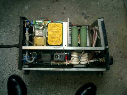
(another arcstarter in there too) 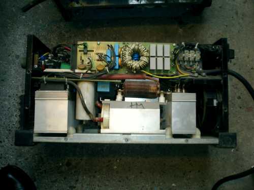
And I'm particularly happy with this cute little Kemppi MasterTIG 1500 inverter (230Vac, not three-phase 400Vac like the other machines): 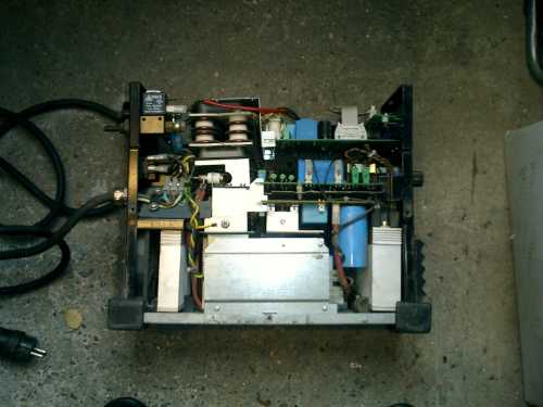

Had a bit of a chat with the guy who runs the repair department, which was interesting. As was to be expected, they don't repair at component level but simply replace modules. The loot: large 3-phase rectifiers (ISOTOP case), large cooling fins, big MOSFETs, big thyristors (SCRs), gate-drive transformers for same, a few huge caps, gas solenoids (another thing the doctor ordered for the microTIG), large rectifier diodes screwed into even larger heatsinks, etc.etc. There are also two RF-HV generators in there, with Tungsten spark gap... basically meaning my original experiments (using a ferrite rod and DIY HV generator and make-shift spark gap) were needless, as I've now got the professional thing right here in my hands, including the large ferrite cores to couple it into. I couldn't help but smile as I saw 1890s-technology (tungsten spark gap) in a machine from 1999, which otherwise consisted of fancy power semiconductors and a microprocessor to control it all.... Pity none of the cabinets are in a state to be re-used for a microTIG machine, but we'll worry about that part later. Those inverters are plain gold mines of parts. Peter. (<--Who can't resist but try to repair that cute Kemppi masterTIG 1500.... Don't have a 230V TIG machine in my collection yet, you see  ) ) |
||||
| oztules Guru Joined: 26/07/2007 Location: AustraliaPosts: 1686 |
Your just despicable! ...... and I'm jealous .. big time  Village idiot...or... just another hack out of his depth |
||||
| Dinges Senior Member Joined: 04/01/2008 Location: AlbaniaPosts: 510 |
Oztules, As I was walking away with them, I couldn't help but wonder.... "what would Oztules turn these into?". Then the thought scared me. Not sure why..... BTW: that sparkgap board takes about 24V AC square wave (not sure at what frequency, but is powered by the output from the inverter's main switching transformer, so about 20-30 kHz?) as input. Powering that RF HV generator looks to be a good job for a hacked PC PSU.... tapping directly into the transformer's secondary winding, before it gets rectified.... Is there anything those PSU can *not* be used for ?! Peter. (<-- wonders why, when you've got a hammer, every problem looks like a nail) |
||||
| Dinges Senior Member Joined: 04/01/2008 Location: AlbaniaPosts: 510 |
Came across this bit of information about modifying PC PSUs in another forum: "When you modify the feedback resistors in a SMPSU you are altering the set-point (i.e. the voltage that the control loop aims to keep the output regulated at) and also the loop gain (basically how drastically the control loop reacts to changes in the output voltage.) You should really change the reference voltage being fed into the Voltage Error-amplifier (and leave the feedback resistors alone.) This results in only the set-point changing, and no change to the loop gain. Therefore the regulation and stability of the PSU are not affected. I'm guessing that the SMPSU that you modded was to increase the output voltage only? It is possible to get reasonably acceptable results by decreasing the amount of feedback in an attempt to raise the output voltage from the supply. Decreasing the amount of feedback tricks the supply into thinking the output voltage is lower than it really is, and it increases the duty-ratio to compensate. The reason you can get away with this is that decreasing the feedback also decreases the loop gain. This acts to make the control loop more sluggish and more stable. So in summary, you can increase the output voltage slightly by decreasing the amount of voltage feedback to the error-amplifier, without much risk of instability. Trying to decrease the output voltage by increasing feedback is where the problems start. Increasing the feedback does initially trick the PSU into thinking the output is over-voltage and decreases its duty-ratio accordingly. However it also increases the loop gain and eventually the PSU will over-compensate for any disturbances at the output. The result is that it will usually break into oscillation before the output has reached half of the previous output voltage. This is because the control loop is normally designed with this 2:1 safety margin built in to allow for all of the component tolerances in the supply itself and the feedback path. If you didn't encounter any stability problems in modding your SMPSU, then i'm guessing you only tried to raise the output voltage, and didn't try to make it variable down to zero? The later is where you really do need to alter the reference to get any success" http://4hv.org/e107_plugins/forum/forum_viewtopic.php?61229 I have noticed the same thing occasionally with some of my modifications, where the PSU would squeal at certain settings (and indeed, always at lower voltages). This already suggested instability to me, but usually the squealing was nothing more than slightly annoying - I recall only one occasion where it may have caused the PSU to become defect. Next time will try to modify the voltage reference only (normally 2.5V fed back from the TL494's 5V reference) and see how that will affect things. From the rest of the discussion in that thread, I conclude that when you want to modify for higher voltages it would be fine to mess with the feedback resistors in the +12V, as increasing those resistors decreases loop gain. Something to keep in mind for the next PC PSU conversion, I think... And I think I'll modify the last PC PSU conversion a bit; I took it down to 1.25V, but that may be a bridge too far. 2.5V seems to be already pretty low... Peter. (edited for dumb error) |
||||
| oztules Guru Joined: 26/07/2007 Location: AustraliaPosts: 1686 |
I think we do that for the current amp? There the ref is changed by the variable resistor in the feedback leg.... so we change the gain and the ref all at once... by altering the "feedback" voltage.... which is so closely tied to ground as to change the ref voltage as well. I actually dont think of it like that, feedback to me is the pin3 stuff. I will try this angle out on the voltage comparator and see what results from it. I tend to not be going down in V, so haven't noticed any instability of note. It is a fair bet that it will have no effect on the trannies, as it will be at skinny pulse widths anyway.... but may effect the waveform some. It never ceases to amaze me what you can do to these things and they still work.... and conversely, how sometimes getting them stable is a problem. ..........oztules Village idiot...or... just another hack out of his depth |
||||
| Dinges Senior Member Joined: 04/01/2008 Location: AlbaniaPosts: 510 |
[quote=Oztules]I actually dont think of it like that, feedback to me is the pin3 stuff. [/quote] Gain of an opamp circuit is determined not only by the resistor between the output and inverting input, but also by the value of the resistor from the inverting input to the input signal; Ri is just as important as Rf.... 
The only PSU that really blew (and I think it was due to instability) was one I had modified for Ron and was ready for shipment. As I quickly needed a PSU for an experiment, I grabbed his - connected it up, adjusted the voltage, *poof*. This was a PSU that had a tendency to squeal. But on 2nd thought, I think I can think of another one that failed because of instability.... All my modifications have been made to include voltage adjustability both up and down, i.e. maximum range - 2.5...28V being common. The last conversion I took it down a step further to 1.25V by modifying the reference voltage circuit dividing resistors. And yes, some PSUs were a breeze to convert and get stable, and others were a nightmare. The very first PSU was a nightmare, but the 2nd one was a schoolbook case of converting. Curious as to your results on modifying the reference voltage circuit - I still don't have a decent PC PSU to play with (2nd one I found was *also* a flyback unit... Compaq :-( ; well.... there *is* that Mitra 48V/1500W PSU I'm meaning to gut and drive by a TL494... but that's a project for later) Peter. --------- Edit: The more I think about this (in)stability, the more I see that it was a problem in more PSUs than I thought. For example, the latest one I modified wouldn't react properly to the voltage control potmeter; that is, it would respond properly when I turned voltage up, but wouldn't respond properly when I turned it down from maximum. I.e. adjusting from 28V to, say, 20V wouldn't work - voltage would stay at 28V. It wasn't until I turned the potmeter nearly fully down that voltage dropped (very suddenly) to its set value, usually about 3-4V. I solved that problem by adding a lot of load - about 10 to 15W worth of load (at 28V) (the 3 power resistors can (barely) be seen in the picture at the bottom of page 2 of this thread). And even then, when I turned the potmeter down *very* rapidly, it would still not respond until a very low set point was reached. In practice, no one would so rapidly turn the voltage down though, but I still didn't like that behaviour. I 'solved' that one by installing a 10-turn potmeter instead of the original single-turn one - impossible to quickly dial down a 10-turn potmeter quick enough to cause the PSU to go unstable  . Hey, I never claimed to be sophistacated! In the end, I would have installed a multiturn potmeter anyway for more accurately setting the output voltage; I was just using the single-turn potmeter during the modification process. . Hey, I never claimed to be sophistacated! In the end, I would have installed a multiturn potmeter anyway for more accurately setting the output voltage; I was just using the single-turn potmeter during the modification process.
Apart from the instability issue... modifying a PSU for variable voltage using the voltage reference resistors seems to be a bit easier and quicker too.... simpler to find those resistors (connected from voltage reference pin 14 to the inverting input of the voltage opamp (pin 2) and ground) than hunting down the +12/+5V resistors.... though you don't need to be a Sherlock Holmes for that either. Peter. (<-- still a bit careful about his remarks - he remembers the last time he had a bright idea about those PSUs, by placing the current sense resistor in an 'innovative' location.... see earlier posts in thread.) |
||||
| Janne Senior Member Joined: 20/06/2008 Location: FinlandPosts: 121 |
Interesting points regarding the imput impedance to the error amplifiers. It might make some sense, because i also remember in one of my earliler experiments i had trouble getting to low voltages, without the psu starting to squeal. One way to test this would be to take a working psu, and, if it's configured like on the link below, replace the 27k R18 say with a 100k trimpot, and start turning it up while looking into results. http://www.pavouk.org/hw/en_atxps.html If at first you don't succeed, try again. My projects |
||||
| Dinges Senior Member Joined: 04/01/2008 Location: AlbaniaPosts: 510 |
Just had a chance to have a quick look at that Kemppi welding machine. Had already taken out the control boards and tested all the electrolytics and power supply voltages - all were fine. Wound a single-turn test winding over the gate-drive transformer for the IGBT to connect a scope to; re-installed the board and turned the machine on. 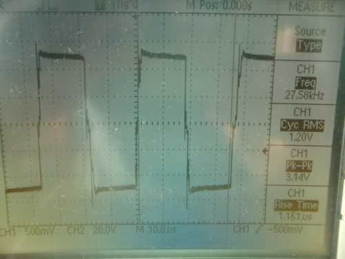
Perfect pulses on the scope, so it appears the IGBT is getting a drive signal. That rules out just about all of the control electronics as possible fault factors (note pulse is maximum width, but that's to be expected as no output current flows, so no current feedback to close the loop and regulate pulse width back to the set value) Then I tried to figure out where the various power components were. But before doing so, just to be sure, decided to short the outputs of the transistor with a large screwdriver (= shorting the electrolytic caps). Shorting the caps gave major sparks.... So looks like DC input is there as well. That seems to strongly indicate a defect IGBT block. Trouble is, to get at it (or any other part), the machine needs to be taken nearly completely apart (the downside of a small, compact machine....). And very hard to test-run it when taken apart. But everything so far seems to strongly indicate a defect IGBT brick, which means it's probably a simple repair. Funny though - it's basically an overgrown PC PSU, at 1500W. Half-bridge design, using two large IGBTs (in one brick). 2 electrolytic capacitors, the usual series capacitors to the transformer, and 2 flywheel diodes (will have to check those too). If the control board would've been dead and unrepairable, I think I'd have replaced it with a TL494 hack. May take a while before I get some more time & chance to have a closer look at it. Peter. Edit: turns out they're IGBTs, not thyristors. Was already scratching my head, wondering how thyristors could work in a half-bridge.... IGBT brick is defect - tested it and doesn't respond to a signal on its gates. Will have to wait with repair till I find a suitable replacement - I don't even want to know how much a Toshiba MG75J2YS50 costs.... bet you could buy a new Chinese welding inverter for the price. Got very lucky too.... one of the 3 electrolytic buffer caps (all parallel) makes a bad contact, dry solder joint. I had already discharged the caps (I thought....), but when I wanted to do a diodetest on the caps, huge sparks flew around. Turned out the one electrolytic cap, that had a dry joint, wasn't quite discharged. DMM is still fine, its owner was shaken though. The probe point of one of the DMM leads is completely gone - vaporized. 
I wouldn't have hesitated to probe around with my finger in that board, as I was convinced all caps were discharged.
|
||||
| oztules Guru Joined: 26/07/2007 Location: AustraliaPosts: 1686 |
I just noticed a consumer seller over here had 2000W induction cookers (domestic kitchen) for around $70. I wonder what is inside them.... and when they will turn up at the tip. ............oztules Village idiot...or... just another hack out of his depth |
||||
| Dinges Senior Member Joined: 04/01/2008 Location: AlbaniaPosts: 510 |
These two links give a glimpse of the innards of induction cookers: http://www.neon-john.net/Induction/Range.htm http://en.wikipedia.org/wiki/Induction_cooker Peter. |
||||
