
|
|
Forum Index : Windmills : Windmills for hot water
| Author | Message | ||||
Saaremaa Newbie Joined: 10/12/2005 Location: AustraliaPosts: 13 |
This seems to be a clever way to heat water. While not trying to discourage further development of this idea , I'm looking for potential problems first - and have come up with three. The first is aluminium is a very soft material. I'm not sure of the expansion coefficients of steel and aluminium. If very tight clearances are used and steel expands with heat more than aluminium does - then it may be just enough for any magnets mounted on the steel shaft to start gouging the aluminium. If the water which is being heated is unfiltered dam water then it would be conceivable that fine sand and quartz particles would be churned up by the action of the spinning shaft and possibly get caught between the aluminium and steel. Over time ,this would wear away the aluminim surface and decrease efficiency of the unit. The third problem is that with increased heat - the strength of neo magnets is decreased. I'm not sure if that is a permanent effect or not but I seem to remember reading that this effect occurred at a relatively low temperature , i.e. lower than 100C. Can anyone enlighten us on these points? |
||||
| Gizmo Admin Group Joined: 05/06/2004 Location: AustraliaPosts: 5012 |
Hey Bryan, I think your first magnet layout was better. Heat is generated whenever there is a change from N to S, so the more changes per revolution the better. Hey Saaremaa, the magnets and shaft are isolated from the water, the aluminium tube is sealed at one end. Water is only on the outside of the tube. The other points you made are worth noteing. Glenn The best time to plant a tree was twenty years ago, the second best time is right now. JAQ |
||||
| RossW Guru Joined: 25/02/2006 Location: AustraliaPosts: 495 |
neodymium CR2 (room temperature) (alpha, amorphous) 7.6 CR2 (room temperature) (alpha, crystalline) 13.5 CR2 (room temperature) (alpha, polycrystalline) 9.6 aluminium CR2 23.1 So, the aluminium tube should expand more than the magnets, thus the clearance will increase, not decrease. |
||||
| KiwiJohn Guru Joined: 01/12/2005 Location: New ZealandPosts: 691 |
Hi Gizmo, you may be right regarding the orientation of the magnets however I feel that as a general principle the best way to mount the magnets is the way in which there is the most repulsion between adjacent magnets (whatever that may be). My thinking is that the more repulsion there is the more the lines of flux are being forced away from the magnet assembly to look for an alternative path which hopefully will be through the aluminium. |
||||
| KiwiJohn Guru Joined: 01/12/2005 Location: New ZealandPosts: 691 |
Bryan, please see my comments to Gizmo regarding orientation of the magnets. Now the thought has struck me that having magnets on the outside of the aluminium may be more efficient, that is some magnets rotating with the shaft and some fixed and stationery. The flux lines would then be quickly re organising as the poles came into and passed alignment. This rapid changing of flux path is I understand what leads to the induction and subsequent eddy currents that produce the heat. |
||||
Megawatt Man Senior Member Joined: 03/05/2006 Location: AustraliaPosts: 119 |
Whoa gentlemen! The process of induction heating is one that is very dependent upon the rate of change of magnetic flux and the strength of the magnetic flux (read field for flux). The mill won't spin the magnets very quickly, so you won't create large induced voltages, hence eddy currents. Think about induction cooktops, they run at the power system frequency, 50 or 60 Hz. They induce into iron pots. Using iron means that the field really wants to enter the metal being heated, so magnetic field leakage is not such a big problem. Think about induction furnaces. For non-magnetic metals, they use very high frequencies, because they cannot achieve high field strength in the non magnetic material, so they compensate by having very fast field strength changes. But for heating iron, 50 Hz is plenty. Your heating element then, needs to be made of iron. There's a rust problem of course, so there's another problem to be overcome. Don't immediately think of stainless steel, because if its of good quality, it is non-magnetic. Megawatt Man |
||||
| Megawatt Man Senior Member Joined: 03/05/2006 Location: AustraliaPosts: 119 |
A couple more thoughts. Use an iron cylinder inside a stailess steel pot. The difference in expansion won't be too much, so they'll stay together. Using iron means that the arrangement of magnets doesn't matter too much. With a small clearance, the magnetic field will readily penetrate the iron to get the best chance of induction heating. Megawatt Man |
||||
Bryan1 Guru Joined: 22/02/2006 Location: AustraliaPosts: 1204 |
Hiya Guy's, Today at work I worked out in autocad I could fit 8 magnets around the diameter and 18 rows. This would mean 144 magnets and from what Gizmo mentioned about the N-S creating the eddy I reckon the arrangement shown below would give the best results as there will be heaps of poles. Now as this whole assembly is bearing based it spins without any torque so I intend to run it with a small dc motor with variable speed to see what speed would give the best temp. I know this little project could be all in vain but nothing ventured nothing gained and the magnets only cost $15. Cheers Bryan 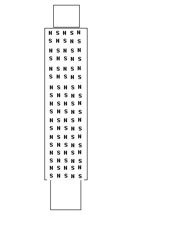 |
||||
makourain Senior Member Joined: 19/04/2006 Location: Posts: 111 |
why not just put the magnets on the outside? get a big round aluminium tube to put all ur water in, and have a whole bunch of speaker magnets to spin around the outside (speaker magnets coz they r cheap and easy to get) |
||||
| electrondady1 Senior Member Joined: 12/02/2009 Location: CanadaPosts: 208 |
well? what happened? did you build it? |
||||
MacGyver Guru Joined: 12/05/2009 Location: United StatesPosts: 1329 |
What a facinating idea. I've read the whole thread and nobody's mentioned the obvious method except the fellow who started the thread. He spun a ring of magnets in his lathe against a sheet of aluminum or copper and the metal got hot. Why not do the same thing with a 12-volt electric motor sitting down on the ground. Just manufacture a disk loaded with N-S-N etc. magnets in a ring and mount it on a mandrel that can be spun with a motor. This way, controlling the speed and duration of the motor would control the amount of heat created. Since most folks who build windmills create electricity, this would simply augment their efforts and become another way to utilize that resource. I'm back to pumping air with my windmill. An air motor would suffice in place of an electric one, so even in my case, it makes sense to use a motor to spin the magnets. I should think a VAWT free-wheeling and driving a ring of magnets against an aluminum tank mounted under the bearing plate would be a good way to heat water and utilize the wind. Of course, the water would have to be pumped, but in a closed system that's a no-brainer. I have a small solar pump that runs off 12-volt photo voltaic and it works just fine. It pumps water from my heater tank up to the roof many feet high and back again easily. RV water heater tanks are made of aluminum. I'd bet there is a way to use an unmodified tank with several magnet wheels spinning against its outside wall that would create several separate eddy currents and heat the water trapped inside. I will build one tomorrow and if it works (fat chance with my track record!) I'll post the build as well as the results here and maybe a video on Youtube. If this works, it opens up an entirely-new avenue of thought. Who knows what clever devices will evolve, especially from this crew! Edit: It's two days since I tossed this up and I just realized why I didn't see it before. The reason is, this thread is from the summer (USA) of 2006. Somebody asked what happened and it was brought to the top of the heap. That being said, I'm still intrigued and am building a test model, which when completed, will be posted on this thread. . . . . . Mac Nothing difficult is ever easy! Perhaps better stated in the words of Morgan Freeman, "Where there is no struggle, there is no progress!" Copeville, Texas |
||||
| MacGyver Guru Joined: 12/05/2009 Location: United StatesPosts: 1329 |
Crew I think I am beginning to see why this thread went dormant. The following picture shows what I did: 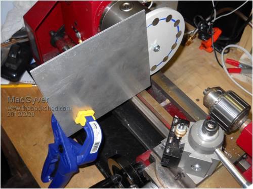
I turned a slab of HDPE plastic into a circle, divided it into 12ths and punched 12 holes equal distances apart from each other. I used a 1/2" "Forstner" bit to make sure the sides of each hole stayed 1/2" so I could shove the 1/2" x 1/4" N52 neodymium magnets into each one. The poles alternate N-S-N and so on all around the plate with 6 of each flavor. Next, so as not to contaminate the heat content of the aluminum plate with my body heat and fool myself into believing it works better than it does, I held it against the magnet wheel while spinning it in my little lathe, using a plactic Erwin quick grip and held the plate at 1mm away from the spinning magnets. I spun the headstock at about 580 rpm (based on an average HAWT shaft speed in heavy wind) for one minute, then touched the metal plate expecting to burn my fingers, but the fact of the matter is, although it DID get warm, it was only just barely warm. My conclusion is that although this works, it's not all that practical unless it were done on a much larger scale, but my hunch is larger magnets wouldn't produce any more heat perportionately. By that, I mean although larger magnets might creat larger eddy currents in the metal plate, the plate would also have to be bigger and it would take just as long to actually heat it to any temperature worth having as would a smaller one with a smaller heating application. I suppose I could create a dual magnet wheel and make this an axial-flux application, but at this stage of things, I'm thinking that might be a lot of wasted effort. If I were to recess the mandrel into the HDPE, so I could run the entire 12-magnet array up close and personal to the entire plate, my guess is it would work better by a factor of 2X or maybe even a little more, but unless someone else here chimes in and agrees, I'm going to leave this one alone for now. As far as using this in any practical application, like heating water as was discussed earlier in the thread, I don't see it happening. Too bad; it would have been a cool trick. Mind you, I had a good time building it, but my pile of fancy paper weights is ever growing! . . . . . Mac Nothing difficult is ever easy! Perhaps better stated in the words of Morgan Freeman, "Where there is no struggle, there is no progress!" Copeville, Texas |
||||
yahoo2 Guru Joined: 05/04/2011 Location: AustraliaPosts: 1166 |
Mac, megawatt man has stated it well. Aluminium does not resist the magnetic field so it penetrates right through and does not heat. you could make it work using a metal alloy with high ferromagnetic qualities coated in a heat tolerant plastic to prevent rust. However in time the plate would itself become magnetic and start to induce heating in the magnets and the machine would probably destroy the magnets. If I was having a go at it, I would find a large induction sauce pan or induction hotplate interface disc. some of them have the magnetic steel sandwiched between non ferrous metals to stop the rust. Induction heating is not hard to do, an old 240 volt single phase welder that has no rectifier diodes and a piece of thick copper rod that can be bent into a coil is all you really need. yahoo I'm confused, no wait... maybe I'm not... |
||||
| windtinker Newbie Joined: 16/01/2012 Location: New ZealandPosts: 38 |
Hi MacGyver You could try haveing a capactor and resistor in parrellel with the plate. Type of like n,s,n,s,n,s,n,s -----Plate--------- + + ---||--{--}-------- if the cap and res = 6 * 1 rev/sec 6hz tc = c*r it should resonate and heat up more |
||||
| Gizmo Admin Group Joined: 05/06/2004 Location: AustraliaPosts: 5012 |
Windtinker, I dont know if that would be easy to implement. Mac, I tend to disagree with Yahoo on this one ( sorry Yahoo ), in that I think aluminium will work. But it needs to be very close to the magnets, 1mm. Its should be fighting against the rotation of the magnet plate, so you will need to secure it well. Also, I would drill a hole in the middle of the aluminium plate to clear that bolt in the magnet plate, and mount it so its covering the whole magnet plate, and not just one side of it as in the photo. Lastly, run it for 10 minutes, that plate will act like a big heat sink and easily loose heat, so the longer the better. You should be able to notice it drawing power from the lathe, loading the motor, remember we need to put power in to get power out. I'll bet after 10 miniutes its a bit more than warm. The aluminium plate is acting like a big low resistance shorted out coil. A copper plate would work better, but copper is expensive. Imagine this thing as a axial flux alternator with the output shorted, it will get hot. I think you should keep experimenting with this one. Glenn The best time to plant a tree was twenty years ago, the second best time is right now. JAQ |
||||
| electrondady1 Senior Member Joined: 12/02/2009 Location: CanadaPosts: 208 |
mia culpa macgyver. it's an idea that keeps surfacing on lots of forums. i remember sometime back windstuff ed made a test rig that worked. i was just curious if byan1 had built one . one possibility i find intriguing, it turns the the rotation directly into heat. so at the base of a vertical mill i could build a heat source and air plenum. pump the warm air into my crawl space. that would help to keep my feet warm on cold and windy winter nights. |
||||
| yahoo2 Guru Joined: 05/04/2011 Location: AustraliaPosts: 1166 |
I remember borrowing a non-ferrous induction heater years ago, it was a power hungry brute! the instructions mentioned that it was adjustable from 120 Hz to 350 Hz. if I look at Macs magnets it looks like 12 magnets so that is 6 cycles per rotation that equals 1200 to 3500 rpm. I wouldn't spin my lathe that quick. I just thought that using magnetic resistance and eddy currents together with a ferrous metal plate at 6 to 50 Hz would give a far greater heating effect for less energy input than eddy current alone with aluminium. The only other comment I could make is that cold metal heats slower than hot with induction, I used to kick start it with a blow torch if I was heating a chunky object to get past the slow patch. You will get better results with a thinner metal plate. interested spectator  yahoo yahooI'm confused, no wait... maybe I'm not... |
||||
| MacGyver Guru Joined: 12/05/2009 Location: United StatesPosts: 1329 |
Glen & Yahoo2 Glen first: I had the metal square held @ 1mm away, but I didn't face the plastic disk, so it wobbles a bit. Maybe I should face it off tomorrow and try it again. Since you think there is some merit in this, I'll continue to mess with it. I'm still thinking a windmill freewheeling against the magnets will not create much heat, but I may be wrong. I have aluminum plate, but like you said, copper is way expensive. I wonder if brass would work. I have some brass sheet I use for fancy air engine models; I'll try it and get back here with the results. Yahoo2: The .125 aluminum sheet DID get warm and a thinner plate would have a lower thermal mass, so it would naturally get hotter faster, I guess. As for spinning the magnet disk at from 1200 to 3500 rpm, that's out of the question. The idea here was to use wind power to drive it. I've never seen a three-blade turbine run up over about 900 rpm even in a gale wind. I had one run awayand self-destruct in a 75 mph wind when I was stationed in Florida back in the 70s. I'm going to develop this using my lathe as a test bed and I'm going to run it no faster than 600 rpm. I'll clean up the magnet plate (face it square) and cut a hole in the center of the pick-up plate, then report the results here. When I was dinking around with it last evening, I did feel it trying to grab at the aluminum plate. That must be due to the current induced in the plate, then being attracted to the other magnets (I think). At any rate, I felt something tugging. I'm hoping to get this thing refined to the point of being able to use it to heat water directly from the shaft of either a "V" VAWT or a HAWT. I think I'll stick with the aluminum plate for now and if I can't git 'er done with that, I'll branch off to brass or copper or iron if I can find some with ceramic coating on each side. I was in hopes that I could drive the magnet plate with a small electric motor and create a source of heat for a small interior space. . . . . . Mac Nothing difficult is ever easy! Perhaps better stated in the words of Morgan Freeman, "Where there is no struggle, there is no progress!" Copeville, Texas |
||||
| Gizmo Admin Group Joined: 05/06/2004 Location: AustraliaPosts: 5012 |
Its hard to say how the thickness of the plate will affect the experiment. Unlike a ferris material that conducts the magnet flux lines, non ferris material like aluminium or copper is different and the flux lines should penetrate far into the material, almost as though it wasnt there. If you put a 3mm steel plate on those magnets, very little flux would be coming out the opposite side, barely enough to hold a nail. But I'll bet the aluminium sheet has little effect on the flux, and it will hold 100 nails. Therefore, a thicker plate should generate more heat, as it cuts through more flux lines. But... As soon as the magnets are moving, they are inducing current ( and heat ) in the aluminium plate. This current generates a magnetic field, flux lines, within the aluminium, that are working against the flux lines of the magnets. Thats why the plate feels like it is fighting against the rotating magnets, the magnet fields are pushing against eachother. This current and opposing flux may only be within the first few mm of the aluminium plate. So less flux from the magnets penetrates further into the aluminium sheet past this layer of electrical/magnetic activity. I also guess it depends on speed, the faster the magnets move, the less flux penetrates through the plate. So maybe thickness depends on speed. But I'm just guessing. Glenn The best time to plant a tree was twenty years ago, the second best time is right now. JAQ |
||||
| Greenbelt Guru Joined: 11/01/2009 Location: United StatesPosts: 566 |
KIWI JOHN, MacGyver,, Interesting project here! After reading a few Posts Its time to get involved. (1) The windmill pump Rod, as mentioned by Gismo, could be replaced with an auto differential ring gear or similar to drive a pinion down shaft to power a auto air conditioner compressor. One watt of Wind = three watts of heat. (2) Most of you on this Forum have Seen the Neo Magnet falling through a copper tube, this is the eddy current you seek. After watching this a few times, it appears that the Mag falls about one fifth the speed of a non magnetic object. It would seem that when the Mag is forced through at greater speed, it would have greater reluctance,and more Inductance. A crank with a long stroke to move magnets through the tube would give hi speed if driven by a down shaft off a ring gear/Pinion. The thickness of the metal appears to be a factor and the Copper Tube shows more reactance than aluminun as shown in one of the U-Tube Demo's. See this Link for a graphic description of the Mag and Tube. This link shows the Magnet falling through the Copper Tube. Mag and Tube Demo While Checking My links I found This!!! [URLWater Heater ]/URL] Just a thought while hiding and watching. .
------------Cheers, Roe Time has proven that I am blind to the Obvious, some of the above may be True? |
||||
