
|
|
Forum Index : Windmills : Anemometer building time
| Author | Message | ||||
KarlJ Guru Joined: 19/05/2008 Location: AustraliaPosts: 1178 |
i think this has been raised before as the wind energy is a cubic function it gets harder to turn with more rpm thus accuracy is lost with any kind of generator type anemometer but in reality i think close enough is good enough. ontop of that the wet finger method doesnt work in the rain and accuracy of that method isn't too hot either. I'm finding the Geezus rope is prooving to be a good anemometer, when its 60degrees out the back she's making 10A or better. still haven't seen anything like the 1KW i was hoping for  Luck favours the well prepared |
||||
Downwind Guru Joined: 09/09/2009 Location: AustraliaPosts: 2333 |
Gordon, Why do you choose 16 to divide the pulsin count by. Do it relate to the pulses pre rev you have. I would think 16 could be any figure, just curious why you choose 16. Pete. Ps. i think you mean 65335 and not 65535 as well??? Sometimes it just works |
||||
| Downwind Guru Joined: 09/09/2009 Location: AustraliaPosts: 2333 |
At a quick draft of a basic program i came up with this. 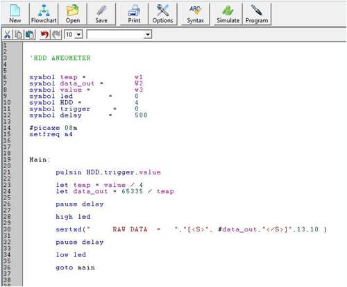
Its for a 08m picaxe. Any points of view....ITs only a first draft and just raw data out. Any conversion/calibration will be done in Piclog on the pc. Pete. Sometimes it just works |
||||
| GWatPE Senior Member Joined: 01/09/2006 Location: AustraliaPosts: 2127 |
Hi Pete, You need to get a number that fits the precision of the final reading you want. Remember that a picaxe can only perform integer maths. I wanted at least every 10RPM, at the lowest RPM, so 16 was the divisor. If I had chosen 128, then resolution would be compramized at the high rpm. 32 is probably the best, with 3 readings. This would give approx 1% across the RPM range. Hardly needed though. BTW 2^16-1 is 65535. Gordon. become more energy aware |
||||
| Downwind Guru Joined: 09/09/2009 Location: AustraliaPosts: 2333 |
Hi Gordon, BTW 2^16-1 is 65535..........Ok i was thinking a Word-register will only handle 0 to 65335 so thought you had worked to that. Pete. Sometimes it just works |
||||
| GWatPE Senior Member Joined: 01/09/2006 Location: AustraliaPosts: 2127 |
Hi Pete, I suppose you are referring to the text from the picaxe manual. I am afraid there is a mistake in the manual. I suppose this is a case of spell checking is not proof reading. This could be the extract. 
The number pointed to should be 65535 If you don't believe me then try this little program and run with the simulator main: w0=65534 w0=w0+1 w0=w0+1 w0=w0+1 goto main As you step through the program, make sure you select to display word variables. The register w0 will change from 65534 to 65535 to 0 and then to 1, as expected. This is normal integer maths. I hope this clears up why I used the 2^16-1. 1111111111111111 in binary. Gordon. become more energy aware |
||||
| Downwind Guru Joined: 09/09/2009 Location: AustraliaPosts: 2333 |
Hi Gordon, Correction noted. I had thought 65335 was weird but had not over flowed a word register to check. Its quite clear when you look at it in binary. Thanks. Pete. Sometimes it just works |
||||
kingw Newbie Joined: 07/03/2010 Location: United StatesPosts: 23 |
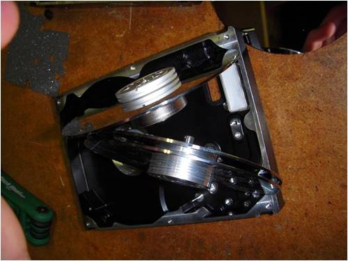
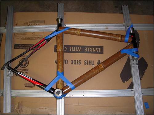
Been a busy weekend. Turned a carbon fiber bike into a bamboo bike, still working on it. I had company from out of town helping and took up my anemometer time. We are back on it full gas. I have access to a lot of HDD parts, a company next to my work does data recovery. When they can't recover, I can get parts. (big pictures...) http://thegyre.org/imgs/anemometer/4_hdd.JPG http://thegyre.org/imgs/anemometer/2level_vs1level.JPG http://thegyre.org/imgs/anemometer/motor__s.out.JPG I've left one completely intact in case I do anything terrible. Some have are double deckers, others just have one level. Also one has a bearing attached to a smaller post, and two others have fatter bearings sticking out of the bottom, I can take pictures. I am contemplating the best way to build a base for these. Maybe just route the bottom of the HDD housing in the shape I want? Suggestions? I think I'm going to make one with the cyclomter to compare to the photo interrupter, side by side. For now I'm starving, been working on the bike non-stop! (big pictures again) http://thegyre.org/imgs/bamboo_bike/main_tri.JPG http://thegyre.org/imgs/bamboo_bike/jig-cut.JPG http://thegyre.org/imgs/bamboo_bike/grinding.JPG http://thegyre.org/imgs/bamboo_bike/curin.JPG -kingw |
||||
| Downwind Guru Joined: 09/09/2009 Location: AustraliaPosts: 2333 |
We really need to teach you how to post a link using the link button above and also how to resize a photo and post it into the forum. Your photos are massive in file size and took me a month of Sundays to download to view, so i pitty the poor sods on rock ape dialup. Here is the photos KingW posted above. 
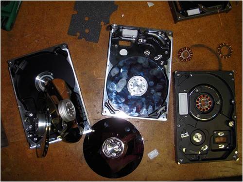
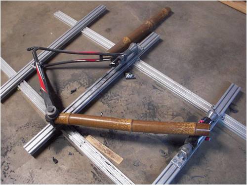

Pete. Sometimes it just works |
||||
| Downwind Guru Joined: 09/09/2009 Location: AustraliaPosts: 2333 |
Back to the aneometer.... any or all HDD will suit your purpose. There is little difference between each hdd except for the number of platters (discs) they have. The cogging effect (or drag) that the the magnet causes is a problem. I set up a rough test using the hdd motor for a pulse generator against the aneometer i built with no hdd magnet and just the photo interupter from a printer as a sensor. The aneometer using the photo interupter will spin if a fairy farted and will record down to 0.1 kph easily. The aneometer with the hdd motor as a signal generator needs above 6kph to start it turning and maybe not accurate till 10kph. If all you are interested in is recording the higher wind speed and nothing in low speed than the hdd motor makes for an easy project. To me it is a waste of time if the bottom end is not equally read to the top end of speed. I would recommend you strip out the inner windings and steel core and use some form of pulse detector like a photo interupter or hall effect sensor to reading the hdd motor magnet. This way it has no friction drag and makes use of the full advantage of the excellent bearings a hdd motor has. As Gordon has surgested the use of larger cups will help with the use of the hdd motor as a signal generator. But from my testing it would need cups the size of breakfast bowls to make it work and then this would cause problems with higher speed. Think it best to not use the hdd motor for a signal generator itself. The hdd motor i used, was like the one you have that has a pin/shaft pressed into the housing. I removed the pin and used a rod from the canon bj printer i ratted the photo interupter from, which happen to be 5mm dia the same as the pin in the hdd motor. This gave me a long shaft for easy mounting. If you can power the bike sensor with between 3-5v then we can use the same aneometer if you wish, to supply the picaxe with a pulse signal as well. As Ross and Gordon has pointed out, we can use a low pulse rate to high accuracy just as well as a high pulse rate. (Ross....im still kicking myself for not thinking of using interval timing...Doh!!) William you need to sort out how and with what you will generate a signal x-times per rev, so i can design a basic circuit to suit...and then it comes to software. Before i can give you a shopping list i need to know your thoughts on signal generation. As for a supplier of the picaxe chip, a lot of electronic outlets dont stock them, so you well might need to order them seperate and if so i would recommend this supplier, as i can buy from him including postage for 1/2 the price of what i can locally, and im in Australia and you are more local to him than me. PICAXE CHIPS HERE I would say get at least the 3 x 08M picaxe chips....you will find a use for them. Pete. Ps: With easter comming on its a good time to stock up on egg moulds for cups..........Its a once a year aneometer cup supply. Sometimes it just works |
||||
| kingw Newbie Joined: 07/03/2010 Location: United StatesPosts: 23 |
Sorry about the picture sizes Pete. End of a long weekend, and I had skipped taking the extra time to resize them. I did read on another thread how you post the pictures up smaller, I will find that again. Long weekend, lots of projects, dirty hands and hungry belly made me lazy ;p I will start sourcing a shaft, I should be able to find one without much trouble. For the signal generation it sounds like x amount of holes evenly spaced can be used to generate a signal, so long as we program the circuit with that figure in mind. If I remember right a rough circumference is around ~300 mm, I will get a more accurate measurement when I get home from work so that I can divide it as easily as possible by a few different numbers. I will get a picture/PN of my photo interrupter also. Lots to do, lots to do! Looking forward to riding my new rig, more pictures to come! -william -kingw |
||||
| Downwind Guru Joined: 09/09/2009 Location: AustraliaPosts: 2333 |
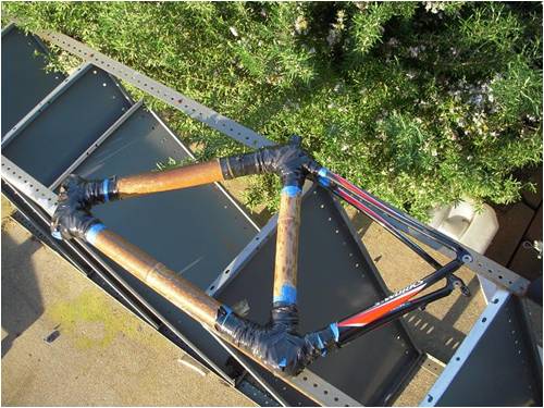
Looking at your bike ...for some reason Cheech and Chong comes to mind. Just dont get it wet as it might Grow. 
You will need to watch out for Panders as well. Do you intend to replace the cf back section to? Pete. Sometimes it just works |
||||
| kingw Newbie Joined: 07/03/2010 Location: United StatesPosts: 23 |
Oh boy, Cheech and Chong bike, if it catches fire gather round! I will probably sand the back cf section down and wrap it with hemp (there's your chong for you!) and epoxy. Keep it brandless that way. Played with anemometers tonight. I have two functional spinning platters that can be tinkered with. One i took and just made a basic conceptual (all tape etc..) anemometer just go through the motions and work out measuring kinks etc. Nothing on it is permanent so I can start the platter from scratch again. 
the other platter is much more clean so far as spindle is concerned. 
-kingw |
||||
| Downwind Guru Joined: 09/09/2009 Location: AustraliaPosts: 2333 |
Looks like you shop at the same aneometer spare parts store as me for your cups.
I found if you give the platter a rough up with some sandpaper you can solder onto them. Have you gutted the motor out yet? Pete. Sometimes it just works |
||||
| kingw Newbie Joined: 07/03/2010 Location: United StatesPosts: 23 |
Yes, gutted. The double platter spins just as you say, on a fairy fart. The plumbing mounted one spins freely, but not quite as nice. I am inclined to use the double platter for the real project. My photo interrupter does not fit between the platters though.. maybe I can find a smaller one, or have it go over the two platters. It is extremely reflective. I was thinking ruff it up and epoxy, however solder seems to be a quicker more permanent way to keep it aligned. -kingw |
||||
| Downwind Guru Joined: 09/09/2009 Location: AustraliaPosts: 2333 |
You may well find you can take the platters apart and change the spacings around as they are only held together with the washer on top. Pete. Sometimes it just works |
||||
| Plats Newbie Joined: 17/03/2010 Location: United StatesPosts: 1 |
A quick question, what is the sensor pickup? Is it just a reed relay that is tripped by a magnet? If so, then with a simple circuit, you could extend the wiring for miles. |
||||
| Downwind Guru Joined: 09/09/2009 Location: AustraliaPosts: 2333 |
The choice of sensor is one that the builder can decide. It could be photo interupter, Hall effect, motor windings, tape recorder head or as you say a reed switch, the only problem with a reed switch is if you want to use the internal magnet from the motor than it is very tight on mounting room and i doubt it will fit in. There is no reason you could not add a few magnets and do it external. All that is needed is a pulse stream of signals that can be squared up and fed into a picaxe for processing. Really it is a cheap project and is made from what one can scrounge or has lying around rather than well designed and thought out down to the last screw. Pete. Sometimes it just works |
||||
| kingw Newbie Joined: 07/03/2010 Location: United StatesPosts: 23 |
Pete's a pro. His scrounging will outdo my good effort! I'm making fair progress though, I've found my photo interrupter and I have drilled my pulse platter. I think 4 cups will be good based off suggestions because of cup sizes and wind dynamics. I've got a grinding guide that I'm going to glue onto the top platter to make a good surface to solder the spokes onto. All the picaxe stuff is in the mail and I'm getting ready to rock and roll. Thank you for all the help and discussion everyone, this is turning out to be a fun project. 
 -kingw |
||||
| KarlJ Guru Joined: 19/05/2008 Location: AustraliaPosts: 1178 |
nice work lads I paid a fortune for mine. APRSWORLD, data logging job. will do lots of other stuff as well but my tip is very simple. MUST be on the same mast as the turbine for any kind of accuracy, mine is a good 2.6m above the shed which is two stories high. it is just 80m from the turbine and yet depending on the wind direction i can see 200W at 2.5m/s or I can see nothing - 0 output. thus the old phrase useless as tits on a bull! put it where you intend to place the turbine regards Karl Luck favours the well prepared |
||||
