
|
|
Forum Index : Windmills : Ceiling fan motors as induction generator
| Author | Message | ||||
| Gizmo Admin Group Joined: 05/06/2004 Location: AustraliaPosts: 5012 |
I've read a few web sites about using induction motors as generators by connecting capacitors across the output. http://www.qsl.net/ns8o/Induction_Generator.html http://www.windpower.org/en/tour/wtrb/async.htm http://www.microhydropower.com/staffpubs/staff4.htm http://users.aber.ac.uk/iri/WIND/TECH/MISC/MotorsAsGenerator s.html The problem with these is they are usually 4 or 2 pole motors, and need to be spun at over 1500 or 3000 RPM before they start generating. They can be tricked into working at lower speeds with changes to the capacitor value. Now a ceiling fan has a much higher pole count, 8 or more, as its a slow turning induction motor. I wonder if it could be used as a low speed induction generator. It would need some smart electronics to... -Only apply load once up to speed. -adjust the capacitor value with RPM to maintain excitation. -disconnect load below a RPM to avoid demagnetising the rotor. - if the rotor is demagnetised, apply a brief pulse of power to the coils to magnetise the rotor. The advantage is any cheap ceiling fan could be used as a generator without buying magnets and machining the rotor down to glue them in place. Bascially you get a old fan motor and attach the electronics to make a generator. I dont know, what do you guys think? Glenn The best time to plant a tree was twenty years ago, the second best time is right now. JAQ |
||||
Megawatt Man Senior Member Joined: 03/05/2006 Location: AustraliaPosts: 119 |
I have written a post ot two on this subject before. The action of the capacitor is to act in part to complete a circuit and part as an energy store for the magnetic field needed to cause induction in the coils. The problem with it is that very high voltages develop, significantly higher than say 240V. It is an interesting thing. With the cap in circuit, when you start the machine spinning, residual magnetism cause a small current to flow and that causes a bit more magnetism and that cause a larger voltage and so on. The cap must be matched very carefully to the motor/generator, so the the capacitive VAR flow equals the inductive VAR flow. In fact the cap provides the magnetising current for the rotary machine. There's probably a bit of resonance happening here and very high voltages develop. As I have observed before, there are very many adventurous souls active on this site some of whom are game for almost anything. For those blokes, I say don't try this at home. Megawatt Man |
||||
WXYZ Newbie Joined: 30/04/2006 Location: CanadaPosts: 20 |
Here are some pics of a brushless rotor that was on a small gas powered genny. First the rotor and circuit board. 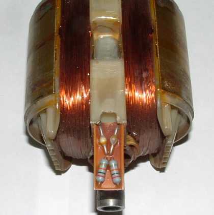
I also have a close-up of the circuit. There are two of them, one for each winding. 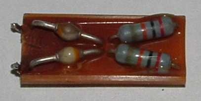
The last picture is the circuit diagram. 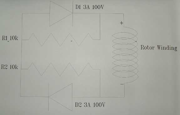
The rotor also has two exciter magnets sunk into the laminations 8mmx8mm. Joseph "Failure is an option." |
||||
