
|
|
Forum Index : Windmills : White Pointer AXFX
| Page 1 of 3 |
|||||
| Author | Message | ||||
Trev Guru Joined: 15/07/2006 Location: AustraliaPosts: 639 |
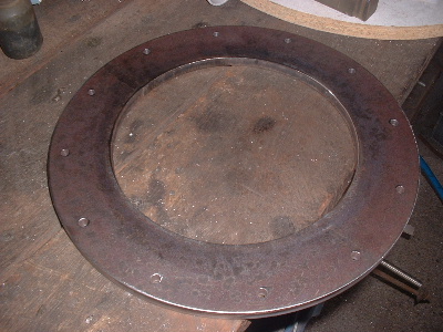
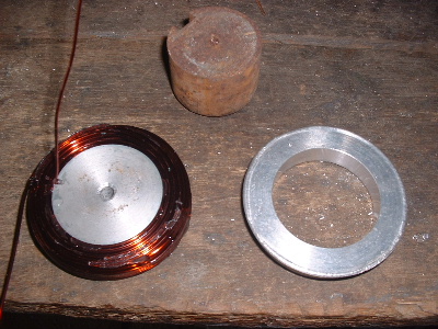
Well it has been a long time in the planning, to build an AXFX. In fact I bought magnets something like a year ago. I had sketched many and varied ways of constructing an AXFX, tossing up whether to start fresh or use existing parts I make. I even contemplated and sketched how to use a trailer hub/axle assembly. The only way to make it real good was to start fresh, make everything to suit, but limited on time, I wanted to cheat every corner I could. The decision eventually was to make an AXFX into the existing White Pointer 2.9. In fact both White Pointers are exactly the same except the blades and cone. But in this AXFX application I will use the 2.9 diameter blades as the starting point. Here is the internals of the White Pointer with a F&P standard shaft and a keyway cut in to drive the AXFX. 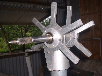 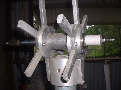
I really don't like rust and so steel, the necessary part, is kept to bare minimum. Also hoping to keep the weight down, but turns out that I only saved a few kilograms. Considering all the extra work, its probably not worth worrying about. Alloy and steel amalgamated. 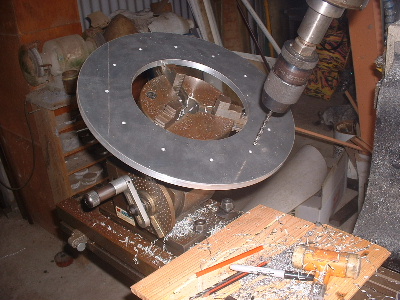 
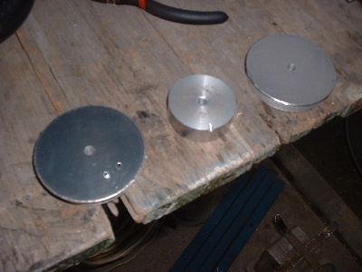
Then painting the back of the steel.  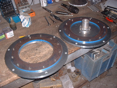
Assemble the hardware to see how it look on the White Pointer base parts. 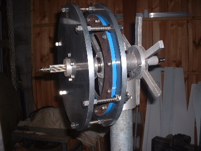 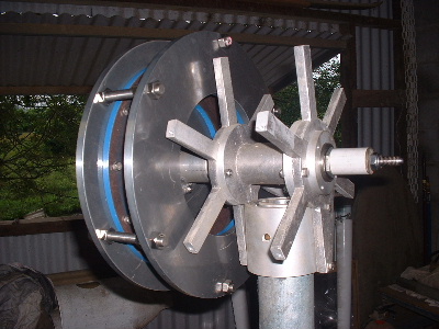
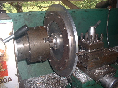
Time to make a wire winder and wind some coils. I have made each coil 100 turns of 1.25mm2. This is the same wire I supplied to Glenn and so I based some guess work on his test coil of 10 turns. I would like to have put more turns in but I had no more space to the 12mm threaded rod that holds the 2 magnet plates apart, or together, whichever way you look at it. The coil winder is in 3 main parts. It has a disk on each side with a centre piece machined to 48mm diameter x 16mm wide. The handle is a pen outer casing over a piece of thread bar! I used PVA (F/glass release) on the wire winder so the araldite will release. Araldite is used to hold the coil together. The sides came away easily, but the centre I hit it out over a machined ring the right diameter. 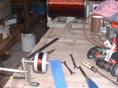 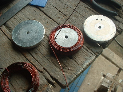
Making up the stator is not as easy as it looks. I could have made up a special mould but always looking for a short cut, I decided to draw the layout on the laminated board. With the centre ring in place and 1 layer of 225 woven glass matt around it, the lines can still be seen on the board. With it wet, I placed all the coils and left it to set. When set, I put on the insulation tape around the edge. 1 coil came loose, so sat a weight on it and wet in some Chopped Strand Matt (CSM). I used polyester resin so could not fill it up all in one go. No good as a casting resin. Laying the CSM and woven rovings in first and then wetting out with resin was a real pain, leaving lots of spikes up around the coils and edges, they just would not go down. After the first layer the edges started to lift from the board, so I had to hold it down with weights. For the last section to fill, I chopped up some CSM into very small pieces and mixed into the resin. In the right ratio it worked a treat. That was so much easier to put in. 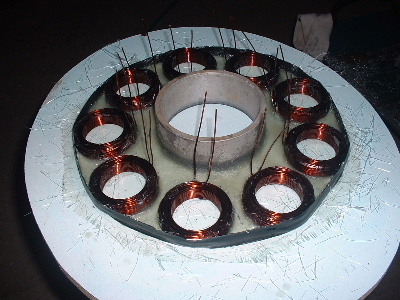 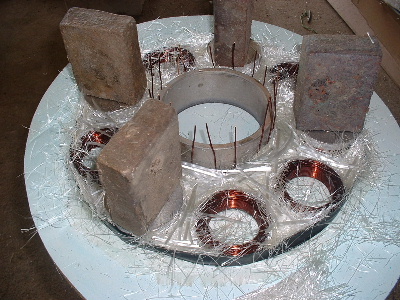
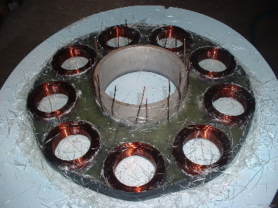 
Started to fit the magnets. Tough little fella's they are. Showing signs of moisture in contact from the thin ply wood that was between them. 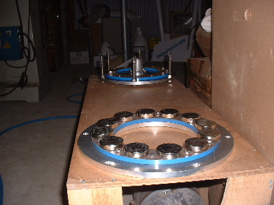 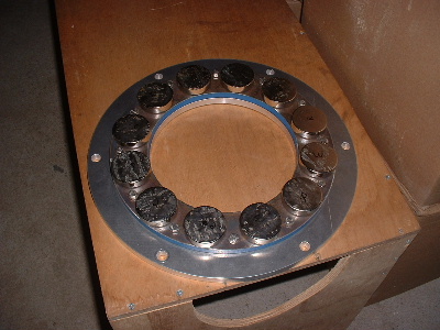
Edit: to put a space between the pictures Trev @ drivebynature.com |
||||
| Gizmo Admin Group Joined: 05/06/2004 Location: AustraliaPosts: 5012 |
Nice post Trev. As always, a professional job. Yeah those magents can be a bugger to separate cant they. Glenn The best time to plant a tree was twenty years ago, the second best time is right now. JAQ |
||||
energy man Newbie Joined: 29/11/2010 Location: AustraliaPosts: 9 |
Very impressive Trev , Bet you cant wait to see this beauty work . Keep up the good work . Duff.  May the wind keep blown folks . |
||||
| VK4AYQ Guru Joined: 02/12/2009 Location: AustraliaPosts: 2539 |
Hi Trev Looking good mate, you went to a lot of trouble with the doubler plates, I look forward to seeing it come together. All the best Bob Foolin Around |
||||
Downwind Guru Joined: 09/09/2009 Location: AustraliaPosts: 2333 |
Bit curious of what voltage mill you are making Trev, as 100 turns per coil dont work out to me. That would be close to the total of 3 coils in series, not per coil, if it was a 24 volt system. Or do you intend to wire the coils in parallel groups of 3.?? Sorry but feel you have a mistake here unless you are going for a higher than average voltage. Pete. Sometimes it just works |
||||
| Trev Guru Joined: 15/07/2006 Location: AustraliaPosts: 639 |
Pete, It is built for 48v. Glenn had for a 10 turn coil test 1.63v at 95rpm, 1.72v at 100rpm, 2.28v at 133rpm. I took the 100rpm = 1.72v x 10 to give 100 turns = 17.2v x 3 coils in series = 51.6v. If you take the 95rpm = 1.63v x 10 = 16.3v x 3 coils in series = 48.9v Cut-in then, should be just before the 100rpm. I wanted more turns to lower the cut-in rpm further but run out of space to the 12mm threaded rod holding the 2 plates. Trev @ drivebynature.com |
||||
| Trev Guru Joined: 15/07/2006 Location: AustraliaPosts: 639 |
These magnets can stop your watch too. I just made that post at 6.51am, my watch says 6.39am. I did notice yesterday when handling the magnets the second hand stopped moving. It has put my watch out 12mins in the few hours I was playing with the magnets. Trev @ drivebynature.com |
||||
niall1 Senior Member Joined: 20/11/2008 Location: IrelandPosts: 331 |
hi Trev thanks for sharing your work , these centrally mounted stators are very different to what we,er used to over here so its very interesting to see one being fleshed out you mentioned you would have liked to have a slightly lower cut in your design... i wonder if by the conversion to dc through rectification you might gain this extra voltage anyway it should increase the v output by a factor of about 1.7 , possibly slightly more with wave peaks those magnets would scare me a lot ....well done ... 
ps ...i looked up Hughs specs on his 3m machine ,its a 12/9 format as well he uses 110 turns of 1.6 for the 48v stator with a cut in of 167 rpm , i know its a very different machine though (smaller block neos 46/30/10mm , different prop etc) so the comparison isnt really so relevant niall |
||||
JimBo911 Senior Member Joined: 26/03/2009 Location: United StatesPosts: 262 |
Trev Ahhhhh yes another job of great craftsmanship, very nice indeed. Glen's AXFX 
Pete's AXFX
Trev's AXFX
Exciting times on the Shed forum. May the Electrons Flow in abundance! Jim |
||||
| niall1 Senior Member Joined: 20/11/2008 Location: IrelandPosts: 331 |
mmm...you forgot shawns as well ....  niall |
||||
| GWatPE Senior Member Joined: 01/09/2006 Location: AustraliaPosts: 2127 |
It seems like forum members have short memories. My contributions have been affected by a 3post limit, but back in the old days, AxFx mills have been made by Oztules and myself as well. There is a lot of info previously posted that seems to go unread. here are some links to some of my work at least. link 1 link 2 It is good that others are now building along a similar path. Well done Trev for the picture book. Gordon. become more energy aware |
||||
| niall1 Senior Member Joined: 20/11/2008 Location: IrelandPosts: 331 |
thats just not true Gordon ... personally the reason i joined the forum was from reading and rereading the posts the older members made ...i know older posts can be lost a little as time goes on , its i suppose the nature of things , the internet seems to have a short memory ..it belongs to youth ,utube and enthusiasm but maybe theres room for both sorry for going off thread here Trev niall |
||||
| Trev Guru Joined: 15/07/2006 Location: AustraliaPosts: 639 |
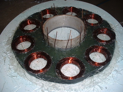
..............and fillm too has posted on his AXFX. I must give all credit to Gordon though, for the info and help to get an AXFX on the go. Gordon's work, experiments & experience is very valuable. It is what I have learned from Gordon that got me excited, more than a year ago, about making one. Thanks heaps Gordon. Well, I have finished off the fitting of the magnets. Getting them apart is a big fight. Marcy helped me a lot to get them apart. When we were down to the last 2, and had no ply between them, I had to try the vice (thanks Glenn). But the vice is made of steel and so you need to be very careful because these magnets have the power to squash your fingers (experience says, it hurts too). With one clamped you can slide the other one off. It is easier to get them off the steel vice than off another magnet. 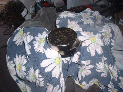 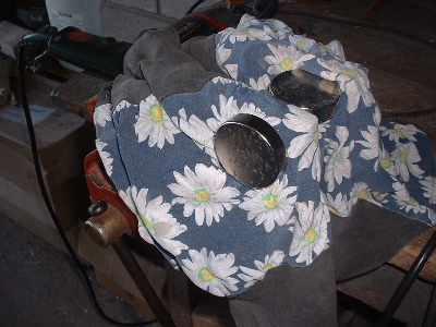
The steel ring is machined to the right diameter for the magnets, so just had to be level on the outside and spaced equally between. The magnets can be slid on the steel or bumped along gently with a piece of wood. I used an aluminium/plastic soft hammer. The alloy is not affected with the magnetic force. the washers added with the wood spacers are 316 stainless steel which is also not affected. But my vernier calipers (stainless steel) are. Sure gives you a fright when they are pulled from your hand and you are not expecting it. My watch is stainless steel, and not affected, except the magnets stop it working while they are close. 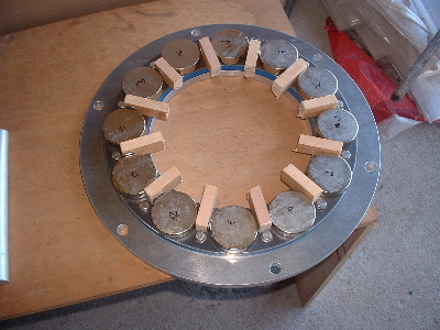 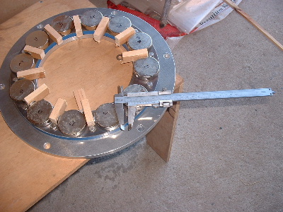
All in place, then are just glued with super glue. With paint on, I went to work on the next bit, drill holes to hold the stator in place. I couldn't remember what drill I used, and habit, just check anyway. I very quickly realized this was not a good thing to do at this point in time. The drill bit was pulled from my hand cutting 2 fingers, not bad thankfully. Anyhow, its the pain that hurts, doesn't hurt anymore when the pain goes away. Just goes to show, you can't be too careful. 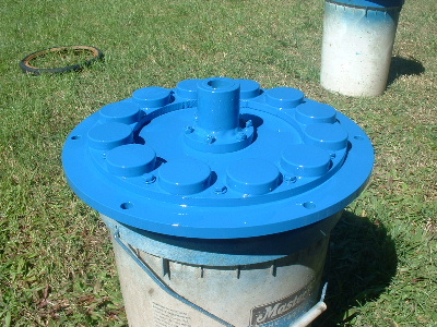 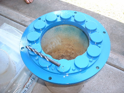
After 5 layers of paint...I hate rust.....I decided to put some silicon around the bolts to ensure the moisture can't start rusting under the bolts. The paint is taking too long to harden up too, so I don't intend to paint again to cover up the brown silicon. 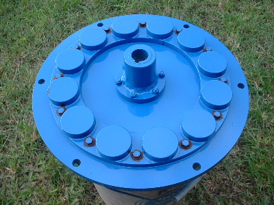 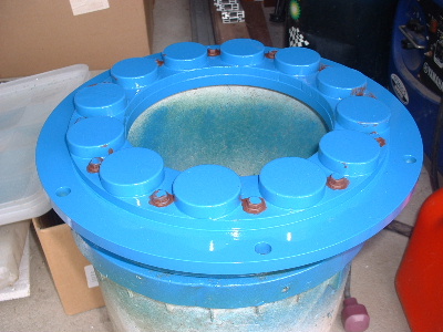
Cleaned up the stator and gave it a coat of resin all over, including the coils. Wired the 3 coils in series. These are all external for checking voltage once I get it all set up. 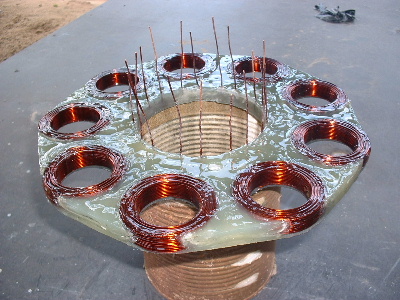 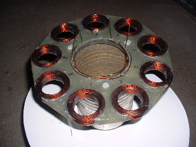
I have put together a new set of blades and balanced them. Getting closer now. Trev @ drivebynature.com |
||||
| JimBo911 Senior Member Joined: 26/03/2009 Location: United StatesPosts: 262 |
Trev SWEET, VERY NICE! Great photo layout to. Thanks Jim |
||||
MacGyver Guru Joined: 12/05/2009 Location: United StatesPosts: 1329 |
Trev I'd be curious to know a few dimensions. In particular, what is the diameter of the magnets and what is their center-to-center spacing distance. Also, what are the coil dimensions (o.d. & i.d.) and what is their center-to-center spacing distance each? The reason I'm asking is from the pictures it looks like you may be creating some cancellation using round coils and round magnets of approximately (by just looking at the pictures) the same diameter and spacing. I realize you have kept the 4:3 ratio of magnets to coils and that's good, but if the same face is to pass over even a portion of both sides of the same coil at the same time, the current induced will be in reverse direction and it will cancel the total charge. I'm speaking from experience here as I use round magnets too and have in the past created some very good-looking NON-working paper weights because I disregarded the effects of magnet-coil placement and dimensions. By the way, a little "Mac" update is due here. I'll be back at it in less than 70 days, when my prison sentence (marriage) ends peermanently. I have to wait until it's "final" before I move on with my life. . . . . . Mac Nothing difficult is ever easy! Perhaps better stated in the words of Morgan Freeman, "Where there is no struggle, there is no progress!" Copeville, Texas |
||||
| Downwind Guru Joined: 09/09/2009 Location: AustraliaPosts: 2333 |
If the coils and magnets are at the same diameter and both are spaced evenly as Trev has shown he has done, than i can not see any problems that Mac is pointing too. There is no other way to align this other than same diameter location of magnets and coils with even spacing between magnets and even spacing between coils. Pete. Sometimes it just works |
||||
| MacGyver Guru Joined: 12/05/2009 Location: United StatesPosts: 1329 |
Pete / Trev Ya, now that I look at it again, it appears the magnets are actually smaller than the coils and on the order of their o.d. being about the same size as the i.d. of the coils. For the magnets to follow in the same diameter as the coils are placed, they would physically have to be smaller or they wouldn't fit, so I guess I was looking at it wrongly. At my first glance, I was thinking they were the same o.d. and was worried it might cancel, having the same face passing both legs of the same coil at the same time. A second look tells me otherwise; old eyes. Sorry for any confusion. . . . . . Mac Nothing difficult is ever easy! Perhaps better stated in the words of Morgan Freeman, "Where there is no struggle, there is no progress!" Copeville, Texas |
||||
| Trev Guru Joined: 15/07/2006 Location: AustraliaPosts: 639 |
No worries Mac, you are allowed to get old. Good info though for somebody who don't know. Thanks Pete. I don't need to say any more. But sombody may want to know. The magnets are N50M, 50mm round x 12mm thick. Coils are 48mm ID and the OD is about 72-74mm. The coils have 100 turns of 1.25mm2 wire. Coils are equaly spaced as are the magnets equaly spaced. The centre of the magnets and coils is a diameter of 246mm. And yes,the 3:4 ratio is the critical bit. Temporary fit the stator to check where to run the wires out and then finish this off. 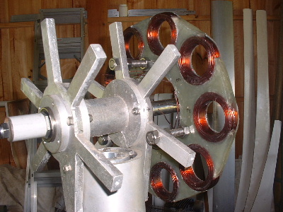 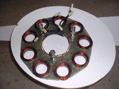
Assembled the AXFX unit and discovered I did need the spacer I made after all, so pulled apart and put in the spacer and machined the front of the rotor hub so the blades would still go on. The jacking bolts are 200mm long and there was no significant magnetic pull at that distance apart. Any how here is a few pictures. 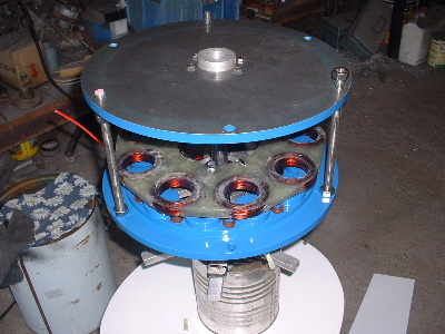 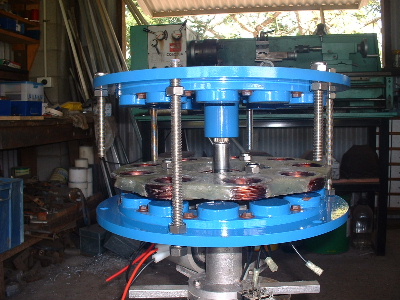
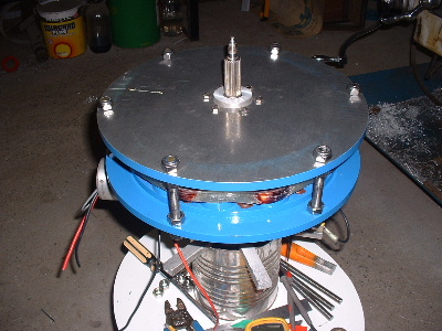 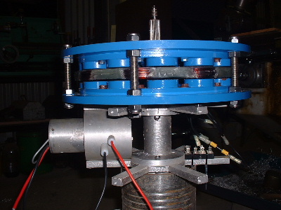
Preliminary spin and yes voltage does occur. Details later after I test properly. Trev @ drivebynature.com |
||||
| VK4AYQ Guru Joined: 02/12/2009 Location: AustraliaPosts: 2539 |
Hi Trev Looking good mat, i look forward to further developments, All the best Bob Foolin Around |
||||
shawn Senior Member Joined: 30/03/2010 Location: New ZealandPosts: 210 |
trev your mill is fantastic is there anything else holding the magnets on except superglu and paint??
what temperture are the mags rated for?? And i was going to ask if you could have used thicker wire because there is still room between the coils but then realized it might increase the stattor diameter to much (for your design) so i will change the question to should i put as thick a wire i can fit??? sorry for all the questions i am still learning. |
||||
| Page 1 of 3 |
|||||
