
|
|
Forum Index : Microcontroller and PC projects : simplest 32MX150 ICSP
| Author | Message | ||||
boss Senior Member Joined: 19/08/2011 Location: CanadaPosts: 268 |
@paceman and @BobD Peter's MMProg 32RPC is working like a charm. Week ago I programmed 5 170 chips. My programming uMite was 150 build on Big Mick PCB, the target chips were all 170's on the same type of PCB. The USB----> 232 was FT232 from ebay. Programming of 186kB file took ~45min with my i7 laptop. The program is reliable and foolproof. Regards Bo |
||||
| robert.rozee Guru Joined: 31/12/2012 Location: New ZealandPosts: 2289 |
i'd be interested to hear what the time was using pic32prog. one thing i am in need of is feedback on how the extended pic32prog performs. cheers, rob :-) |
||||
| JohnS Guru Joined: 18/11/2011 Location: United KingdomPosts: 3659 |
I had a look but the very limited space for a plugin means it looks far more trouble than its worth. A pity. I couldn't fit the central routines in, never mind the rest of the C that would need converting to Basic (if they'd fit). John |
||||
| robert.rozee Guru Joined: 31/12/2012 Location: New ZealandPosts: 2289 |
while a micromite makes an excellent platform for developing a prototype, it simply does not have the necessary computing power to carry out the 'processing per bit' necessary to program an MX150 in a timely fashion. having said this, it is invaluable in emulating untried hardware at a much slower pace. pic32prog, with the micromite 4.5D firmware, confirms that the quantity of traffic to/from the target PIC is: Rate: 153 bytes per second Total TDI/TMS pairs sent = 1582451 Total TDO bits received = 186776 (this is using a 4-wire JTAG interface to the target) with around 1.6 million bit pairs sent to the target, and a desired programming time of, lets say, 2 minutes, that is 1600000/120 = 13,300 clocks per second. this gives you 75uS to do everything associated with getting TDI and TMS from the host PC, extracting the pair from a byte or real, sending them out to the target along with a clock pulse, and in the middle of said clock pulse retrieving TDO and either making decisions based upon or queueing it up to be sent back to the host PC. and there is always going to be a 'host PC', as long as your micromite is not capable of holding the complete .HEX file internally. in 2-wire mode there are 4x the number of clock pulses involved, giving you only 18uS per bit to work within. the only way to achieve this sort of throughput, realistically, is to code everything in C directly, eliminating any interpreted micromite basic code. but then, if going to this extent to achieve speed, why not instead use your host PC to do as much of the hard work as possible? a micromite as intermediate device limits programming to around 15 minutes, no matter what you do. an 8MHz arduino, programmed in C, will hopefully cut this down to just a few minutes. dedicated (non-programmed) hardware should achieve the same sort of time, limited by a desire to keeping the hardware design simple and use only readily obtainable parts. rob :-) |
||||
| JohnS Guru Joined: 18/11/2011 Location: United KingdomPosts: 3659 |
It believe it has plenty to run my C and do the programming in (say) 2 mins. But I need more space than 1K. The interest in doing it is that it would allow multiple mites to be programmed from blank chips as follows: 1. the first, slowly, via FT232RL or the like 2. all the rest, much faster via the plugin feature Potentially the first can be done via MMEdit but it would be quite a paste using a much bigger plugin. John |
||||
| G8JCF Guru Joined: 15/05/2014 Location: United KingdomPosts: 676 |
JohnS is quite correct in his analysis. My existing MMProg32RPC is aimed at people with 150F uMites who either need to upgrade the MMBasic on their existing 150F or wish to program a 170F using their existing 150F. If you've got a PicKit2 then if you need speed, use Pic32Prog . If you've got a PicKit3 then you are sorted anyway. But if you've got a 150F and nothing else, then MMProg32RPC is the simplest/cheapest way to program another 150F/170F - it just takes time, and if "time is money" then go buy a PicKit3, otherwise set MMProg32RPC going, and go have something to eat and drink 
Peter The only Konstant is Change |
||||
| G8JCF Guru Joined: 15/05/2014 Location: United KingdomPosts: 676 |
@JohnS If you made your PIC32 hosted programmer s/w available as a .HEX file, then in a 2 step process, people could use my MMProg32RPC to program your .hex into another 150/170F, and then use the newly programmed 150/170F to program further 150/170F chips at full speed. If you want to do that, then I would happily host your .hex file on my MMBasic website for download purposes if you'd like ? Peter The only Konstant is Change |
||||
| robert.rozee Guru Joined: 31/12/2012 Location: New ZealandPosts: 2289 |
but what of the poor fellow (or fellowess) who only has a PIC32MX150 without anything programmed into it? ie, no micromite or maximite to leverage off. my understanding was that John's .exe only worked reliably on some computers, required a complicated procedure to install drivers that many struggled with, and took an indeterminate time to program a device. as i recall, the same sorts of issues dogged the PIC32 port. please do correct me if i am wrong. john did, however, make sterling progress running on a RPi. and then there is the little open source/GPL issue that is quietly sitting in the corner. cheers, rob :-) |
||||
| JohnS Guru Joined: 18/11/2011 Location: United KingdomPosts: 3659 |
I think the .exe works for most people (faster for some than others) but yes Microsoft's USB driver mess is somewhat painful. (The Linux app works.) Yes, the RPi one is very quick and easy. It's sad to say, really. I hoped to use MMBasic's plugin feature as that "fits" with the overall goal of most people (i.e. using MMBasic) but the small plugin area means it doesn't fit. I might try using the plugin to load my code into RAM and run from there but debugging may be "awkward" not least because I load the PE loader and that loads the PE so this is a multi-way loader. If it runs first time, great. If not, I can see some head-scratching. A standalone MX150/170 hex is my next plan. I need to write some init/support code and choose config bits etc. (I don't happen to have any for 150/170.) Not a killer but it needs more time and I haven't had enough at a stretch. I'd have to choose suitable pins for the 150/170 host (the one doing the programming) to use - any suggestions? I've mainly used the 80MHz chips (and with USB) standalone rather than the 40/50MHz ones (without USB) so am on not quite familiar ground. I have a 220 so might try that next. It's short on ROM & RAM so it may not be doable John |
||||
| G8JCF Guru Joined: 15/05/2014 Location: United KingdomPosts: 676 |
@rr More people have PCs than RasPI's, so a RasPI only version wouldn't be of much wider applicability; and speaking for me personally, altho. I have 2 RasPI's, they are both in 24x7 use acting as servers. If all somebody has is a a single 150F without any code programmed into it, and they haven't even got a PicKit2/3 then IMHO, that person must be expecting some kind of magic to happen - I know MMBasic is "magic" at what it can do, but there are limits ...... 
Anybody just starting out with MCUs could do a lot worse than purchase a 28 pin 170F uMite from Phil at micromite.org which only costs around GBP 5.50. Saving a couple of GBP by buying a blank 170F isn't going to get the newbie anywhere, and anybody who has been playing with PICs will already have at least a PICKit2. Re JohnS's PIC32 programmer, my understanding is that it's got nothing to do with MMBasic, and is a pure compiled C program which boots on the raw PIC32, but I'm sure JohnS will speak for himself. What is the issue precisely ? All the code in my MMProg32RPC program was written by me. Peter The only Konstant is Change |
||||
| JohnS Guru Joined: 18/11/2011 Location: United KingdomPosts: 3659 |
It's all C. I wrote it with porting in mind. That's why it's been so easy to port around e.g. to use libusb to control FT232RL when hosted on a PC, to use direct I/O on a PIC32MX440F256H, and to use (very different) direct I/O on RPi (and to use Linux files on the RPi to read in the hex). Even if the MMBasic plugin area was big enough for the core routines I'd have about 2000 lines to convert from C to MMBasic. A real chore not to mention error prone. I'd rather make it standalone (as on the MX440) or run it from RAM! John |
||||
| G8JCF Guru Joined: 15/05/2014 Location: United KingdomPosts: 676 |
Hi John On a 28 pin PIC32MX170F256B, I use PGD - Pin 5
CLK - Pin 6 MCLR - Pin 7 with my MMProg32RPC program. Peter The only Konstant is Change |
||||
| JohnS Guru Joined: 18/11/2011 Location: United KingdomPosts: 3659 |
Thanks - I'll plan on the same ones unless I hit a problem (which I'll raise if I do). John |
||||
| robert.rozee Guru Joined: 31/12/2012 Location: New ZealandPosts: 2289 |
am in need of a second opinion or two, regarding using ICSP just to erase the flash in an MX150. one of the final hurdles to getting pic32prog usable through the bitbang interface is that released versions of the mmbasic .HEX file have the JTAG ENABLE bit cleared. this poses a slight problem - ic32prog's bitbang unit was originally written with JTAG in mind, but we have no JTAG access. the solution i've been working on is to simply place code in the JTAG head unit (currently a micromite) to perform an ICSP flash erase. in theory, quite a simple process which doesn't even really need the micromite to read anything back from the target. following the microchip datasheets didn't work, so i generating a trace from pic32prog, see below: C>pic32prog -d COM3 BL_JTAG_ON.hex
Programmer for Microchip PIC32 microcontrollers, Version 1.98 (test) Copyright: (C) 2011-2014 Serge Vakulenko Serial communications port initialized successfully *** BETA 02 --- BETA 02 --- BETA 02 --- BETA 02 *** (for "bitbang" support please contact Robert Rozee) ################################ check ID code (in open) MCLR=0 n=46, <eeeeed.edd.DDDDDDDDDDDDDDDDDDDDDDDDDDDDDDDE.ed> read=1 TDO = 0000 0000 14d0 6053 (32 bits) 349200467 (dec) ################################ check status (in open) MCLR=0 n=14, <e.edd.ddfde.ed> read=0 MCLR=0 n=14, <e.edd.fffde.ed> read=0 MCLR=0 n=15, <edd.dffffffg.ed> read=0 MCLR=0 n=15, <edd.DDDDDDDE.ed> read=1 TDO = 0000 0000 0000 008b (8 bits) 139 (dec) Adapter: COM3 ################################ entering get_idcode MCLR=0 n=46, <eeeeed.edd.DDDDDDDDDDDDDDDDDDDDDDDDDDDDDDDE.ed> read=1 TDO = 0000 0000 14d0 6053 (32 bits) 349200467 (dec) Processor: MX150F128B Flash memory: 128 kbytes Boot memory: 3 kbytes Data: 2788 bytes Erase: ################################ entering erase_chip MCLR=0 n=14, <e.edd.ddfde.ed> read=0 MCLR=0 n=14, <e.edd.fffde.ed> read=0 MCLR=0 n=15, <edd.ddfffffg.ed> read=0 MCLR=0 n=15, <edd.DDDDDDDE.ed> read=1 TDO = 0000 0000 0000 008b (8 bits) 139 (dec) MCLR=0 n=14, <e.edd.fdfde.ed> read=0 done Loading PE: 1 2 3 4 (LDR) 5 6 7a (PE) 7b done . . . etc . . . the letters d, e, f, g in the above trace encode TDI and TMS, with TMS = bit 0, and TDI = bit 1. the sequences match up to the constant labels in the source. i've recreated what should be the essential sequences in the following micromite code (partial listing), but it still fails to achieve the desired outcome: ' experimental erase chip via ICSP routine follows erase_chip: Pin(25) = 0 ' PGD (data) --> pin 4 on target Pin(24) = 0 ' PGC (clock) --> pin 5 on target SetPin 25, DOUT SetPin 24, DOUT Pin(25) = 0 Pin(24) = 0 Restore Print "power off" Pin(2) = 0 ' pin 2 is MCLR Pin(7) = 0 ' pin 7 is power on/off (0=off) Pause 1000 Pin(7) = 1 Print "power on" Pulse 2, 0.200 Print "pulsed reset high" Print "sending signature" For I = 1 To 32 Read D Pin(25) = D Pulse 24, 0.005 Print D;" "; If (I Mod 4) = 0 Then Print " "; If (I Mod 8) = 0 Then Print Next I Pin(25) = 0 Pin(2) = 1 ' in theory we are now in ICSP mode Print "in ICSP mode" Pause 3000 Print "sending erase commands" Read D Do Print D;" "; Pin(25) = D / 2 ' TDI Pulse 24, 0.005 Pin(25) = D And 1 ' TMS Pulse 24, 0.005 SetPin 25, DIN Pulse 24, 0.005 ' TDO (ignored) Pause 0.005 Pulse 24, 0.005 SetPin 25, DOUT Read D If D = 10 Then Pause 100: Read D If D = 12 Then Read a$: Print Tab(48); a$: Read D Loop Until (D = 99) Print "erase commands sent" Pause 400 ' in theory, target is now unlocked Pin(7) = 0 ' remove power from target Pause 1000 Pin(7) = 1 ' reapply power, see if still alive SetPin 25, OFF SetPin 24, OFF Print "end of erase" GoTo start Data 0,1,0,0, 1,1,0,1, 0,1,0,0, 0,0,1,1 Data 0,1,0,0, 1,0,0,0, 0,1,0,1, 0,0,0,0 ' "MCHP" Data 1, 1,0,0, 0,0,2,0,1, 1,0, 12, "TAP_SW_MTAP" Data 1, 1,0,0, 2,2,2,0,1, 1,0, 12, "MTAP_COMMAND" Data 1,0,0, 0,2,2,2,2,2,2,3, 1,0, 10, 12, "MCHP_FLASH_ENABLE" Data 1,0,0, 0,0,0,0,0,0,0,1, 1,0, 12, "MCHP_STATUS" Data 1, 1,0,0, 0,0,2,0,1, 1,0, 12, "TAP_SW_MTAP" Data 1, 1,0,0, 2,2,2,0,1, 1,0, 12, "MTAP_COMMAND" Data 1,0,0, 0,0,2,2,2,2,2,3, 1,0, 10, 12, "MCHP_ERASE" Data 1,0,0, 0,0,0,0,0,0,0,1, 1,0, 12, "MCHP_STATUS" Data 1, 1,0,0, 2,0,2,0,1, 1,0, 12, "TAP_SW_ETAP" Data 99 ' these commands in no particular order, copied from pic32prog output ' MCLR=0 n=14, <e.edd.ddfde.ed> read=0 TAP_SW_MTAP ' MCLR=0 n=14, <e.edd.fffde.ed> read=0 MTAP_COMMAND ' MCLR=0 n=15, <edd.ddfffffg.ed> read=0 MCHP_ERASE ' MCLR=0 n=15, <edd.DDDDDDDE.ed> read=1 MCHP_STATUS ' MCLR=0 n=14, <e.edd.fdfde.ed> read=0 TAP_SW_ETAP ' MCLR=0 n=15, <edd.dffffffg.ed> read=0 MCHP_FLASH_ENABLE the output produced from the above is as follows - most of it is just to verify the right numbers are going in the right directions: power off
power on pulsed reset high sending signature 0 1 0 0 1 1 0 1 0 1 0 0 0 0 1 1 0 1 0 0 1 0 0 0 0 1 0 1 0 0 0 0 in ICSP mode sending erase commands 1 1 0 0 0 0 2 0 1 1 0 TAP_SW_MTAP 1 1 0 0 2 2 2 0 1 1 0 MTAP_COMMAND 1 0 0 0 2 2 2 2 2 2 3 1 0 MCHP_FLASH_ENABLE 1 0 0 0 0 0 0 0 0 0 1 1 0 MCHP_STATUS 1 1 0 0 0 0 2 0 1 1 0 TAP_SW_MTAP 1 1 0 0 2 2 2 0 1 1 0 MTAP_COMMAND 1 0 0 0 0 2 2 2 2 2 3 1 0 MCHP_ERASE 1 0 0 0 0 0 0 0 0 0 1 1 0 MCHP_STATUS 1 1 0 0 2 0 2 0 1 1 0 TAP_SW_ETAP erase commands sent end of erase what i see is the code running on the MX150 being halted once the "MCHP" signature has been sent to the MX150, but resuming (ie, has not been erased) once power has been cycled at the end. slightly of concern is that if i change the last bit of the signature, i see the same results. in particular, can anyone see any faults in the way i am getting into ICSP mode? any suggestions would be most welcome... cheers, rob :-) |
||||
| G8JCF Guru Joined: 15/05/2014 Location: United KingdomPosts: 676 |
I don't really understand how it's supposed to work, but the line Pin(25) = D / 2 ' TDI jumped off the page as being out of place in bit-banging, perhaps the line should read Pin(25) = D \ 2 ' TDI ? As I said, I don't really understand what's going on in your code so I've probably guessed completely incorrectly. In My Programmer the sequence is '=========================================================== ======== ' 'ENTER 2-WIRE ENHANCED ICSP MODE 'Section 7.0 Page 19 ' 'Send MCHP, exit with MCLR=1 Initialise '=========================================================== ===== ' ' Set the EJTAG state machine to a specific state ' ' Section 6.1, Page 13 ' The value of mode is clocked into the device on ' signal TMS. TDI is set to a 0 and TDO is ignored. ' ' Send 6 Bits out on PGD ' LSBits first ' SetMode(&H1F, 6) 'Check Status MTAP_SW_MTAP MTAP_COMMAND XferData(MCHP_STATUS) Wait While (Result And (CFGRDY Or FCBUSY)) <> CFGRDY 'ReadMCHPStatus MTAP_SW_MTAP MTAP_COMMAND XferData(MCHP_STATUS) 'Do Chip Erase MTAP_SW_MTAP MTAP_COMMAND XferData(MCHP_ERASE) Wait While (Result And (CFGRDY Or FCBUSY)) <> CFGRDY Chip should now be erased Although I use the PE to do chip erase these days. Peter The only Konstant is Change |
||||
| robert.rozee Guru Joined: 31/12/2012 Location: New ZealandPosts: 2289 |
you are indeed right, it should be "Pin(25) = D \ 2", although in the context it would have worked the same. looking at your code, the error in mine stood out like a sore thumb - i had no equivalent of "SetMode(&H1F, 6)" at the start. within the pic32prog trace this was combined with reading the device ID and i'd completely overlooked it. after adding in the necessary line of code, the JTAG head unit can now erase a JTAG disabled MX150 by simply typing at the windows console prompt "echo * > com3:". many thanks Peter, for your help! rob :-) fyi, here is the complete (now working) code now running on the micromite. it operates with a very simple single-character set of commands (defg DEFG 23458 .>?*) and would easily translate onto a small PIC or similar. the only real requirement is for at least 48 bytes of input buffer and sufficient pins (8 I/O + a fast comm port). ID$ = "ascii JTAG" + Chr$(0) Option autorun ON CPU 48 Option baudrate 230400 ' slow = 38400, fast = 230400 Open "COM1: 230400, 20000" As #5 ' used for buffered input only For B = 2 To 7: Pin(B) = 0: Next B SetPin 2, OOUT ' MCLR, connect to pin 1 on target SetPin 3, DOUT ' TMS, connect to pins 14 and 22 on target SetPin 4, DOUT ' TDI, connect to pin 16 on target SetPin 5, DIN ' TDO, connect to pin 18 on target SetPin 6, DOUT ' CLK, connect to pin 17 on target SetPin 7, DOUT ' status LED (via 1k resistor to ground) ' the following code needs to be fast start: B = Asc(Input$(1, #5)) If (B = 0) GoTo start If (B > &h40) Then Port(3,2) = (B And 3) If (B < &h60) Then Print Chr$(&h30 + Pin(5)); Pulse 6, 0.005 GoTo start EndIf If B=Asc(".") Then GoTo start If B=Asc(">") Then Print "<";:GoTo start ' the following code can be slow Port(3,2) = 0 ' set TDI and TMS low (safety) If B = Asc("2") Then Pin(2) = 0 ' set MCLR low (target in reset) If B = Asc("3") Then Pin(2) = 1 ' set MCLR high (target running) If B = Asc("4") Then Pin(7) = 0 ' turn off LED/power If B = Asc("5") Then Pin(7) = 1 ' turn on LED/power If B = Asc("8") Then Pause 10 ' 10mS (short) delay If B = Asc("?") Then Print ID$; ' generate ID If B = Asc("*") Then GoTo unlock GoTo start ' ICSP erase to unlock devices with JTAG_ENABLE = 0 unlock: Pin(25) = 0 ' PGD (data) --> pin 4 on target Pin(24) = 0 ' PGC (clock) --> pin 5 on target SetPin 25, DOUT SetPin 24, DOUT Pin(2) = 0 ' hold in reset Pin(7) = 0 ' remove power Pause 100 Pin(7) = 1 ' reapply power Pulse 2, 0.200 ' pulse MCLR high For I = 1 To 32 ' send "MCHP" signature Read D Pin(25) = D Pulse 24, 0.005 Next I Pin(2) = 1 ' release reset Pause 100 Read D ' send "erase chip" command sequence Do Pin(25) = D \ 2 ' TDI Pulse 24, 0.005 Pin(25) = D And 1 ' TMS Pulse 24, 0.005 SetPin 25, DIN Pulse 24, 0.005 ' TDO (ignored) Pulse 24, 0.005 SetPin 25, DOUT Read D If D = 9 Then Pause 100: Read D Loop Until (D = 99) Pause 400 ' in theory, target is now unlocked Pin(7) = 0 ' remove power from target Pause 100 Pin(7) = 1 ' reapply power, see if still alive SetPin 25, OFF SetPin 24, OFF Restore GoTo start Data 0,1,0,0, 1,1,0,1, 0,1,0,0, 0,0,1,1 Data 0,1,0,0, 1,0,0,0, 0,1,0,1, 0,0,0,0 ' "MCHP" Data 1,1,1,1,1,0, 9 ' run_test/idle Data 1, 1,0,0, 0,0,2,0,1, 1,0 ' TAP_SW_MTAP Data 1, 1,0,0, 2,2,2,0,1, 1,0 ' MTAP_COMMAND Data 1,0,0, 0,0,2,2,2,2,2,3, 1,0, 9 ' MCHP_ERASE Data 1,0,0, 0,0,0,0,0,0,0,1, 1,0 ' MCHP_STATUS Data 99 |
||||
| G8JCF Guru Joined: 15/05/2014 Location: United KingdomPosts: 676 |
You must be implementing 4 wire JTAG I assume from your code above. Are you going to implement 2 wire ICSP ? Peter The only Konstant is Change |
||||
| robert.rozee Guru Joined: 31/12/2012 Location: New ZealandPosts: 2289 |
Peter: yes, it is the 4-wire JTAG interface that i am working with currently - simply because this is what the 'adapter-bitbang.c' template that Serge prepared for me uses. he created this template by stripping out the USB code from 'adapter-mpsse.c', itself designed to talk to Bus Blaster v2, TinCanTools Flyswatter, and various Olimex programmers based around FTDI's FT2232. the main problem with JTAG is that: (a) it can not erase a pic32 with <bit 2> of DEVCFG0 cleared, as this bit (in hardware) disables the JTAG port when set to 0, and, (b) when using the JTAG interface it seems to be at least difficult (if not impossible) to clear <bit 2> while programming DEVCFG0. i've now overcome (a) with your help, while chatting to Geoff indicates that as long as he doesn't change one small part of his code (b) will not be an issue in future - all past micromite .HEX files have <bit 2> cleared as well as the JTAG interface disabled in code shortly after MMbasic starts up. so having <bit 2> cleared is currently superfluous and hopefully can remain so in future (subject to a few simple tests that need running). 2-wire ICSP is on the roadmap. once i have fully functional and stable code, then the next steps will be: 1. replace the micromite with an Arduino Pro Mini - which will yield significant speed gains and (mostly) solve the chicken/egg problem. to this end i've been reworking my initial handshaking mechanism between pic32prog and the JTAG programming head to allow good throughput with a very small (64 bytes) RxD buffer at the head. the way buffering and handshaking is done is the key to speed. at that point i want to look seriously at getting the code back into the main trunk of pic32prog so that the 'official release' can be used to create a micromite with just a few dollars worth of extra hardware. this largely will satisfy my initial goals when i started this thread. 2. add the ability to compile and run under linux and unix. currently serial port I/O is all done through windows-specific API calls. i'm rather hoping a linux expert will step forward and volunteer to fix this, as a cursory glance reveals a right can of worms. 2. realign 'adapter-bitbang.c' algorithms to make it compatible with 2-wire ICSP programming. this requires several subtle changes in the algorithms used, which i have been loathe to tackle while there are other outstanding issues. it will also require a couple of tweaks in the main body of the pic32prog source, which is strictly in Serge's domain. 3. look at going to a "minimal hardware" programming head, perhaps the LM555 based design i've suggested before, perhaps something even simpler. i've been thinking around an idea using a capacitor and resistor to generate a ramp from xD, which PGD and PGC can in turn be recreated from with just a couple of transistors. i've also been thinking around ideas of programming a pic32 with no TDO feedback from the target. so, much work to do. as long as people are interested, that is. cheers, rob :-) |
||||
| vasi Guru Joined: 23/03/2007 Location: RomaniaPosts: 1697 |
Rob, maybe this can be of help: serial prog. Note: at the end of the page you have a link to a Linux example. There are other cross platform solutions for programming the serial interface: freepascal, freebasic (only for Linux 32bit), commercial PureBasic, Qt library for C++. Hobbit name: Togo Toadfoot of Frogmorton Elvish name: Mablung Miriel Beyound Arduino Lang |
||||
| robert.rozee Guru Joined: 31/12/2012 Location: New ZealandPosts: 2289 |
for the few hundred folks who have been following this thread, the discussion is continuing in the below thread: Topic: simplest PIC16 ICSP with pic32prog (a modified version thereof) now able to talk using an "ascii JTAG" command set, the new thread is centred around getting code into a standalone programmer based around an NPN transistor and a blank PIC16F628A. a schematic exists that looks like it should work - the new challenge is to create a 'firmware uploader' for the PIC16F, then write an 'ascii JTAG' firmware for it. 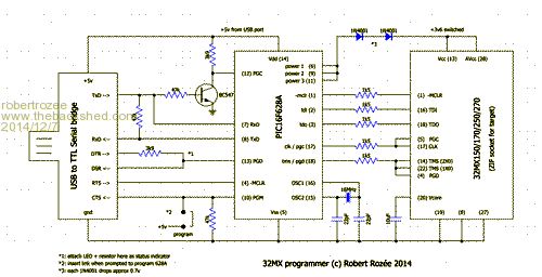
cheers, rob :-) |
||||
