
|
|
Forum Index : Microcontroller and PC projects : simplest 32MX150 ICSP
| Author | Message | ||||
| atmega8 Guru Joined: 19/11/2013 Location: GermanyPosts: 712 |
Should be easy to convert the code to mmbasic if you are familiar with arduino Language. Project Information Project feeds Code license Other Open Source See source for details Labels arduino, pic32mx, Microcontroller, microchip, jtag, pic32 Members tuomo.ka...@gmail.com / ArduPIC32: An Arduino PIC32MX JTAG Programmer! A simple PIC32MX JTAG flash programmer for Arduino. Not optimized in any way, just usable enough for being able to successfully flash a real booloader on the chip. Use of the program should be pretty straightforward: After powering up the Arduino, the PIC32 chip is automatically detected. Pressing 'h' enables the operation and displays the help menu. Press 'e' to erase the chip. Press 'P' to enter programming mode. Once in programming mode, just copy-paste the .hex -file contents into the terminal window. Note that the serial port speed is set to only 1200bps. This is due to the inefficient implementation of the code which I have no plans on improving; Feel free to rewrite if you wish ;-) Below are the instructinos on how to connect Arduino to PIC32MX. Arduino | Connect via | PIC32MX --------------------------------------- PIN 8 (B0) | voltage divider | TMS PIN 9 (B1) | voltage divider | TDI PIN 10 (B2) | straight wire | TDO PIN 11 (B3) | voltage divider | TCK PIN 12 (B4) | 470ohm resistor | MCLR (note: supposing 5V tolerant pin) NOTE: as a voltage divider I used 1.5k + 1.0k resitors. Connect 1.5k to ground, and its other end to PIC pin. Then connect the 1.0k between PIC pin and Arduino pin. NOTE2: check your PIC's datasheet if MCLR is 5V tolerant! It seems that the 5V tolerance is not the same throughout the product line (for example, PIC32MX210F016B has all these pins 5V tolerant and you can use straight wires instead of voltage dividers, but for example PIC32MX795F512H has only MCLR 5V tolerant!!!!) Remember that the PIC32MX itself is generally not 5V tolerant! For 3.3V alimentation I used three (3) 1N4148 diodes in series to lower from 5V to around 3.xV, worked fine enough! For the rest of the schematic, refer to the Recommended Minimum Connection in the datasheet of your PIC32. For PIC32MX1XX/2XX datasheet (61168C), this is found in Figure 2-1. The code has been successfully tested on Arduino NG with PIC32MX210F016B and PIC32MX795F512H. Please let me know if you try with other chips! For more info refer to Microchip documentation: 61145J: PIC32MX Flash Programming Spec 61121E: PIC32 Family Reference Manual, Section 5 Flash Programming / |
||||
| paceman Guru Joined: 07/10/2011 Location: AustraliaPosts: 1328 |
Wow - looks like the Maximite is catered for. The author says to contact him if other chips are of interest for him to test, so a quick e-mail re the PIC32MX150F128B and we might be set already! Greg |
||||
| robert.rozee Guru Joined: 31/12/2012 Location: New ZealandPosts: 2292 |
i'd not be too quick to jump to conclusions - firstly, it is JTAG, not ICSP, and secondly the text only talks about using it to flash a bootloader. i still reckon a solution written in MMbasic provides the most versatility, leading onto a beginner being able to build a very simple (albeit slow) ICSP programmer that itself doesn't require programming (using MMbasic for windows + small usb to digital I/O bridge). rob :-) |
||||
| MOBI Guru Joined: 02/12/2012 Location: AustraliaPosts: 819 |
I did a bit of a test last night and wrote a simple uMite loop routine to programme 10,000 locations (i.e. without hex file manipulations etc) and it took around 15 seconds. I expect it will take a little longer than that with the rest of the number crunching, but if it takes 10 minutes a chip, I can live with that. I've also written the routine to put the PIC32 into programming mode which I'll post when I have a bit of time. Took the Dutch cousins four wheel driving around Lake Bonney in the SE of SA today. Loved it. I guess they don't get much sand hills in Holland. (Not much hills..period) David M. |
||||
| paceman Guru Joined: 07/10/2011 Location: AustraliaPosts: 1328 |
Hmmm... that's a bit deflating, didn't notice that. I'm out of my depth with this stuff - let me know when you guys have it sorted. 
Greg |
||||
| atmega8 Guru Joined: 19/11/2013 Location: GermanyPosts: 712 |
Doe's it really matter if it is jtag or icsp? |
||||
| vasi Guru Joined: 23/03/2007 Location: RomaniaPosts: 1697 |
I tried the Ardupic32 on "PIC32 Pinguino MX220" board which have a PIC32MX220F032D, using an Arduino UNO board and a breadboard for the resistive dividers. Most of the time, will not work(nothing appears on the console). Some times is reporting that it can't recognize the microcontroller and then I have access on other menu options - but is rare. I guess it really needs a PIC32 microcontroller on breadboard with nothing around it apart of power circuit... I don't have one so maybe Dietmar can test it further... __________ BTW, It doesn't matter if is a bootloader or any other hex file... Hobbit name: Togo Toadfoot of Frogmorton Elvish name: Mablung Miriel Beyound Arduino Lang |
||||
| atmega8 Guru Joined: 19/11/2013 Location: GermanyPosts: 712 |
Sorry, no Chance of free time for private reasons.... And i don't have an Arduino;-( And the base idea was to get it running on a PC with mmbasic. So everyone with a PC can Program his own PIC without a special programmer..... It can not be sooo difficult ?! Dietmar |
||||
| JohnS Guru Joined: 18/11/2011 Location: United KingdomPosts: 3669 |
I suppose the idea was to get it working at all. Then later to consider how to adapt it. John |
||||
| vasi Guru Joined: 23/03/2007 Location: RomaniaPosts: 1697 |
Ok Dietmar, now I understood. At first, I thought you came from AVRs considering some of your recommendations and your user ID... Hobbit name: Togo Toadfoot of Frogmorton Elvish name: Mablung Miriel Beyound Arduino Lang |
||||
| MOBI Guru Joined: 02/12/2012 Location: AustraliaPosts: 819 |
No. But the programming technique is quite different between the two (well, at least between 2 wire and 4 wire) If I can get this all to work (and there is no reason why not that I can see) we'll cover both 2 wire and 4 wire and the difference will be obvious David M. |
||||
| MOBI Guru Joined: 02/12/2012 Location: AustraliaPosts: 819 |
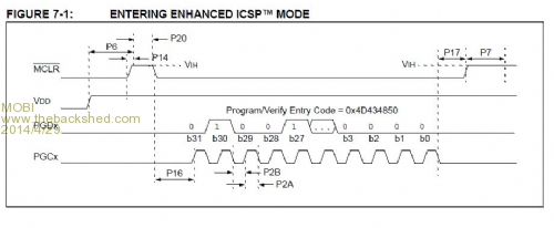
To programme the PIC32, basic wiring should be as for uMite in Geoff's technical manual. Programming mode is entered using the timing chart shown and then clocking in a 32 bit data sequence "MCHP" MSB first. (wouldn't stand for Microchip now would it?) That is the easy part [code] 'pic32 programmer 'this is being tested using a uMite because that is what I have plugged in at the 'moment. '---------------------------------------------- PGD = 14 'pin no. for data i/o PGCK = 21 'pin no. for clock MCLR = 15 'pinf for /reset Dim byte SetPin PGD, dout SetPin PGCK, dout SetPin mclr,dout Pin(pgd) = 0 Pin(pgck) = 0 Pin(mclr) = 0 Pin(mclr) = 1 'reset high then hold low Pin(mclr) = 0 ' output 32 bit sequence MSB first outbyte8(Asc("M")):outbyte8(Asc("C")):outbyte8(Asc("H")):out byte8(Asc("P")) Pin(mclr) = 1 'send reset pin high and hold. End Sub outbyte8(byte) 'clock out 8 bits, MSB first Local x For x = 1 To 8 bit = (byte And 128)/128 Print bit; Pin(14) =bit byte = (byte)*2 Next x End Sub [/code] Looking at the timing chart, it seems that there may be a problem. Time P17 must be a maximum of 100nSec which is outside the capabilities of MMbasic. I'll give it a try but might have to do only 4 wire yet (or devise a MCU dongle - which isn't the general idea. David M. |
||||
| WhiteWizzard Guru Joined: 05/04/2013 Location: United KingdomPosts: 2794 |
Mobi, I have gone quiet on BSF as I am currently having a look at this (using ICSP). What you mention above about P17 is not 100% true about timing (data sheet probably wrong - there's a surprise!). I have recorded and studied a timing capture of an actual programming session. In this capture I am seeing P17 as 2.5885mS . . . so keep going - it should work fine!! For everything Micromite visit micromite.org Direct Email: whitewizzard@micromite.o |
||||
bigmik Guru Joined: 20/06/2011 Location: AustraliaPosts: 2870 |
Lads, Maybe I am sticking my nose in where it doesnt belong. But couldnt a `special' firmware be burnt into a uMite for this very task? What I mean is someone (and NOT dobbing in Geoff as he has done more than enough and needs a rest) writes code in C for a PICMX150 specifically for the task.. Then just a cheap UMIte PCB be dedicated to blasting code into another uMite. (i.e NOT having Basic on board at all) I would be more useless than tits on a bull as I cant speak `C' but I am sure there is a lot of talent out there. Regards, Mick (ducking for cover)  Mick's uMite Stuff can be found >>> HERE (Kindly hosted by Dontronics) <<< |
||||
| MicroBlocks Guru Joined: 12/05/2012 Location: ThailandPosts: 2209 |
If that P17 has to be fast after the last databit then you can probably use the PORT command to set that last bit and change the MCLR at the same time from BASIC. Those two bits will then be set from within the firmware and that is probably very fast. Microblocks. Build with logic. |
||||
| WhiteWizzard Guru Joined: 05/04/2013 Location: United KingdomPosts: 2794 |
Hi Mick, You have the correct concept in my eyes. It has been suggested using MMBasic on a PC - but this doesn't have the I/Os. Using MMBasic on a MicroMite has two things to overcome (both things possible but with compromise): 1> Need to get .Hex file into MicroMite (possible by using an SD reader add-on so not really an issue) 2> Speed. I am currently clocking at 48MHz, and to write a 32bit word via MicroMite I have minimised in code to 7.5mS meeting all timing specs (i.e. can't do faster than this). The PicKit does this same task in 20uS so MicroMite is 375 time slower than PicKit3. Add in all other logic required and at the moment it will be something like 500-1000 times slower. So 10seconds for PicKit (to program firmware currently)= 1hr 23minutes for MicroMite (based on current ratio). I avoid C like the plague (have survived all my life without it and often write PIC applications that outperform the C equivalent) so am not about to learn it now. I am looking at an assembler program to reside on a cheap PIC and then can speed things up to a more 'appropriate' speed. Then make available at a fraction of the cost of a PicKit 3 (possibly free but with same licence constraints as Geoff uses for his MMBasic) Only problem is this is going to take a bit of time before a working solution available. BUT there is demand for this so I will see what I can achieve by the end of the week. Wish me luck! MOBI how are you getting on? WW For everything Micromite visit micromite.org Direct Email: whitewizzard@micromite.o |
||||
| Keith W. Senior Member Joined: 09/10/2011 Location: AustraliaPosts: 118 |
Hi, Referring to the Figure 7-1: ENTERING ENHANCED ICSP MODE shown above. I have a different version of Figure 7-1 from document: - DS60001145M �PIC32 Flash Programming Specification� 2007-2013 Microchip Technology Inc. On the Figure 7-1 (Page 19) P17 becomes P19 with a specification (Page 59) of Minimum 40 ns. No Max given. The DS60001145M perhaps seems clearer than other documents and has had many updates? Keith W. |
||||
| MOBI Guru Joined: 02/12/2012 Location: AustraliaPosts: 819 |
Thanks, that saves me cranking up the cro. I did wonder if the P17 could be longer. It wouldn't be the first time Microchip got delay mixed up with rise time. I think the short time constraint is due to needing the MCLR high before any internal timers kick in. I think the P17 is the only one that is a maximum and all the rest can be mSecs. @TZA - Something like that might work. There are more ways to skin a cat. @Mick, If worse comes to worse, I'll rejig my PICF88 interface for AVRs and PICs but don't really want to go there. Apparently 4 wire programming doesn't need the special "enter program mode" but as I said earlier, most boards are set up for 2 wire ISCP. ===================== @Keith, sorry, I missed your post. Typical of Microchip, different data sheets on the same subject have different info. Surprising I still have much of my hair yet. I'll persist with 2 wire method even if I have to concoct a dongle to interface. David M. |
||||
| JohnS Guru Joined: 18/11/2011 Location: United KingdomPosts: 3669 |
If this all fails, another way might be JTAG via some type of (USB at the PC) FTDI device - various (FT2232 etc) are used in the many JTAG dongles. Then OpenOCD or the like can already program PIC32 chips so no new software would be needed. The challenge would be to figure the cheapest & simplest FTDI chip/circuit. Using mmbasic still needs a way to program the first chip with mmbasic, whereas OpenOCD+dongle would do everything. John |
||||
| vasi Guru Joined: 23/03/2007 Location: RomaniaPosts: 1697 |
Here is a great open source programmer, actively developed. Can do PIC and AVR, 24x memories, 1wire devices, and soon a lot of great features: [quote="Alberto Maccioni"]increase support for PIC and ATMEL micros (as soon as I can get free samples); add ST72, JTAG, parallel memories; expand ICD support; compile firmware also with SDCC [/quote] Definitely, something to keep an eye on. Hobbit name: Togo Toadfoot of Frogmorton Elvish name: Mablung Miriel Beyound Arduino Lang |
||||
