
|
|
Forum Index : Microcontroller and PC projects : *** COMM *** Mick�s PCB offerings
| Author | Message | ||||
| WhiteWizzard Guru Joined: 05/04/2013 Location: United KingdomPosts: 2794 |
@lizby, Is this the cause of your SD card issue in the other thread? For everything Micromite visit micromite.org Direct Email: whitewizzard@micromite.o |
||||
bigmik Guru Joined: 20/06/2011 Location: AustraliaPosts: 2870 |
Hi Lizby (Lance??), I am so sorry to hear that, I will send a couple of replacements to you and a couple of MuP-Proto by means of an apology. Unfortunately these things sometimes happen, especially with the cut price Chinese manufacturers.. I will check all of my MuP3 boards for this fault Can you please confirm that your address is the same and I will have them off to you this weekend. I have attached some screen captures.. If you can pinpoint where you think the fault may have been i can put a closer eye to that area. One is with ALL tracks visible the other has the Vcc highlighted to show where the Vcc line goes in that area. 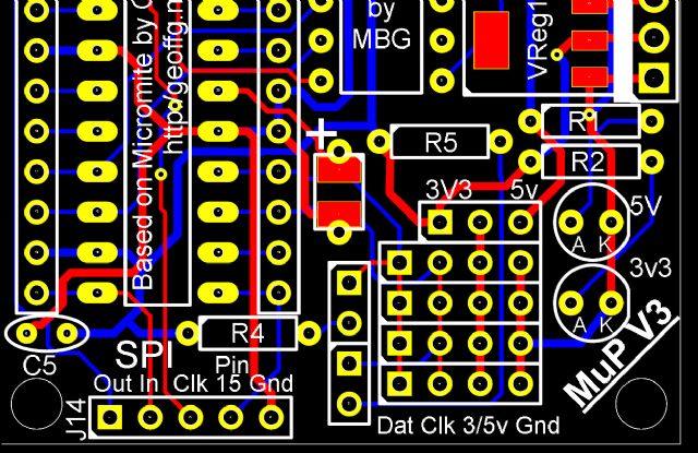 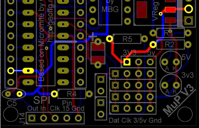 Kind Regards, Mick Mick's uMite Stuff can be found >>> HERE (Kindly hosted by Dontronics) <<< |
||||
| lizby Guru Joined: 17/05/2016 Location: United StatesPosts: 3018 |
No, that was a different MuP3, where I2C worked, and the Arduino-type 5V spi card module used different pins. The sd software worked to read the directory, but didn't to open a file. I'm awaiting the different modules which matherp said worked for him. PicoMite, Armmite F4, SensorKits, MMBasic Hardware, Games, etc. on fruitoftheshed |
||||
| lizby Guru Joined: 17/05/2016 Location: United StatesPosts: 3018 |
bigmic--no apology needed, and no need to send any other boards. All is working now. The top two pins in the DAT column were not linked, and the top one was not linked to the jumper pad to the left and slightly below it (the jumper that links R4 to DAT). If there are no other reports of this, it is possible it is an anomoly, and it's also possible that I did something with imperfect soldering skills. PicoMite, Armmite F4, SensorKits, MMBasic Hardware, Games, etc. on fruitoftheshed |
||||
| lizby Guru Joined: 17/05/2016 Location: United StatesPosts: 3018 |
bigmic--no apology needed, and no need to send any other boards. All is working now. The top two pins in the DAT column were not linked, and the top one was not linked to the jumper pad to the left and slightly below it (the jumper that links R4 to DAT). If there are no other reports of this, it is possible it is an anomoly, and it's also possible that I did something with imperfect soldering skills. I like what these little boards can do--and the whole Micromite ecosystem. PicoMite, Armmite F4, SensorKits, MMBasic Hardware, Games, etc. on fruitoftheshed |
||||
| bigmik Guru Joined: 20/06/2011 Location: AustraliaPosts: 2870 |
Hi Lizby, No worries, the ones I checked here are all OK, it must have been a fault in the exposure process. If you place another order sometime I will toss in a freeby or 3.. Kind Regards, Mick Mick's uMite Stuff can be found >>> HERE (Kindly hosted by Dontronics) <<< |
||||
plover Guru Joined: 18/04/2013 Location: AustraliaPosts: 302 |
Hi Mick, Bottom page 8 in this thread -> https://www.thebackshed.com/forum/forum_posts.asp?TID=6992&KW=Shenzhen2u&PN=1&TPN=8 Here you have the "MuP-Proto" a board full of pads, how did you place these pads, been trying to place lots of pads, real pain unless doing a 'part' even the copy/paste blocks of pads is erratic on my machine. The "MuP-Proto" link is dead [404] by the way,guess some webpage change. |
||||
| bigmik Guru Joined: 20/06/2011 Location: AustraliaPosts: 2870 |
Hi Plover, I dont want to have an extended discussion in this forum as it is my COMMERCIAL advertisment thread and I prefer to keep it that way. If you have other related questions please move them to the PCB manufacture forum of TBS. Thanks for the link info.. Don has changed some things.. I reckon it must be due to those changes.. I will get them looked at as soon as I can. But simply.. I cheated.. I used SIL headers for the pads and simply laid `LINES' down instead on tracks. See my `so called' Schematic. I just bunched them all onto the sheet.. I didnt need a schematic for what I was doing.  Kind Regards, Mick Mick's uMite Stuff can be found >>> HERE (Kindly hosted by Dontronics) <<< |
||||
| plover Guru Joined: 18/04/2013 Location: AustraliaPosts: 302 |
Thanks, now I understand. I have not missed something in DEX. Will try to remember about the thread.  |
||||
| bigmik Guru Joined: 20/06/2011 Location: AustraliaPosts: 2870 |
Hi All, A long time since I started this blatant commercial post.. I have taken my first leap away from the 28pin '170 and jumped straight onto the 64pin EXTREME chip. Using a PIC32MZ2048EFH064-250I. Now I have received my first batch of boards and there are a few minor (most are very minor) issues so I have rectified these and am getting a new batch made up.. If anyone is interested I am offloading these first batch units for `more or less; cost plus a little to cover paypal fees. There are 2 PCBs that I am offering MuP64X A 50mm x 50mm board that was designed to make developing a bit easier, I didn't like the commercial adapter boards and decided to do my OWN.  MuP64X is fairly minimal but has an onboard 3v3 power supply and is intended to be fed via a 5Vdc plugpack (centre Positive). I have NOT built one of these up yet but I am fairly certain it will work OK..The reason I redid this board was simply the numbering on the pinout for the IO headers (I changed some to reflect their purpose ie 3v3, Gnd and Mclr etc). The XTAL oscillator is a very small 3225 size and requires a bit of skill to solder it properly. I will be offering these pre release boards for $1ea plus postage plus Paypal fees. BackPack-64X A 100mm x 50mm, more or less fully optioned board, that I have successfully built up and been able to test most features. It has besides EVERY IO pin accessible in its own right, a connection to a SSD1963 TFT touch screen, (i have mine on a 7" one.) a DS2321M (or DS2323M) High accuracy RTC, support for a winbond 8 pin SOP8 RAM chip (not tested as my chips have not yet arrived). PS2 keyboard and PS2 mouse, microSD card and onboard microbridge chip. 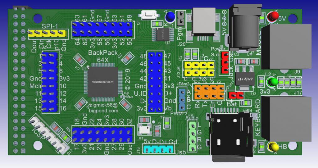 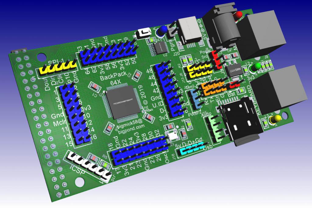 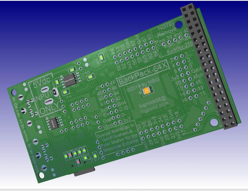 Here it is connected to my 7" TFT (please excuse the crude 6850 battery for the RTC as it was easier to connect at the time.. of course a CR2032 would work just fine. 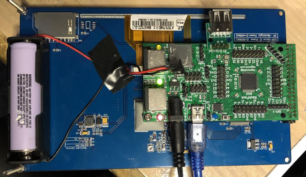 I will be offering these for $2ea plus postage and a bit for paypal fees. The issues I found with this version are as follows: Reset switch Pads are about 1mm too close but i had switches that fit. I lengthened the pads to suit a wider range of switches. uSD socket... The holes for the plastic location `tits' are slightly out of position, I rectified this.. The pads are are fine so just cut the plastic location tits off first. Text (top side) Text for odd pins 17-29 is misaligned by 1/2 hole (0.05") Text (Bottom side) The config text for SD card states 46,10 it should state 46,30 There is a text box with BackPack-64X that overlaps some of the other bottom text looks like a formatting issue. Vbus I sent Vbus to some shorting pads to 3v3, it should have gone to 5V micro-USB Pin 4 of micro-USB socket has a track shoting it to Gnd... doesnt affect anything but it wasnt intended to be there, you can leave it as is. DC Power Jack The Pads for the DC power Jack are actually created as elongated Octagons (bug in DEX) instead of rounded rectangles, as a consequence the copper pour is closer to the pads than i intended.. the ones i tested are still OK but you should chech yours before assembly. I fixed this in the new batch. As a guide, I can send 50Gm in an envelope so the post plus a small bit to cover paypal commission is as follows: AUSTRALIA $1.50 plus the boards you need NZ $3 plus the boards you need Any where else $4 plus the boards you need 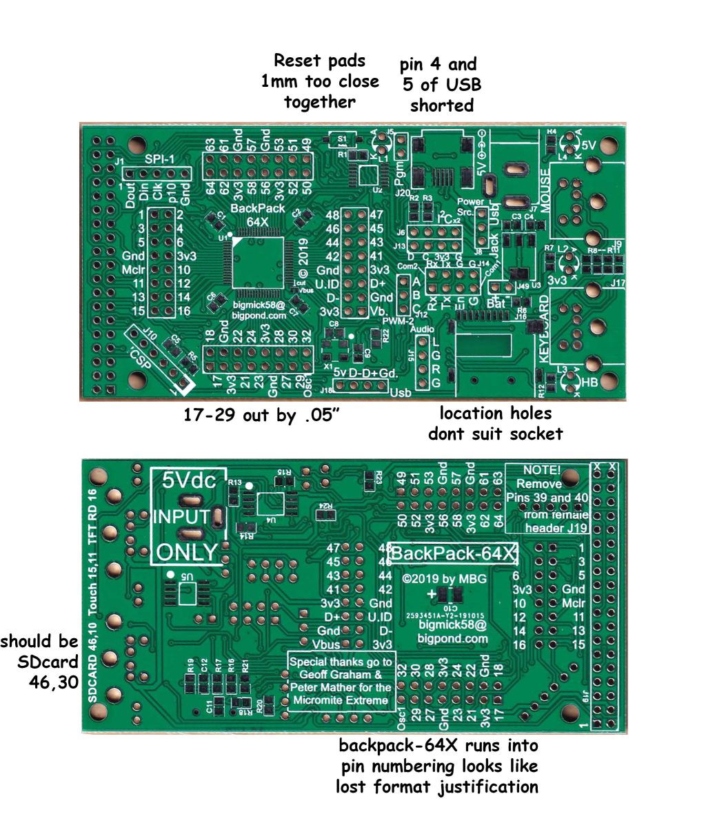 PM me if interested.. I have approx 30 MuP64X and 15 BackPack-64X Kind Regards, Mick Mick's uMite Stuff can be found >>> HERE (Kindly hosted by Dontronics) <<< |
||||
| Volhout Guru Joined: 05/03/2018 Location: NetherlandsPosts: 3558 |
Hi Bigmik, Am I correct asuming the MuP64x board has no gnd pins and 3.3v pins in the io headers? Volhout PicomiteVGA PETSCII ROBOTS |
||||
| bigmik Guru Joined: 20/06/2011 Location: AustraliaPosts: 2870 |
Hi Volhout, No! That is NOT correct... The reason I am offering these pre-release MuP64X is that the SILKSCREEN just shows the MZ PIN number.. I have decided to redo This PCB with pin numbering as you can see in the BackPack-64X PCB. As I am doing a re-run on the BackPack-64X I decided that I may as well redo the MuP-64X. As I have my Right arm in a sling (Due to a major shoulder operation) and it is also strapped across my chest I have not done the manuals yet.. I will do them but typing left-handed (when I am a righty) with one finger is tiresome... There is nothing (that I can see) that is electrically wrong with MuP64X its just the silk screen.. The pins around the MZ chip are exact representations of the MZ pins themselves.. I hope that answers your questions... I still have heaps of MuP-64X but I only have about 8 or 9 BackPack-64X left. There were more significant fixes to be done with BP64X but even those are not too bad. (See my list above) I am redoing them as I like to release a design as close to perfect as I can make them. Kind Regards, Mick Mick's uMite Stuff can be found >>> HERE (Kindly hosted by Dontronics) <<< |
||||
| bigmik Guru Joined: 20/06/2011 Location: AustraliaPosts: 2870 |
GDay All, Today I am releasing the `official' BackPack-64X Version 1.2 PCB I wont bombard with pictures as there is not much physically changed from the `pre-release' versions pictured in the thread above.  BackPack64-X is a 64pin MicrMite EXTREME product that can connect to the back of a 40pin Parallel interface SSD1963 based TFT with Touch screen display panel. Of course it does NOT need to plug into a panel it can run stand alone and those IO pins can be then used for other functions. Features List for BackPack-64X: PIC32MZ2048EFH064-250I/PT 252MHz Processor (also compatible with the PIC32MZ2048EFH064I/PT 200MHz chip) Plugs directly to an SSD1963 based TFT with touch screen support PS2 keyboard support PS2 mouse support USB keyboard support MicroSD support On-board micro-bridge PIC16F1454/5 for USB programming and flash updating of the MZ chip. On-board DS3231/2 high accuracy RTC chip On-board Winbond W25Qxxxx serial flash memory support Convenient headers for SPI-1, Comm 1&2, Dual I2C connectors (in parallel), PWM-2 and indeed every CPU pin. Powered by a 5Vdc 2.1mm barrel jack (preferred option) or via USB with mind to current limitations. The Full manual and associated files for BackPack-64X can be found >>>>> �HERE �<<<<< Version 1.2 changes from previous versions include. Swapped the Winbond memory chip over to SPI-1 (was on SPI-2) Added location holes to the mini-USB connector �J20� Added link options to allow flashing of both PIC chips via the ICSP header Added solder pads to allow access to the RTC chip pins 1 and 3 if needed Increased the pads for the mini switch to cater for even more switch sizes. Made Pin 1 of all IC�s more prominent on the silk screen overlays. As seems to be the bane of my life these days, I fix one thing and break another. I accidentally deleted a 3mm (1/8") track from Pin 1 of the ICSP header but thankfully it is a super easy fix. Full explanation is in the manual. When I do a Version 1.3 I will of course fix this silly oversight. With each BackPack-64X PCB I will also be providing a USB k/b + Audio PCB. Due to the fact that I could not fit USB and 3.5mm connectors for the USB keyboard and stereo output I designed a small piggy back board to connect to the headers I provided for these. It is only a pin adapter and has no other electronics so can be ignored if not required. 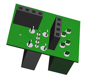 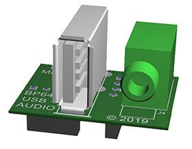 I will be offering BackPack-64X with a USB + AUDIO PCB as a set for $6AU (Approx $4US) plus postage. As a guide to postage in AUSTRALIA it will be $1AU and USA will be $3.50 (approx $2.25US) subject a maximum weight of 50Gm else a small packet is required at $9AU ($6US) If interested please contact me via PM or email me as below (edit as obvious) bigmick58 �AT �bigpond.com A full list of my products I have to offer can be found �>>> HERE <<< Kind Regards Mick Edited 2019-12-17 12:02 by bigmik Mick's uMite Stuff can be found >>> HERE (Kindly hosted by Dontronics) <<< |
||||
donmck Guru Joined: 09/06/2011 Location: AustraliaPosts: 1310 |
Mick just showed me his new BackPack-64X board about a week ago. Very impressive indeed. How much technology has changed in a few short years, and Mick keeps chipping away at his new boards, at ridiculous hobbyist prices. He does postage where he can (which is almost always) at the cost of an airmail letter. You really should do yourself a favor and check them out, if you haven't done so already. Cheers Don... https://www.32v8.com/1 |
||||
| Volhout Guru Joined: 05/03/2018 Location: NetherlandsPosts: 3558 |
Hi Bigmik, I studied the schematics, and have few questions. 1/ u2 pin 9 and 10, where do these pins connect to? 2/ is it correct that pins 14 and 29 are the only free pins? (When using the lcd and rtc and winbond and mouse and kb and sdcard. 3/ is it correct that the audio output shares p45 with j12, but not p53? 4/ why did you use J8, and not the switch inside j7? I will be ordering some boards, and thank you for the ordering codes for element14, that really helps getting the right parts for this layout. Regards, Volhout PicomiteVGA PETSCII ROBOTS |
||||
| bigmik Guru Joined: 20/06/2011 Location: AustraliaPosts: 2870 |
Hi Volhout, You have found a labelling oversight on the Schematic, Thank You I will need to update that. Pins 9 and 10 are by default going to the ICSP header. (On Ver 1.2 and later). I removed the configuration jumpers, on the schematic, for the ICSP header (that selects which chip to FLASH) as it was extremely messy and I thought it was a moot point and was hard to follow seeing how crowded the schematic is. I will probably do a new diagram to show the actual connections for the configuration jumpers and U1/U2 PCD/PGD pins for the sake of exactness. Thank you for pointing that out. I really do not expect anyone to actually change the configuration jumpers (but they can if they wish). I recommend that a pre-flashed PIC16F1454(5) be installed into U2 and then use PIC32PROG.EXE to flash the PIC32MZ.. (Or simply pre flash this before soldering) As to the Element14 P/N they give you an idea of the part, but you can obtain much cheaper prices on eBay or elsewhere. I stock all parts and can quote for parts you need, the difficult with overseas orders is the postage, if the packet exceeds 50Gm the postage goes up from $3.20 to $8.50 (But I can then put 125Gm in). I will adjust the missing labels after I clear the sleep out of my eyes. Kind Regards, Mick Mick's uMite Stuff can be found >>> HERE (Kindly hosted by Dontronics) <<< |
||||
| bigmik Guru Joined: 20/06/2011 Location: AustraliaPosts: 2870 |
Hi Don, Thanks for your kind words, Whilst I think it is one of my better designs, if not the best, the accolades really belong to Geoff and Peter Mather as the hard work in the design of MM and MMX is due to their tireless efforts. But I will let you buy me a beer if you like.  Regards, Mick Mick's uMite Stuff can be found >>> HERE (Kindly hosted by Dontronics) <<< |
||||
| Andrew_G Guru Joined: 18/10/2016 Location: AustraliaPosts: 842 |
Happy New Year to you all. I'd like to second Don's comments about Mick's gear, and particularly, his service - he always goes the extra mile. Now, Mick will always give due credit to Geoff and Peter - and the many others giving of their time and experience on TBS. That is one of the beaut things about "the shed". Please, all of you, all the best to you and keep up the great work. Andrew |
||||
| bigmik Guru Joined: 20/06/2011 Location: AustraliaPosts: 2870 |
GDay All, Thanks to Volhout for pointing out an oversight in my schematic. I have made some amendments to the manual for BackPack-64X and Don has put the latest manual online for me. The latest manual (ver. 1.2a) and associated files can be found >>> HERE <<< @Volhout, Thank you for pointing out the omission. You have some PM's I sent you but not read yet (9 days old) @Don, Thank you for posting the manual and hosting it for me. Kind Regards Mick Edited 2020-01-18 16:32 by bigmik Mick's uMite Stuff can be found >>> HERE (Kindly hosted by Dontronics) <<< |
||||
| Volhout Guru Joined: 05/03/2018 Location: NetherlandsPosts: 3558 |
Hi Mike, Got the white board Backpack 64X build up. A little set back when the trace between the 1454 and the led was damaged. Thought for a while that the chip wasnt progged. But now all works. I most likely will remove the program jumper. Accidentally touching it is anoying will set the 1454 in program mode. Or I will add a 1k pullup.. noticed the 1454 doesn t have a bypass cap. It relies on the other caps on the board. Thanks for the boards. Will start looking for an lcd now. Where do you order them? There seem to be various models, not all compatible. Regards Volhout. PicomiteVGA PETSCII ROBOTS |
||||
