
|
|
Forum Index : Microcontroller and PC projects : MM+: Ultimate Backpack PCB?
| Page 1 of 2 |
|||||
| Author | Message | ||||
| matherp Guru Joined: 11/12/2012 Location: United KingdomPosts: 8582 |
Before going to copper, I'd appreciate feedback on the attached schematic and layout. 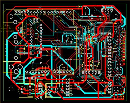
This is for the 64-pin MX470 (MM+) and can act as a backpack for the following displays with the display mounted to the underside of the board. ILI9341 (SPI), ILI9163 (SPI), SSD1289, SSD1963 (any size), S6D0164 It includes an Arduino header which brings out all of the processor pins not already allocated to the TFT displays, touch, SD, Comm1 and 2, PS2 keyboard. There is a PIC16F1455 to provide a USB console on a type-B connector which frees the MX470's USB conection to be used in host mode (type-A connector) for a keyboard and/or mouse as/when Geoff makes host mode available. There is also a PS2 DIN connector allowing direct connection of a keyboard. Of course all these connectors need not be populated on any given PCB. There is a header for a DS3231 RTC module to connect laying flat on the board. The layout fully respects the Arduino UNO pin allocation for SPI and I2C and also includes PWM1A and 1B, Comm1, and Comm2 pins. Dual 5V and 3.3 V supplies are provided and optionally the USB client port can supply the power (link selectable) The mounting holes are spaced to allow a 4.3" SSD1963 display to be fixed securely. TYhe LED pin to relevant displays can be selected between 5V, 3.3V or a PWM'd 5V supply (PWM2B). All surface mount resistors and capacitors are 1206 size so easy to solder. The processor is mounted on the rear of the board to optimise routing. This is by far the hardest layout I have tried to route as every single pin on the MX470 is connected. The layout was done in DesignSpark 7.1 with the component placement and routing done by hand. Minimum track width and spacing is 8mil as recommended by ITEAD. The layout is fully checked by the DesignSpark design rule checker. The PCB size is 100 x 79mm so cost from ITEAD will be USD19.90 for 10 PCBs. All comments appreciated. 2015-08-28_174500_backpack64.pdf 2015-08-28_174518_backpack64layout.pdf |
||||
Grogster Admin Group Joined: 31/12/2012 Location: New ZealandPosts: 9063 |
Nice compact layout, considering all the stuff you have squeezed in there! 
Yes, when you need to route all pins of a SSOP or QFP, track routing can become something of a challenge, as you have found out.  Not an issue, really, if your design can ignore several pins, as that gives you clearance for routing the tracks that you DO need. Not an issue, really, if your design can ignore several pins, as that gives you clearance for routing the tracks that you DO need. 
These PCB's will cost you US$12 for ten from ShenZhen2U. This is the PCB house I use for all my PCB's, and they are superb. ...not to speak ill of ITEAD - they are excellent too. Smoke makes things work. When the smoke gets out, it stops! |
||||
bigmik Guru Joined: 20/06/2011 Location: AustraliaPosts: 2870 |
GDay Peter, Scribble me down for one of them please... Let me know when and how much and I will fix you up.. PM me if you like with details. I do have my own version sitting on the drawing boards but I have had some family illnesses and other issues the past few weeks so I havent yet completed it. My display is also still sitting on the slow banana boat from China... I also wanted to sit back and see where the 64pin and TFT modules `stabilised' and also am wondering how popular the 64 pin will be when/if Geoff gets his 100 pin going. All That aside have you got a good overlay and BOM so I can see what the layout looks like and what parts are needed (assuming you are prepared to part with one). Regards, Mick PS. If you are interested in any of my boards let me know and they are yours. My Feeble Offerings Mik Mick's uMite Stuff can be found >>> HERE (Kindly hosted by Dontronics) <<< |
||||
| JTR0701 Regular Member Joined: 10/07/2013 Location: AustraliaPosts: 71 |
I know that is is just not practical in the case of the USB host routing but at least for the 1455 I would suggest you may easily be able to reroute the USB signal to pin-12 in a similar way to what you have for pin-13. It is just one less high speed signal running between IC pins. To me, that is something to try to avoid. If you nudge the track work around a little it should be doable. The other little-ish (is that a word?) suggestion would be to break out the three unused pins on the 1454 at least to pads, even if not populated at this time. You could put a three pads next to pins 3,4 and 5 and run a red wire around from pin-6. Also very minor but there are a few 90 degree turn tracks that could easily have 45 degree chamfers without causing any layout headaches, of which I'm sure there have been many already. 
Otherwise I hope the board is all good on the first go. |
||||
centrex Guru Joined: 13/11/2011 Location: AustraliaPosts: 320 |
Hi Matherp In your write up of the new board you say the led pin can be 3, 5 or pwm the artwok appears to show the led pin on the 14 pin header direct to 3.3V is this correct. It looks like a great board but I would need the 64 pin chip presoldered. Have you passed over the 44 pin version. Regards Cliff Cliff |
||||
| paceman Guru Joined: 07/10/2011 Location: AustraliaPosts: 1326 |
Hi Peter, You've sure managed to get a lot of capabilities/options on this one - here's some comments which may or may not be useful. 1. Extend tracks a bit to allow for mini (or micro) USB connectors under the type B's, i.e. to optionally replace them. There are a lot of devices/cables out there now that use these. The mini is stronger but I believe it's deprecated these days to the micro, not that that matters. I think Geoff mentioned(?) that was going to use a micro USB connector on the new MM+. 2. Extend the 1206 passive device pads inwards a little to allow 0805 resistors/caps to be soldered - lots of people, like me and Mick,  have standardized on these. It is just possible to solder an 0805 onto a 1206 pad but it would be a lot easier if the 1206 pads were extended inwards just a little - like maybe 0.5mm. have standardized on these. It is just possible to solder an 0805 onto a 1206 pad but it would be a lot easier if the 1206 pads were extended inwards just a little - like maybe 0.5mm.
3. Replace the RTC module with an optional DS3231-type chip. A chip like the DS3232MZ in SSOP package would save a lot of room and be much neater. 4. If (3) above is done there would be (ample ) room for a 12mm (CR1220) battery holder too, to keep things really neat. Just a Gnd & power connection for that helps! e.g. DX.com No. 329253 or RSComponents 219-7926.
5. Is it possible to move the mounting hole (near console header) upwards slightly to better clear the track underneath (possible shorting with screws/nuts) - or does this compromise screen mounting? Greg |
||||
| matherp Guru Joined: 11/12/2012 Location: United KingdomPosts: 8582 |
All - thanks for all the great comments, my responses below. I'm not interested in making/selling these on any sort of commercial basis. Once I'm happy with them and the 44-pin version I'll post the gerbers. I'm also happy to share the DesignSpark design files if anyone wants them. DesignSpark is completely free. If Grogs, Bigmik, or WW want to take them up and supply as bare boards, kits, ready built, etc. that would be fine. 2015-08-29_074323_backpack64.pdf 2015-08-29_074345_backpack64layout.pdf Thanks - done Done Hopefully I've now found them all. Fixed, it was correct on the 40-pin header but wrong on the schematic for the 14 pin No, the two versions are intended to be complementary Next job is to annotate all the pin numbers etc. onto the silkscreen and do a BOM Great , I'll give them a try. See introduction I'm confident on the pin layout of the original A and B connectors, less so on the mini or micro so I'll stick as is. I route tracks through the 1206 pads so changing some and not others would be a big job. I'm happy to share the design files if anyone wants to mod in these or any other ways. DesignSpark is completely free. The module is much cheaper than the chips etc. and easier for a builder No, the layout is to screw directly to the 4.3" SSD1963 display, but I've moved the tracks slightly to gain more clearance on this hole |
||||
f1fco Senior Member Joined: 18/03/2012 Location: FrancePosts: 154 |
hello, if it will be a (small) production, I wish 1 board thank you Pierre, from Nimes, south of France 73s de F1FCO |
||||
| Zonker Guru Joined: 18/08/2012 Location: United StatesPosts: 761 |
Excellent layout Matherp..!
This PCB has a lot going for it... The 4.3" display size should work well for many types or projects.. Laying out a board is a lot of hard work to get just right... If a run of these become available, I would like to have a play with one or two... What is the best 4.3" display to order for the PCB..? Will get some ordered... Tip of the hat to you fine Sir for sharing the PCB design..!! |
||||
| centrex Guru Joined: 13/11/2011 Location: AustraliaPosts: 320 |
Hi Matherp Another question you don't appear to have allowed for the connection of the SD cards on the displays is this deliberate for some reason. Regards Cliff Cliff |
||||
| matherp Guru Joined: 11/12/2012 Location: United KingdomPosts: 8582 |
Not sure I understand, the SD card pins on the 40-pin header are correctly wired unless I've made a mistake - always possible. The SD card pins for the ILI9143 SPI displays are at the other end of the display from the 14-pin connector and the position varies with the display size (2.2", 2.4", 2.8") so I haven't tried to include these. However they can be wired into the appropriate holes in the 40-pin header using flying leads. |
||||
| centrex Guru Joined: 13/11/2011 Location: AustraliaPosts: 320 |
Hi Peter I don't know if the above schematic is the latest version? You appear to have D3 for the Arduino listed as pins 48 and 32 on the 64 pin chip? Bit hard to check on the actual layout. Am I seeing things or is there a later schematic. Cliff Cliff |
||||
| matherp Guru Joined: 11/12/2012 Location: United KingdomPosts: 8582 |
Hi Cliff There was a labelling error which I've corrected. I've also simplified the power supply and got rid of one 3.3V regulator. I've also now added the SD card pins for a 2.8" ILI9341 display (far left of the pcb) and I've changed the PIC16F1455 wiring to match MicroBlocks latest circuitry. I think now I'm ready for fabrication other than to improve the silkscreening 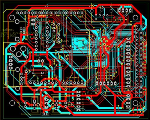
2015-10-05_102907_PCB.pdf 2015-10-05_102920_Schematic.pdf |
||||
| centrex Guru Joined: 13/11/2011 Location: AustraliaPosts: 320 |
Hi Peter The reason I asked is that I have a Skinnymite which I have converted to an MM+ by fitting the xtal as you suggested but it still required a breadboard which I don't like. So I thought I would make a mother board with the Arduino base layout. I have brazenly copied your pin allocation, that is how I found the error. Unfortunately the usb pins were not brought out on the Skinnmite so there will be no usb. The board will have the 14 pin layout for the ILI9341 displays as well as the 40 pins for the other displays as per Geoffg allocation. The boards are in production at the moment, unfortunately with a couple of errors, oh well that's what wire wrap wire is for. Thanks for the updated schematic. Cliff Cliff |
||||
| matherp Guru Joined: 11/12/2012 Location: United KingdomPosts: 8582 |
The PCBs arrived this morning so I've built one up
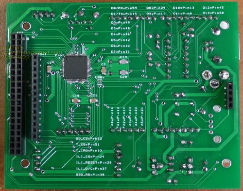
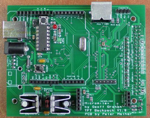
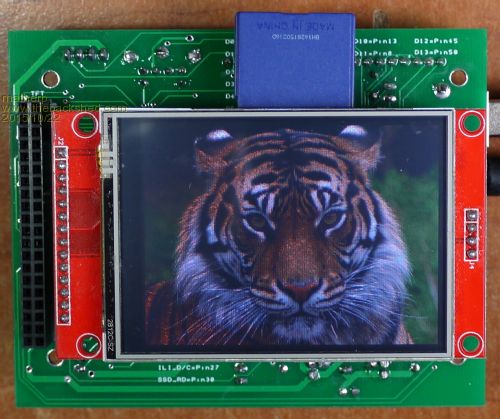
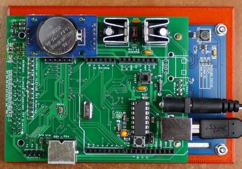
Everything works perfectly. The spacing of the headers allow a 2.8" ILI9341 display to be plugged in so that both the display/touch and the SD connections are active and working. The 40-pin header enables all three functions on SSD1963, ILI9325, S6D0164 and SSD1289 displays. Backlight for displays other than the SSD1963 can be controlled by PWM 2A. Power is jumper selectable between USB and the standard power connector. The USB console is provided by MicroBlock's excellent PIC16F1455 software and the wiring on the PCB support this programming the Micromite+ firmware using PIC32PROG via the PIC16F1455
Headers are provided to plug in a standard DS3231 real-time clock module which works correctly on I2C. A standard PS2 keyboard connector is provided making it easy to turn into a standalone computer with no additional wiring. Finally, I/O pins are made available via the Arduino header which conforms to the Arduino UNO pinout for UART, SPI, I2C, and analogue connections. Everything works and so far I have only found one minor layout issue: an Arduino board overlaps very slightly the DS3231 module. This is still workable but can be fixed in any second version. The missing connector is for a USB-A for when Geoff implements a USB keyboard . Alternatively there is a shorting link provided to use this as a USB-B CDC device by using a crossover A-A cable. So a console port can be used direct from the MM+ if required.
If anyone wants the gerbers let me know. I used ShenZhen2U.com to produce the boards following Grogster's recommendation. Cost to me including delivery �1.64 each for 10-off. |
||||
| WhiteWizzard Guru Joined: 05/04/2013 Location: United KingdomPosts: 2794 |
Looks very neat Peter. Out of interest, is that a 2.4", or a 2.8" Tiger? This PCB would be the perfect quick test for understanding if my 'LOAD IMAGE' issue is due to my TFT; but annoyingly I have now soldered my TFT pins 
One annoying thing with the BackLight connected to PWM is that whenever you go into the built-in editor, the display goes off (since EDIT claws in all system resources resulting in the PWM being switched off). This is assuming that Geoff's LIBRARY mm.edit sub feature is still 'removed' from the firmware. Any suggestion for a workaround? (other than using MMEdit!). WW For everything Micromite visit micromite.org Direct Email: whitewizzard@micromite.o |
||||
Lou Senior Member Joined: 01/02/2014 Location: United StatesPosts: 229 |
Peter, great looking board. I'm checking with Zonker now to see if he wants to split an order of boards. If so, we'll get the gerbers from you. Thanks for the offer and the hard work. Wizz, is that a fly on the tiger's nose ?? Thanks, Lou Microcontrollers - the other white meat |
||||
| paceman Guru Joined: 07/10/2011 Location: AustraliaPosts: 1326 |
Great job Peter, very impressive integration and having Jean's (MicroBlock's) USB/firmware insight and effort included is true 'icing on the cake'. Amazing what you can do with a GBP 1.64 board, a few components and some really well developed software.
Greg |
||||
retepsnikrep Senior Member Joined: 31/12/2007 Location: United KingdomPosts: 131 |
What is the bottom of the 4 pictures showing? It appears to be a bigger screen attached? What is it thanks? Gen1 Honda Insights. |
||||
| panky Guru Joined: 02/10/2012 Location: AustraliaPosts: 1094 |
@Peter, great job with this board. I see the schematic you posted but do you also have a BOM with sources? @Lou, if you and Zonker go ahead, can I buy a couple of boards from you please? Doug. ... almost all of the Maximites, the MicromMites, the MM Extremes, the ArmMites, the PicoMite and loving it! |
||||
| Page 1 of 2 |
|||||
