
|
|
Forum Index : Electronics : OZInverter Main Capacitors
| Author | Message | ||||
| Solar Mike Guru Joined: 08/02/2015 Location: New ZealandPosts: 1123 |
I read somehere on the forum that others were having issues with the OzInverter 10,000uf 100 volt capacitors being very leaky. I purchased mine from This AliExpress Store ,of the 10 in the order, 6 of them have excessive current draw when the voltage goes above approx 70 volts. I have placed one is series with a 10k resistor and a 95 volt supply to limit the leakage current, will leave it in this state for a day or so to see if it reformats its internal oxide coatings. Fingers crossed. We just cannot trust these suppliers, its not only the mosfets now its the capacitors, Ahrrr... Mike |
||||
Grogster Admin Group Joined: 31/12/2012 Location: New ZealandPosts: 9060 |
Yes, those ones are the EXACT same ones I got - same seller, same listing. I will be VERY interested in your results of your "Soak test"  as I would like to know if mine are likely to also be duds. as I would like to know if mine are likely to also be duds.  Looks like I will have to bite the bullet and spend a fortune at Element-14 for some genuine factory ones. I guess I should not really be that surprised. Anything that is too good to be true, probably isn't...... EDIT: Probably IS! ...but I leave the original in there so you can have a chuckle at my expense.  Looking forward to your results.  Smoke makes things work. When the smoke gets out, it stops! |
||||
| Solar Mike Guru Joined: 08/02/2015 Location: New ZealandPosts: 1123 |
Well after leaving overnight one cap connected to the 95v supply via 10k resistor, the voltage across it this morning was 75 volts, went up a volt or so thats all. Retested them all again this morning, set current limit on the supply to 15ma and 95 volts, so they couldnt blow up. Four reached full voltage over a minute with no leakage, the rest zipped up to 70 odd volts over a minute then sat there drawing 15ma current, the voltage wouldnt go any higher. If I had connected up without the current limit set no doubt they would have shorted out at the 70 volt mark due to excessive internal heating. 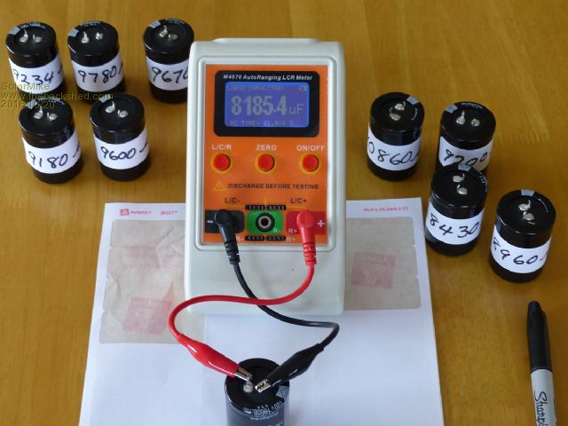 Discharged them all using a 5 ohm resistor then shorted for a minute and tested on a capacitor tester, see photo, Results in uf: 8185 8430 8960 9180 9200 9234 9600 9670 9780 10860 So only one > 10,000uf and that was one that is leaky above 70 volts, four definitely are low. Basically none of them are any good, measuring other old computer power supply caps they nearly all exceed their marked values. The inverter runs up to 56 volts on my system, so guess they arent leaky at that voltage, but they are all lower value than spec, could use the top six possibly....  How critical is the total = 60,000uf, my guess is even 60k is a little low for high current surges. Other professional inverters I have worked on in the past would use > 100K uf here. How critical is the total = 60,000uf, my guess is even 60k is a little low for high current surges. Other professional inverters I have worked on in the past would use > 100K uf here.Grogster, if you want I can test yours for you if you dont have a tester, PM me. Cheers Mike |
||||
Madness Guru Joined: 08/10/2011 Location: AustraliaPosts: 2498 |
The Caps are there to smooth out the ripple caused by switching at 100HZ (counting both sides of the sine wave). They are not intended to provide surge current, having sufficient size cable etc will take the load off the capacitors as far as I know. There are only 10 types of people in the world: those who understand binary, and those who don't. |
||||
| Solar Mike Guru Joined: 08/02/2015 Location: New ZealandPosts: 1123 |
I looked in Element14, they have one snap in type 10,000 100v for $37 each, RS Components have zip, couldnt find any other NZ supplier. 63 volt is more common, cutting it a bit close though. If I buy any more online, will have to test them soon as they arrive in order to raise a dispute if they are faulty. |
||||
| joebog1 Senior Member Joined: 07/11/2015 Location: AustraliaPosts: 114 |
Those of you that have an ABN can also try WESCOMPONENTS.com Their caps are full spec, and I havent had any failures. I use their caps in popular blue inverters made in melbourne. They may be still more expensive than some are prepared to pay however. Joe |
||||
oztules Guru Joined: 26/07/2007 Location: AustraliaPosts: 1686 |
We are getting a little bit precious about this folks. Rated capacitance is very liberal for electrolytic caps. Series E3 caps have a tolerance of +-20% ( stamped "M" ) Series E6 caps are +-20% ... marked "M" again, and the expensive E12 series are rated +-10% coded as "K" tolerance specs from IEC 60062 So all the measured caps are within tolerance... so would not bother with the dispute process for uf measurement. Providing they don't explode at 65v and less, they are just fine for this project. I use the $4 ones, and they stay cool at power levels below 4kw with my leads, they are also cooled by the fans when the heat sinks exceed 32C, so never get above that I suspect... short 10kw excursions will not cause any problem, as this will only last for seconds or less. In short... I would not lose any sleep at all over it. The crappy fets seem to work very well too, there is a lot of give in the design for off grid normal use. The QLD boys with 24hr airconditioning would do well to build a few, one for the aircon, and one for the house, and this will keep everything under 4kw per unit for prolonged periods... then any fets and caps will probably do fine for many years. ............oztules Village idiot...or... just another hack out of his depth |
||||
| Solar Mike Guru Joined: 08/02/2015 Location: New ZealandPosts: 1123 |
Point taken  yes they are in 20% tolerance, they might explode at 75 volts, I will just use the best six. yes they are in 20% tolerance, they might explode at 75 volts, I will just use the best six.Bit more research done and the 100 volt ones are generally 70mm high, anything 10,000uf and 35*50mm would be 63 volts probably. Some 80v ones are 50 to 70. Ideally from a design perspective they should be low esr types to keep the losses down during high peak ripple current transitions to achieve greater than a 2000 hr lifespan. Currently I have a 3.5KW high frequency sinewave inverter running and it had all sorts of RF hash off the battery cables, caused by switching transients, after replacing the supply caps with low esr types and slightly more capacitance, most of the crap has gone. Mike |
||||
| oztules Guru Joined: 26/07/2007 Location: AustraliaPosts: 1686 |
HF inverters are a totally different case. The caps are critical for energy storage in the HV stage, or the wave can't be formed under load, hence the skinny surge char. These inverters seem to work with no capacitance at all for a fair bit of their rating, as they use the battery for energy storage, not the HV caps like the HF inverter does. The caps do less work with big leads and more work with skinny leads, but the sine wave will appear in the battery leads regardless of how much capacitance there is, as the energy storage is only the 1/2E^2xC. This means that the voltage is the prime part of the energy storage as it is a square function, the capacitance is only linear, so a big change in the C has less effect than a similar change in E.... just another reason not to go 24v or 12v. Practice has shown that temp is a function of size, and there is no linear relationship between heat and capacitance.... more caps is better as there is more surface area, and less ripple per aluminium foil.... so you will find say 1 cap will get to 80c yet 4 caps doing the same work won't heat at all. Leakage will generally be because of storage, and should come back to reasonable levels with self healing from practical useage..... ie the oxide layer is formed from voltage, the higher the voltage, the thicker the oxide layer. Storage can make the layer deteriorate, and become less like a diode, and more like a resistor as the insulating layer is eroded in storage. Your size is captive to the oxide layer thickness, and the surface area structure. Modern ones are over 200 times the effective area than a flat plate scenario. It seems nearly all modern improvements have come from surface area improvements in order to get them smaller... but the heat has less area to get worked out is the problem... once again, more caps is better, rather than better caps in most cases. Not sure where your going to be getting the 75v from, if it is fine at 60v then it should be practically good. I would hope self healing will begin after that anyway, and your measured leakage will come back a bit then. As usual with electro's ......regardless of the theory, temp will be the best indicator of what works, and the life span hoped for.... or suck it and see in situ would describe it best. Caps are an unknown ... even to the manufacturers.... stick em in and test the system out.. then you will know for sure what works for your unit, and what you can get away with.... keep the current paths heavy. ..........oztules Village idiot...or... just another hack out of his depth |
||||
| Solar Mike Guru Joined: 08/02/2015 Location: New ZealandPosts: 1123 |
Thanks Oztules for your excellent explanation.  I will be leaving one hooked up via 1k resistor to 95v supply to see just how long it takes to self heal, if at all, connecting direct to a 75 volt supply they draw about 100ma leakage for the worse one. Mike |
||||
| joebog1 Senior Member Joined: 07/11/2015 Location: AustraliaPosts: 114 |
Without raining on anyones parade oztules has it in one regarding capacitors, and some of you may remember that I pointed out life of electrolytics and temperature in a previous post. Today electrolytics are cheap!! Really cheap, 99% of them these days coming from some part of Asia, even if labelled some other country. Temperature and lifetime are directly related! Easy way to understand is hot cap = short life cool cap = long life And my photograph before showing some big Siemens caps shows the surface area that oztules addresses in his post. I have some of these caps replacing the large bank of small "computer grade" caps by short flying leads ( 6mm^2) I have another inverter with origional puter caps that I can measure leakage and ( for me) ESR also on short flying leads. The third inverter is with caps on PCB. The remote caps show MUCH less ageing !!That is, the remote caps have far better ESR and much lower leakage ( still only a couple of mA ) than those mounted on the PCB. Ease of construction is why we all ( even me ) place caps on the PCB, but when it comes to power supplies we need reliability more than brute force, or power available, at least to my way of thinking. Designing a modern inverter is now way beyond my capability, but my experience with capacitor ratings, I think still applies. Keep em cool!! use "buss bar" type solid copper connectors to keep the impedance low, and put the caps as the first pass behind the fan, so that the caps get the coolest air. Its awful hard to measure temp in a capacitor can!. Excellent topic, as I am even remembering stuff I forgot years ago Joe |
||||
| Grogster Admin Group Joined: 31/12/2012 Location: New ZealandPosts: 9060 |
|
||||
| Tinker Guru Joined: 07/11/2007 Location: AustraliaPosts: 1904 |
While the 10,000uF/100V capacitors that many builders are using in their inverter project are fine for the job, I also purchased more expensive ELNA capacitors for a different reason. With my copper strip power tracks, soldering the snap on capacitors is a real pain. It requires a huge gas powered soldering iron and the risk of cooking the capacitor during soldering. So I ordered 6 x ELNA 10,000uF/100V screw terminal connection caps, which arrived today. They are twice as tall for the same diameter, an added bonus as the heat dissipation surface is twice as large. Charging them up to 90VDC via a 1K series resistor, the mA meter in line showed around 0.5mA when the 90V potential was reached. This probably reduces to nothing if I waited long enough but I'm happy with the no leakage results on all 6 caps. At $70.00 for the six not cheap but I think I got what I paid for. Klaus |
||||
| Solar Mike Guru Joined: 08/02/2015 Location: New ZealandPosts: 1123 |
Yes I have some of those low esr types from an old TV transmitter switch mode power supply, as you say they are twice the size and weight, mine are about 35 years old and havent been used for 20 years, I tested 6 of them last week for possible use in my second inverter and they seem 100%. The original suspect caps that I left on a 90v power supply via a resister havent reformed themselves at all after some weeks, I suspect they are 63 volt or similar and have been re-packaged as 100 volts, best used for some other less demanding application. Since ordered replacements, just waiting for them to arrive. |
||||
| Solar Mike Guru Joined: 08/02/2015 Location: New ZealandPosts: 1123 |
I am re-designing my inverter to use more modular H-Bridge sections with the mosfets bolted direct to 25mm x 25mm sq aluminium bars, a small cct board sandwiched between another bar that the sources bolt to. The small cct board will contain the TC4452 driver for each module. Four modules are used to make one H-Bridge, the drain connected bars are bolted via a thin mylar film sheet to the flat heatsink base. Similar in principle to the Large Power IXFN360 Mosfet modules that others are looking at, I'm using IRFP4468 devices for very low RDS(on), 4 in parallel per module. Modules will be linked via 50mm sq flex cable and crimped connectors bolted to each allow bar. This allows me to use quality screw terminal caps for the supply, I really dont like those PCB mounted ones, the cheap chinese ones are rubbish really, their ESR is quite high, so have sourced some old UPS screw terminal 30,000uf 75volt from Casa Modular Systems, they will be ok for a trial and should keep the supply ripple down. 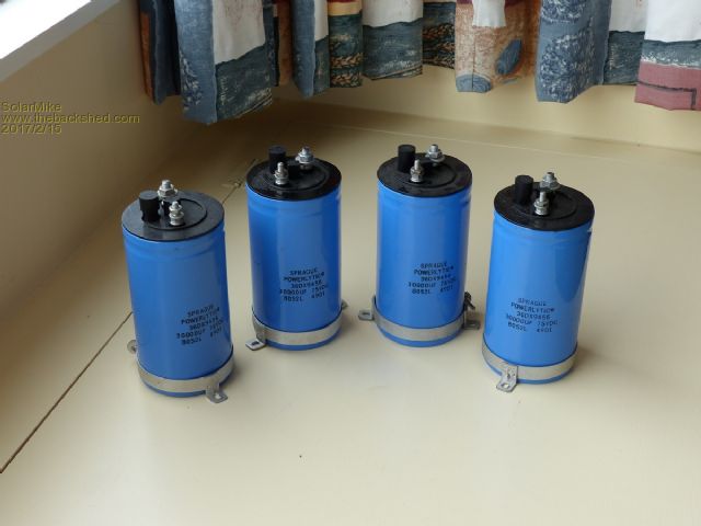 A plug for Casa here, they have a good range of second hand screw terminal caps all sorts of voltages and prices are good. Hopefully if this works, I can use the same modules for other non-inverter applications like very high power SSD relay replacement. Will post some details when I have one built. Cheers Mike |
||||
