
|
|
Forum Index : Electronics : Various aspects of home brew inverters
| Author | Message | ||||
| poida Guru Joined: 02/02/2017 Location: AustraliaPosts: 1388 |
I have run the cheap inverter boards from a nanoverter and it works fine in testing. I needed only to make a cable that takes 10 pin IDE plug to the 0.1 inch single inline socket the EGS002 plugs into. And an extra wire to supply the nanoverter with 48V (I now use and test on the bench only 48V systems) But those cheap boards have some problems in my view. capacitor size is OK, but I prefer bigger, they might reduce large current pulses from coming out of the inverter and messing with solar charge controllers. I have a long running inverter based on a rather expensive board from Aliexpress that has individual gate resistor/diode/gate->source pull down resistors for each MOSFET. This is the better design in my view. Anyway, the inverter has provided about 1.3Mwhr without problem and is now sitting ready to power the house should the bigger and better inverter based on Madness's totem pole drive and my nanoverter ever blow up. If you are thinking to make an inverter you have the right idea. Over size the power board, have large heat sinks, have good sized fans. Finding a suitable transformer might be a challenge. The chokes are easy to make, get about 50uH and large air gaps in the cores to ensure saturation is way, way above any running condition's current levels. a good, large and expensive board is this one which Ben & Amber are using. if I was buying one now I would probably get something like this I like to disable the 2 over current protection since I think both circuits can drive the MOSFET bridge in such a way as to severely stress things. I prefer to place a simple DC contact breaker on the DC supply, and limit current that way. You might have more fun and get much more help from here if you instead build the power and control boards yourself. wronger than a phone book full of wrong phone numbers |
||||
| Clockmanfr Guru Joined: 23/10/2015 Location: FrancePosts: 427 |
Hi djull, Regards OzInverter and the 8010 SMD Chip. For the FET Driver Chips power supply we now use 15v zenner diode. Please be aware there are many Fake driver chips out there. For further background info about the power supplies and why we use what we do. see ..... https://www.anotherpower.com/board/index.php?topic=1116.30 Oztules on the problems with the egs002 002 Board and why the 002 board was disgarded. From �.. https://www.anotherpower.com/board/index.php?topic=1116.30 "I got the razor blade out and removed the 393... shorted pins 7 to 8 and then made a jumper from 1 to 4. This gets the inhibit pins of both the drivers and the main chip to turn off (/ or on depending how you want to say it I guess) ... unequivocally.... ie they no longer get to inhibit anymore. Then use the current IFB input as designed. It then behaves with no problems. I cant understand why they used the 393 in the first place, unless the IFB signal from their resistive sense was too small, but they needed to get the timing correct so that the IFB pin on the main ship got the message first, but that is not the case. They decided to inhibit in three places at the same time..... and failed miserably. Not noticed with EI transformers ( but for odd noises), but lethal for torroids..... now it is fine, and I can use the current o/load in the chip to do the stop... test.... stop ... test etc, then turn off needing hard start. The current transformer ( CT) has plenty of output, and needs attenuation and a small filter to behave nicely. I still prefer the temp TFB pin for on and off at this stage. Now it seems I can try all I might, but cannot fool it into blowing the fets.... up to 2.5kw at least. 2kw ( 2 fets/leg) and it runs for quite a while before it starts to warm up much at all ( 10 mins), and thats with no other cooling... very useable now." I trust this helps? Everything is possible, just give me time. 3 HughP's 3.7m Wind T's (14 years). 5kW PV on 3 Trackers, (10 yrs). 21kW PV AC coupled SH GTI's. OzInverter created Grid. 1300ah 48v. |
||||
| djull Newbie Joined: 28/10/2019 Location: FrancePosts: 9 |
OK thanks for the info. Just to be sure, transfo turn ratio is Vout/Vin with �Vin = Vbat_min/sqrt(2) ? Is there a synchronize function to parallel 2 inverters in your controller board ? Or lot simpler with one big inverter but 2 transformers with one which could be disabled or enabled according to power demand with big amp relay ? As transformers are coupled on the outside, I don't know how it works but as victron did such system, it should be interesting for idle consumption and maybe easier to make & find 2 or 3 small toroid than 1 big one. Edited 2019-10-30 20:02 by djull |
||||
| poida Guru Joined: 02/02/2017 Location: AustraliaPosts: 1388 |
Turns ratio: my system has a 48V lead acid battery. I choose to run it at any voltage above about 48.5V and so this is the smallest peak to peak voltage of the primary when running the PWM at maximum modulation. People here have found that it's best to have some headroom to allow for power transients and differing loads. We usually settle on about 80% modulation to deliver the required primary winding AC voltage. So with my 48.5V minimum, I multiply this by 0.8 and get 38.8V, round it to 39V This the the peak to peak AC voltage of the primary when driven at 80% power with 48.5V DC supply. I want 230V AC RMS output from a primary winding that is 39V P/P = 27.6V AC RMS Turns ratio is 230/27.6 = 8.33 to 1 With the 3kVA toroid found inside the 3kVA Aerosharp grid tie inverter, I find I need 27 turns for the primary winding. There is a sync. function on the nanoverter. Use it at your own risk. I developed the code and hardware to enable experimentation. This function has not been used yet as far as I know. I had a 3kVA Victron. It died exactly one month after the 2 year warranty elapsed. This gave me the energy to develop home built inverters. Switching the second transformer: The sudden power input into the transformer core will place huge loads on the inverter bridge. Maybe consider a soft start switch. eg relay number 1 switches the second transformer primary into circuit via a large resistor. Maybe 2 seconds later relay 2 shunts the resistor. Then full power may be drawn from transformer 2 and to be certain of this, have another relay that connects loads to the second transformer output maybe a short while later. Voltage regulation will present challenges. But most devices run well enough within a range of AC input voltages. You can reduce voltage sag to a large extent with large area primary winding cable, DC supply cable etc, and using large toroids. wronger than a phone book full of wrong phone numbers |
||||
| Warpspeed Guru Joined: 09/08/2007 Location: AustraliaPosts: 4406 |
This is indeed all very true. The grid voltage goes up, down, (and probably sideways sometimes) and all of your household appliances work just fine off the grid. An inverter too need not maintain an extremely tight output voltage tolerance. But although the grid might SLOWLY vary over an amazingly wide voltage range, hour to hour, you can pull massive short term surge currents from the grid and it hardly notices. An inverter on the other hand, may suffer mightily with very heavy and sudden step changes in load. The usual complaint goes something like "the lights flicker whenever the fridge or air conditioner starts up". So what is arguably more important is speed of response to load changes rather than maintaining a constant long term never varying output voltage. Voltage feedback can only start to correct after the output has changed, and can only correct so fast, without becoming unstable. If it over corrects, it may start to surge, and that can be catastrophic. So feedback correction needs to be quite gradual and controlled. Voltage feed forward is a completely different concept to voltage feedback. The dc voltage is measured at the INPUT to the inverter, and that sets the inverter output voltage directly. If the battery voltage goes up 8.2% the inverter reduces the output voltage by exactly 8.2%. It can correct instantly without any possibility of instability. So its much faster in operation. The disadvantage, is that as inverter load increases the output voltage will fall off slightly, but then so does the grid ! My own 5Kw inverter drops off by roughly about 2V per Kw of load. So no load I might see 235v, and at 5Kw about ten volts less than that. That makes no discernible difference to any household appliance that I have. But the big advantage is absolutely minimal or no light flicker, depending on the type of lighting you have. Cheers, �Tony. |
||||
| djull Newbie Joined: 28/10/2019 Location: FrancePosts: 9 |
Thanks for the info. I didn't take any margin in my calculation as I would accept some voltage variation at the output but seems make sense to have some margin here. Does the ratio have an incidence on idle consumption ? I saw that with more turns on both sides, it tends to decrease, but physically hard to put everything inside the core. Very interesting Warpspeed. I prefer too have a more stable output at the price of small voltage variation with load. Grid can becomes very low in winter here at the end of the line in the campaign : <200V sometimes instead of 230V)... And everything works. In my mind battery voltage was fairly constant with very small variations, especially with lifepo4, so it is still difficult for my mind to understand well this kind of regulation, but if it works, I have to update my knowledge :) Only your specific warpverter design is able to do this Vfeed fordward ? Or any nanoverter can do this (with small modifications to mesure the DC input voltage instead of rectified 230 vac) ? I will take a closer look on this point. Seems interesting for reliability. |
||||
| Warpspeed Guru Joined: 09/08/2007 Location: AustraliaPosts: 4406 |
Battery voltage is far from constant even with Lithium Iron. Assume you are in the late afternoon, the battery is fully charged and at maximum permissible voltage with only very small final charging current, say 100mA. Then your 4Kw airconditioner decides to cut in drawing �about eighty amps (at 48v). I can assure you that the difference in battery terminal voltage between 100mA charging and 80 amps discharging voltage is not small, even with a very large Lithium Iron battery. The feed forward technique is widely used in many applications where speed of response is vitally important. Take for example a modern vehicle with electronic ignition. There will be a lookup table of engine load versus rpm that sets the ignition timing. For every possible combination of speed and engine load inputs, there will be a defined optimum ignition timing point. No need for any kind of feedback. In fact feedback is not really possible. With an inverter its dead easy. �Only one input, and one output. The transformer turns ratio is fixed, so without changing anything, the ac output voltage will be proportional to dc input voltage. Both go up and down together. If input voltage changes, the output will change by very close to the exact same amount. If you arrange things so that any correction of output voltage is EXACTLY inverse to changes at the input, the output should remain constant. There is nothing new or radical about this. �Its just not a generally a widely known or understood method of controlling things. Its very easy to apply to any inverter that has some electronic method of output voltage control, especially where there is a microcontroller. There are all kinds of secondary issues about controlling inverter output voltage as well. How do you actually measure the amplitude of a sine wave that is constantly swinging up and down throughout each cycle ? �You cannot just take an instantaneous snap voltage reading, unless its right at one peak. �And you can only do that twice each cycle right at the very peak. The reading must be averaged somehow, and that takes at least one whole cycle, maybe several for any accuracy. �So if your air conditioner suddenly starts up, and the inverter output voltage suddenly drops by thirty volts, it going to take some small time to realise that something fairly dramatic has happened, and the output needs to be slowly ramped back up. Measuring the incoming dc is much easier. �You can measure it a thousand times each second and know exactly by how much its changed within one millisecond. �And then apply that change to the inverter either instantly, or change the gain at the next zero crossing to exactly compensate, without introducing a sudden step into the waveform. Its hugely faster, correction is total and exact, and with zero chance of any surging or instability. We don't need voltage feedback because the inverter itself is weak, we need it because the incoming dc voltage sags and rises horribly under extreme changes in loading. If we can correct for that really quickly, we should end up with something that can really minimise sudden voltage dips and peaks. Edited 2019-10-31 18:16 by Warpspeed Cheers, �Tony. |
||||
| djull Newbie Joined: 28/10/2019 Location: FrancePosts: 9 |
If I well understood, theoretically, with a nano board and at the price of 2 inputs and some software work, we can get the better of the 2 worlds with a quick correction with the input DC sense, and make very slow changes (order of the second or more) by checking the average AC output voltage. But it may becomes too complicated with small gain so not interesting to do. If I have to choose I prefer the input regulation no doubt of that. I'm asking myself why it is not more used here on diy nano based inverters ? I can understand that a commercial product with a proportional voltage drop with charge.. not good for the quality image I searched poida nano control schematic and found nothing. It is somewhere ? Clockman, I took a look on your links and the first regarding power supply seems not the good one. Edited 2019-10-31 22:40 by djull |
||||
| BenandAmber Guru Joined: 16/02/2019 Location: United StatesPosts: 961 |
Poida the great guided me on how to do my first China board inverter and it just keeps on surprising me seems like it won't blow up! be warned i am good parrot but Dumber than a box of rocks |
||||
| Warpspeed Guru Joined: 09/08/2007 Location: AustraliaPosts: 4406 |
That would certainly be the next logical step forward, but if you actually build and test a feed forward system you will find that the performance is good enough that anything more is just not worth the trouble. The mains wiring in the house is going to produce voltage drops in the wiring when really heavy loads switch in and out anyway. I really have no idea why nobody else does this. It actually reduces the number of components on the inverter board. Fewer parts mean less things that can fail or go wrong. Cheers, �Tony. |
||||
| Clockmanfr Guru Joined: 23/10/2015 Location: FrancePosts: 427 |
Hi djull, Because of spikes, torroid, power etc etc. 24th March 2016. "The weakness in this version of experimental (OzControl) board is the rudimentary power supply. The 7805 is prone to failure in further bench testing.... and that takes the chip out. It didn't happen in the first board as I must have been lucky at turn on. In the pj board, the caps must have slowed the inrush currents enough to protect it, but a second one on the bench into a small transformer with no filtering failed a few times on start up ( instantly) and took a few boards with it.... So I have run out of boards for the time being, and won't risk the one on the big transformer, so bench testing will stop until new victims arrive, and a new board with better power supplies and other changes are done.... obviously tried to make it too simple. I'll keep the big one running until they arrive, just to continue the power testing.. but it looks strong once up and running so there is much hope. in short don't do that board unless you better the power supply. The next board will have plug in chips so I can be more gruesome in the testing of it. 26th March 2016. In the quest for power supply stability on switch on, decided to make it tip35c for both 12v and 5v with 120R and 100uf capacitior to dull the start up spikes.... seems to have quelled all resistance from that quarter. If the damn thing didn't work so darn well, I would make the triple pwm supply and get away from the 2110..... but it works so well, I can't justify it on performance terms.... Oztules" I trust this explains why the OzInverter control board uses TIP35's. Everything is possible, just give me time. 3 HughP's 3.7m Wind T's (14 years). 5kW PV on 3 Trackers, (10 yrs). 21kW PV AC coupled SH GTI's. OzInverter created Grid. 1300ah 48v. |
||||
| tinyt Guru Joined: 12/11/2017 Location: United StatesPosts: 431 |
I think the latest design files are here |
||||
| djull Newbie Joined: 28/10/2019 Location: FrancePosts: 9 |
Thanks a lot warpspeed, clockmanfr & tinyt. I ask myself why nano control board need 2oz pcb ? Clockmanfr :If I well understood, it is a bulletproof design in order to avoid some problems when power it on FIRST time with big inrush current. No problem with just small ON/OFF switch and inverter plugged and cap charged. Right ? Maybe a soft start design here would have avoid this kind of problematic ? Warpspeed : I saw that on poida nanoboard, AC out voltage sense ( through transformer and diodes) goes not "directly" to nanoboard as DC battery sense but trough LT1638 opamp. I ask myself if it is necessary to protect nano input against some transients or something else regarding accuracy reading. As nanoboard already have DC input sense, it may just be software mod to get feed forward system. But PCB design may be too simple here to get speed and accuracy, I don't know. I have just very basic electronic knowledge and I don't understand very well the big difference between DC battery voltage sense and AC rectified sense :). Edited 2019-11-02 02:40 by djull |
||||
| tinyt Guru Joined: 12/11/2017 Location: United StatesPosts: 431 |
No need for 2oz for this control board. I am just used to thicker copper clad which does not delaminate as easily as 1 oz when repairing the pcb. |
||||
| Murphy's friend Guru Joined: 04/10/2019 Location: AustraliaPosts: 582 |
OK, so, bearing in mind my modest experience, we already have a nano input (A0) sensing a small DC voltage and using that to correct the inverter's AC output voltage. Does anybody have a circuit that senses a proportional DC battery voltage instead? I would be happy to build that and try it, or is my way of thinking here just too simple  |
||||
| djull Newbie Joined: 28/10/2019 Location: FrancePosts: 9 |
In fact nanoboard (at least Poida one) already sense DC battery voltage through a very simple schematic. It is used just to display battery voltage I think and maybe sort of stop/ alarm in case of too low or too high Battery voltage, but not used for regulation of the output 220/230/240 AC. But actual hardware battery sense may be insufficient to make proper regulation with Warpspeed idea, I don't know. It should be interesting to have Poida opinion about this. |
||||
| Warpspeed Guru Joined: 09/08/2007 Location: AustraliaPosts: 4406 |
It should be possible, provided the dc voltage being sensed follows the incoming dc changes fairly rapidly. In other words no huge electrolytics to smooth the measured voltage. We want to see those rapid changes ! Then its just a case of writing some simple software to adjust the pwm duty cycle with a straight line linear relationship of duty cycle versus measured voltage. Pwm duty cycle 100% at minimum dc input voltage. Pwm duty cycle reduced to 50% at twice the minimum voltage. My big Warpverter uses no microprocessor. The incoming dc voltage is just measured with a nine bit analog to digital converter, twenty five times each second. Zero dc volts = 000 Half scale dc voltage = 100 Full scale voltage = 1FF I just use the lower eight bits 00 at the half scale minimum dc voltage. And FF equals full scale voltage (twice the minimum voltage). That addresses 256 different lookup tables in prom. Each lookup table is 1K and contains a slightly different amplitude sine wave. It jumps from one lookup table to another at the exact zero crossing point so that the output voltage waveform shows no discontinuity even with massive gain changes. 256 lookup tables give better than a half volt difference between lookup tables, so the output amplitude changes are very smooth and imperceptible. It would all be a lot easier with a microcontroller, but you may still need a whole bunch of lookup tables anyway. So its just as easy to do it all in hardware. Just an ADC and a prom, and that is really all it takes. Cheers, �Tony. |
||||
| poida Guru Joined: 02/02/2017 Location: AustraliaPosts: 1388 |
part 39: Transformer saturation Time to discover a bit about the toroid. I have a modified version of the nanoverter code that lets me control the AC output frequency, with a range from about 60Hz down to 40 Hz, always maintaining the AC output voltage. The test is a prototype inverter, into a 95uH choke and 1500W toriod. I am using the Aerosharp 1500W toriod and it's factory 230V secondary winding. I have an output AC voltage of 245V AC as measured by Wiseguy's Power Mate Lite. There is no load on the AC output. It is possible and easy to plot the B-H curve of a transformer. A good and readable background on magnetics and B-H curves is found here B is flux density H is magnetising force I like also the pdf of magnetically soft materials where a nice B-H curve is shown for a typical example. B is vertical axis H is horizontal axis. 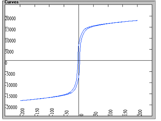 For these toroids the B-H curve will be a narrow rectangle, very tall and not very wide when there is no saturation. This is because the Iron core is very magnetically soft. It will take any magnetic field and suck it all up. It will also not keep any remnant magnetism after the field goes away. Compare that with a (magnetically) hard material like a permanent magnet as found in a hard drive. It takes a strong field strength and keeps it when the field stops. You can get the two quantities needed to plot the B-H curve easily. The X axis is current. The Y axis is the integrated voltage across the winding. Lots of DSOs can do maths on the inputs but I choose to use Excel to do the integration more accurately. I thought it might be interesting to see the B-H curve for the above 1500W toroid excited to 245V, even though it seems to be specified for 230V AC on the secondary. I would expect some saturation at 50 Hz. We know that when you drive a mains transformer, and this toroid is a "mains transformer", at higher frequencies you get less tendency for saturation. And when you drive it at a lower frequency than 50Hz, you will see more and more saturation. 50Hz, the is the beginnings of saturation, where the top and bottom of the narrow rectangle are drawn out to the right and left. 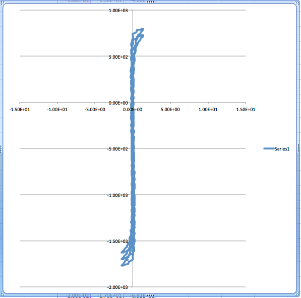 60Hz, nothing at all 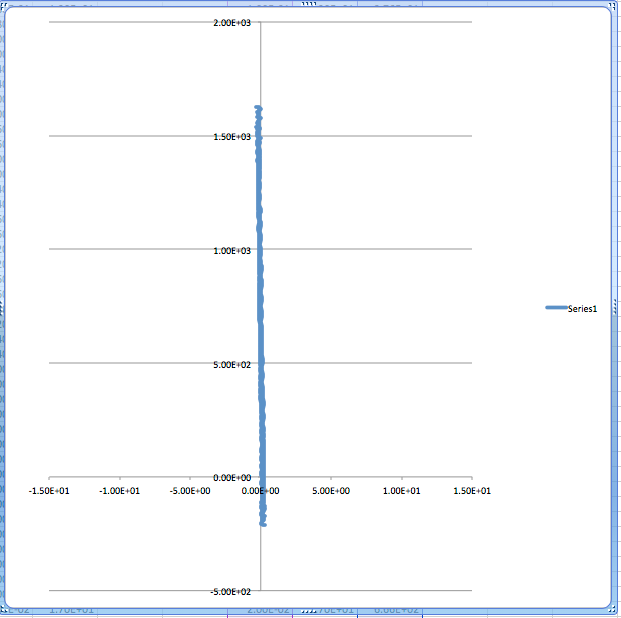 and 44Hz, where there is a lot of saturation. 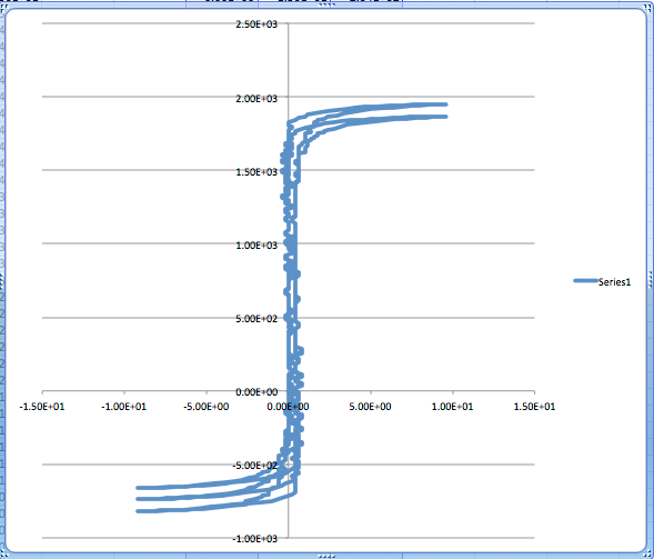 All 3 graphs use the same horizontal axis scale, which is current. The vertical axis is the integral of the AC voltage as measured at the secondary winding. Here is the current and voltage at 40 Hz. Purple is current Dark Blue is AC voltage. The current scale = 5V/div where 0.208V = 1 Amp and that means the peaks are about 47 Amps. 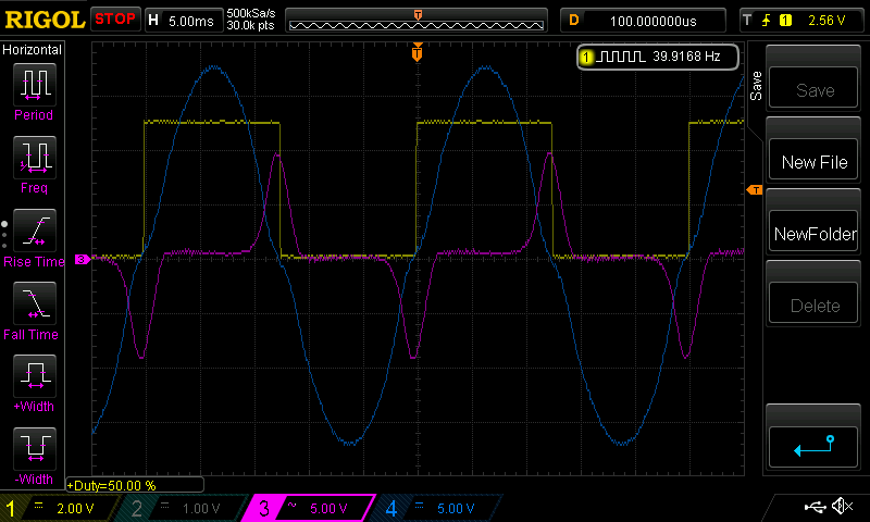 and at 50Hz, very much a different result. The current is much less. 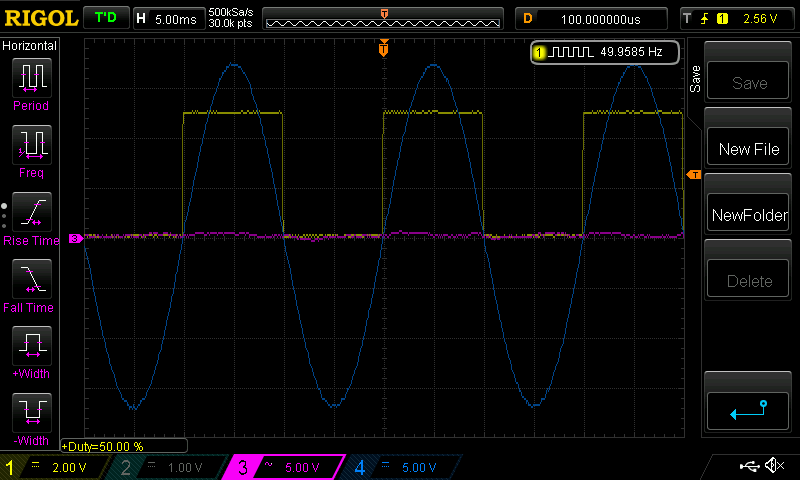 The DC current at 50Hz is 0.26A but at 40 Hz it rises to 0.86A and it is clear to me why it increased. Saturation of the toroid core can be thought of the time when the iron core can no longer accept any more magnetising force from the primary winding and so the primary winding becomes more and more a simple thick wire and less and less an inductor. wronger than a phone book full of wrong phone numbers |
||||
| iannez Newbie Joined: 05/07/2019 Location: ItalyPosts: 23 |
Hi everyone, congratulations for the work done at the level of analysis and implementation on inverters. I wanted to ask Poida if it could be slightly modified the latest software nano_1_v7_no_bessel. if it could output the entire PWM wave from just one OCR1A or OCR1B pin instead of the two pins every 180 degrees, obviously maintaining the same characteristics of the PLL and feedback. this would help me a lot to test without having of an H bridge but using a simple A / B amplifier low voltage. of course I would use a simple R / C filter before entry to the amplifier. I tried to make changes independently thanks to the possibility that Poida offered us by giving us the code, but I didn't succeed, I am probably missing something about the functioning of the code or the timer1 used does not allow this functionality. Thanks in advance! Angelo Edited 2021-01-22 19:38 by iannez Cheers, Angelo |
||||
| nickskethisniks Guru Joined: 17/10/2017 Location: BelgiumPosts: 411 |
Maybe you can use a simple OR-gate? like the 4072 cmos ic? |
||||
