
|
|
Forum Index : Electronics : Various aspects of home brew inverters
| Author | Message | ||||
| poida Guru Joined: 02/02/2017 Location: AustraliaPosts: 1388 |
we have a way / circuit to bypass EG8010 and use Chinese low voltage hardware with arduino and sketch nano1? I assume you need drivers like the ir2110 or similar present on the EG8010 and something that emulates the protections offered by the opamps. I would like to be able to test the sketch with as little hardware as possible on Chinese inverter. yes, here is how I do it. 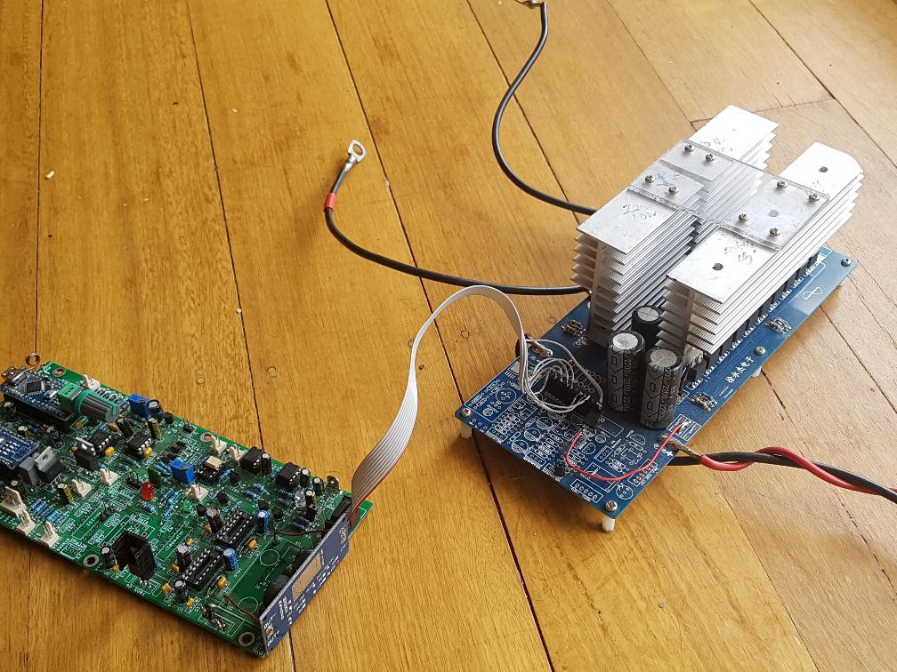 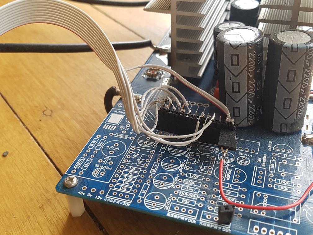 I used a cheap bare PCB I obtained from the supplier and built the minimum, being DC bulk capacitors, MOSFETS, gate drive resistors and diodes. Nothing else at all. The ribbon cable needs to connect 1LO, 1HI, 1VS, 2LO, 2HI, 2VS, DC ground, DC supply (48V in my case) into the nanoverter 10 pin socket. The inverter board is designed for the EG002 module and the pinout is seen on the back of the module PCB. I do not have any over current protection present. The ribbon cable has long conductors that pick up and carry a lot of EMI to both the MOSFET gates as well as back to the IR2148 driver ICs This is not a well designed system. But it is outstanding in the ease of building, cost, and experimentation in my view. This is a low frequency inverter, and so it requires a correctly sized inductor in series with the primary winding of the output transformer. AC voltage feedback is connected to the nanoverter. You can build the bare bones version of the nanoverter. This is the prototype I made to prove concepts prior to nanoverter design. 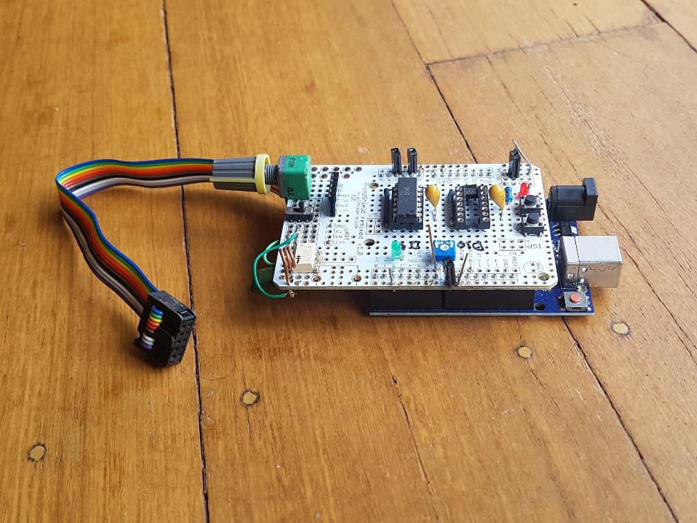 It has only one IR21488 installed but you can see it's not very big. It sits on top of an Arduino Uno. This board was used to develop most of the code including the mains synchronisation. It also can and will run the above inverter power board. You could build a similar small PCB for the gate drive and connect it to the Blue Pill, and then experiment away. wronger than a phone book full of wrong phone numbers |
||||
| poida Guru Joined: 02/02/2017 Location: AustraliaPosts: 1388 |
- why is the high voltage inverter not used in the amateur field? my first answer is to be sure not to handle DC at 310 or more volts. I assume that the sketch nano1 can safely drive through drivers with adequate dead time, a high voltage H bridge. if safety and efficiency are not the problem, what would improve using the output transformer? I am sure others can answer this much better than I can. The transformer type (I call it LF for low frequency) has shown to be easy to build and robust. Peak power levels into 10kW and well beyond are quite common in systems built by people who run their entire houses. When unskilled builders make 10kW power electronics, I think we all want to be exposed to 50V DC only. We can usually safely construct the 240V AC output wiring using common sense and widely available components obtained from nearby hardware stores. The high voltage inverter (or HF) does not need the heavy LF transformer. But it requires a DC supply of the AC output peak voltage. For 240V AC output, that means 340V DC or likely about 20% more than this. I do not like working with 400V DC and I like even less working with 400V DC backed up by large capacitors. In my view, I will never build or attempt to repair a HF inverter. Efficiency of a well built LF inverter can be 95% over a wide range of output power levels. In most cases our builds have the idle power loss to be around 10W. Our builds are from 2kW to 6kW and larger. This is good idle power loss. Other losses are DC resistance through the primary and secondary winding of the transformer. Since we build the transformer, we can limit these losses to very low levels. Usually commercial transformers are designed and build to be near the onset of saturation at their operating frequencies. We can build a transformer that will be far away from any amount of saturation under operation because we can oversize the core and the two winding copper conductor cross sectional areas. Sometimes this is done to nearly humurous degrees. There are also Rds(on) losses in the MOSFETs when they are switched ON. This is not insignificant but it is small compared to the larger loss due to the switching from ON to OFF or OFF to ON the MOSFETs are required to do at 20kHz. These two losses can amount to 100s of Watts and necessitate large heatsinks and good cooling fans. All of the above can be managed easily by system builders of varying degrees of electrical, electronic and mechanical engineering skills. wronger than a phone book full of wrong phone numbers |
||||
| poida Guru Joined: 02/02/2017 Location: AustraliaPosts: 1388 |
i am trying to figure out how to correct the inverter output shape. this without relying only on the voltage peak dictated by the feedback to follow the output voltage on both half-waves (I imagine a half-wave on unipolar EG8010) the idea is to sample the output waveform and compare each sample to the one present in array l[NPWM at the same time of reading. the difference between the comparison gives the value to be given in the OCR1A when it will create the output PWM pulse to correct the output deformation. can my logic be correct? I think there is no value in trying to correct the shape of the AC output voltage. My view is the AC voltage shape will always be something other than a nice and clean sinewave. It will always have harmonics of various frequencies and power levels present that produce something like my street power voltage right now. 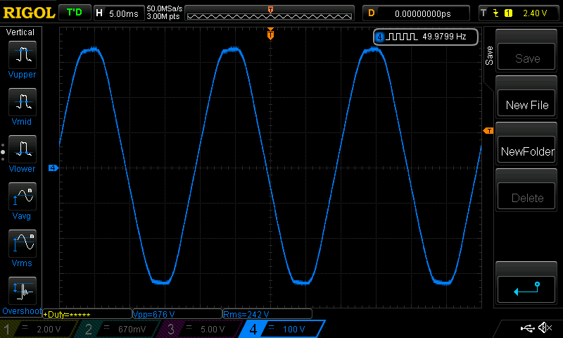 here is a FFT showing the harmonics of it 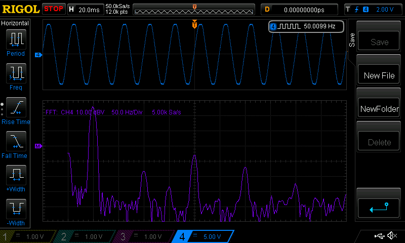 see the strong 250Hz component with -30dbV and the others at 150 and 350Hz These probably flatten the peaks of the waveform. and for comparison, a clean sinewave, again at about 50Hz 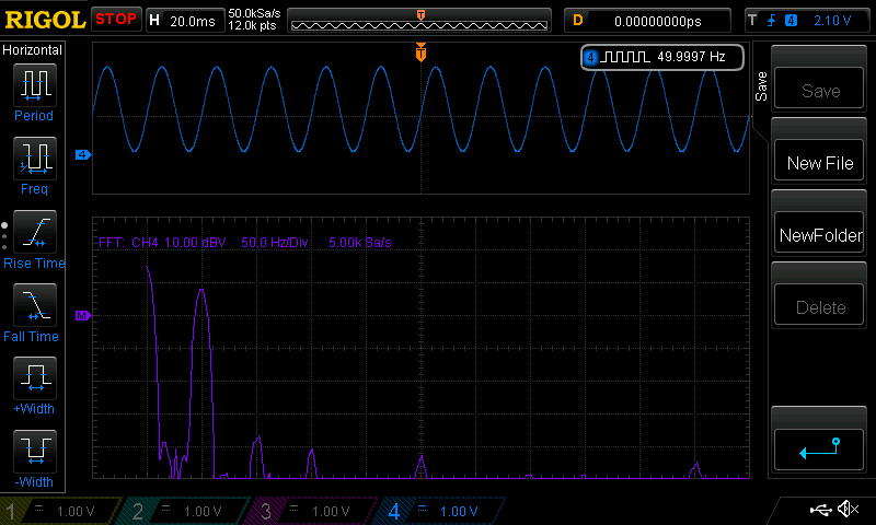 To correct a distorted waveform will require well designed voltage sample systems and closed loop controls. If I was to do this, I would obtain an average error value (in terms of volts not percentage!) over maybe 20 entire waveforms. I would maintain a running average of this, which then provides a time averaged error in volts of the output AC voltage waveform at various angles or waveform positions. I then use that error to correct, hopefully, the distortion. But I don't do this in the nanoverter code. The code samples the AC output voltage, after it is stepped down to 12V, then rectified, then smoothed via a resistor divider. It samples this quantity once per complete 50Hz cycle. The time of this sample is at a zero crossing of the AC output. The voltage measured is DC (after step down, rectification and dividing) and so it will be something like 2.5V. I apply the DC sample of AC output to the PID control loop and correct the magnitude of the PWM waveform accordingly. Again, I see no need to correct waveform distortions that are due to loading of the inverter's output. We try to produce a "clean" sinewave during building of the inverter. This is usually achieved with correct choice of primary inductance, secondary capacitance and toroid build quality. And then we live with the results when we use the inverter. wronger than a phone book full of wrong phone numbers |
||||
| noneyabussiness Guru Joined: 31/07/2017 Location: AustraliaPosts: 506 |
Good answer as always poida why " low frequency " transformer designs are used... simply surge rating are tremendous, the only real limit to surge rating is battery, mosfet, cables, heat buildup... not in that order of course.. Another point too is the fact that you can ac couple them to a " on grid inverter " reducing load on system, increasing efficiency of solar input and any excess power above usage will " flow " backwards and charge your batteries... and can even be regulated with pwm.. " High Frequency " inverters cannot do the above.. I think it works !! |
||||
| iannez Newbie Joined: 05/07/2019 Location: ItalyPosts: 23 |
Good evening everyone, Thanks for your answers! I realized that playing with the 400vdc is not a good thing. I remember that in one of the many jobs done as a boy (electrician) to have taken the 10kv of a transformer for neon. I lost use of my arm for 20 minutes. and my heart was not so happy. I understood that the LF transformer acts as a dam also for any peaks or current draws bidirectional, mitigating based on core type and sizing. naturally also as a filter based on inductance or capacity present before or after. i used all three inverters, but the one LF will be the base like test bench for experiments as you did. excellent Peter, thanks for the support, i checked what i have as hardware: 3 x ir21844 are equal to 2184? I don't think they are the same. and 2 x ir2110 the other components are easily found here and there. however I cannot find the schematic of your breadboard. seen up here: https://www.thebackshed.com/forum/ViewTopic.php?TID=9409&P=13 can you describe the pattern if you still have it somewhere? do the navoverter boards advance to anyone? I read about your THD analysis at this link: https://www.thebackshed.com/forum/ViewTopic.php?TID=9409&P=5#105260 "Time to look at waveform purity. I calculate the THD of this prototype inverter to be about 0.5% (50Hz 70db, 3rd 25db, 4th 25db, 5th 20db, 6th 20db) via the DSO's FFT. Not too bad at all. " great, but the DSO Rigol can give you the distortion percentage too? I ask because within a few months I will have to buy it, it is essential otherwise I have no objective feedback on the changes made and the debugging of the problems. i own this to test distortion. 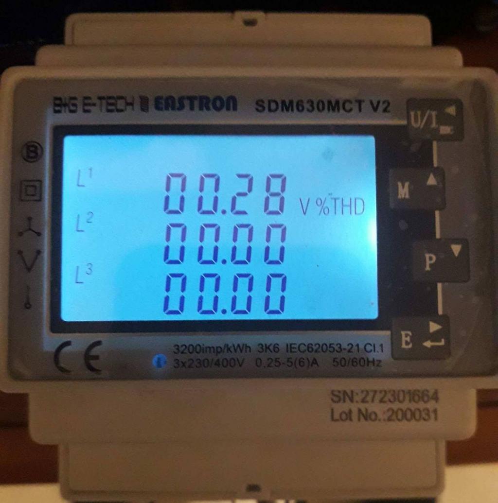 0.28% because I measured at the output of the hifi ps audio conditioner. at the input I have 3-4%. Ciao! A. Cheers, Angelo |
||||
| poida Guru Joined: 02/02/2017 Location: AustraliaPosts: 1388 |
IR21844 have a pin to allow setting dead time. IR2184 do not have this pin so dead time is fixed at 500nS Otherwise they are the same. The Rigol DS1054Z does not have distortion measuring. It would be nice. You saw how I obtained my measurement so there are ways to do this. I will private message you a collection of files that will help. wronger than a phone book full of wrong phone numbers |
||||
| iannez Newbie Joined: 05/07/2019 Location: ItalyPosts: 23 |
tnx Peter! i read  i used those to try to avoid mosfet breakage. I don't worry about the empty load now. See you soon! Ciao! A. Cheers, Angelo |
||||
| poida Guru Joined: 02/02/2017 Location: AustraliaPosts: 1388 |
Part 40: Current sensors and inverter DC peak current We are lucky to have access to Aerosharp grid tie inverters for cheap prices. No matter if they work or not. The parts inside are what we want. Every Aerosharp I have dismantled contains 3 LEM brand current sensors. Usually 2 15 Amp (which can measure +/- 50 Amps actually) and one 6 Amp sensor (good for +/- 25 Amps) They are easy to use. Give it 5V DC supply and all 3 of the sensors will output 2.500V when zero current is flowing through them. Maximum output is about 0.2V for negative max current and about 4.8V for positive max current. Usually the calibration is something like 0.040V/Amp so with the 2.5V max range, this is 2.5 / 0.040 = 62 Amps I frequently increase the measure range of these sensors by using a short shunt to take most of the current and let a small part of it flow through the sensor. Of course the calibration is wrong, so just recalibrate it with the shunt in place. The sensor I used had an extra shunt so it's sensitivity is 0.020V/Amp so it's max current it can measure is now about 125 Amps Today I was wondering what the peak current on the DC input of my victim inverter was when I ran the air compressor. The first test showed the current way exceeded 125 Amps so I needed extra shunt. in the below photo you can see the sensor (Blue) and the 3 shunts. The smallest one is permanently soldered in place, to give 0.020V / Amp I had to add the other two, to bring the sensitivity down to 0.0092V/ Amp This means I can measure 2.5V/0.0092 or 270 Amps 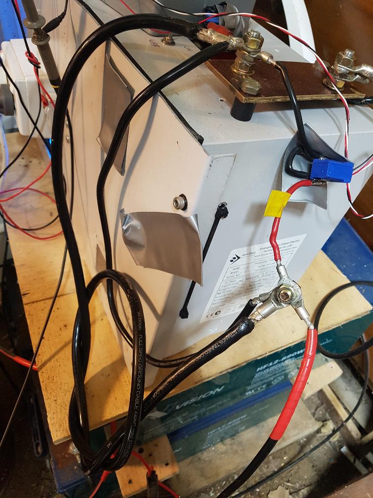 Here is the switch on current for the air compressor: 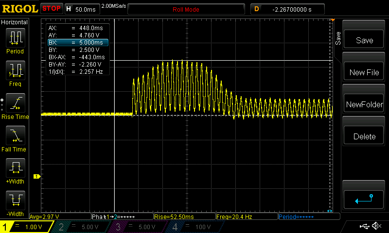 Yellow is DC input current and 1 division = 1V = 108 Amps Peak current is about 2.26 Volts up from the 2.500V zero level. This is 245 Amps. Once the motor settles down (and that only takes about 1/4 of a second) the current drops to something more reasonable. An interesting feature of the motor running is the negative current part of the waveform. It is an AC induction motor after all so it has some reactive power component. This is what reactive power means - there is an exchange of current between the source (the inverter) and the load (the motor) and this exchange happens with positive and negative current. I thought it best to see if I could put a larger load on the inverter. So I switched on the 2500W 10 Litre hot water urn first, then ran the compressor. The Urn takes about 56 Amps DC from the supply. Adding this to 245 Amps is about 300 Amps. Unfortunately the inverter popped the DC breaker. OR was that fortunate? Anyway, it survived fine. wronger than a phone book full of wrong phone numbers |
||||
| poida Guru Joined: 02/02/2017 Location: AustraliaPosts: 1388 |
Some numbers on the above 245 Amps at about 47V. If you notice, the waveform is sine but the frequency is 100Hz. The peak current is at both the positive and the negative peak of the 50Hz output. Peak power during motor start is 245 x 47 = 11.5 kW Wow. In producing the sine wave output, current flows through (say) the low side FETS of VS1 which is pulled down to ground and the high side FETS of VS2 during PWM. If for instance maximum voltage requires a PWM of width 80% that means the high side FETS of VS2 are delivering 11.5 kW when only switched on for 80% of the maximum time. So the current through those FETS is 11.5 / 0.8 = 14.4 kW at waveform peak current. The powerboard in this inverter is a Madness 6kW totem pole type, with 3 FETS fitted on each of the 4 legs. This means 14.4 kW is passing through 3 FETS on the highside and 3 FETS on the other output low side. Is this a reasonable result? 14.4 kW at 47 Volts is 306 Amps. There are 3 FETS so each FET handles 103 Amps. The HY4008 specs give us something called Safe Operation Area which is showing how much power (or volts x amps) is OK for different pulse widths. here it is. The two scales are log scales, you might not be used to these. I marked a Red dot where 47V and 100 Amps is. 10 ms pulse width is shorter than the pulse widths used in the 20kHz nanoverter. 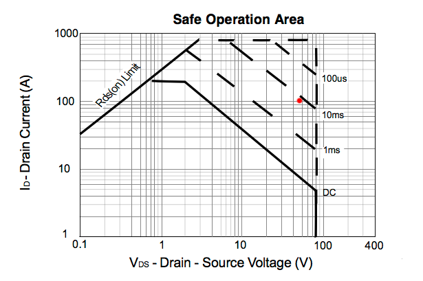 looking at the above I think I am driving the HY4008 about as hard as it's possible to go without fireworks. Could anyone here maybe have a look at my argument and confirm or shoot down in flames as required? I am not an E.E. wronger than a phone book full of wrong phone numbers |
||||
| Warpspeed Guru Joined: 09/08/2007 Location: AustraliaPosts: 4406 |
Safe operating area is a thermal limit of conduction loss only. Ten milliseconds on, and then a cool down period significantly longer than 10mS. Its switching on and off at 20Khz+ so there will be switching losses on top of conduction losses, and you cannot be sure that the current shares equally between the three mosfets. But I think you might be getting pretty close to the limit, but difficult to know where the cliff edge of absolute ultimate doom precisely is. Cheers, �Tony. |
||||
Revlac Guru Joined: 31/12/2016 Location: AustraliaPosts: 961 |
Interesting, might have to try this later, I tried to measure this with a clamp meter with a large induction motor, starting was 137Amp, perhaps this was just an average over 2 seconds. Cheers Aaron Off The Grid |
||||
| Warpspeed Guru Joined: 09/08/2007 Location: AustraliaPosts: 4406 |
Large induction motors can be real inverter killers. Cheers, �Tony. |
||||
| noneyabussiness Guru Joined: 31/07/2017 Location: AustraliaPosts: 506 |
hey poida, got a bit of time at the moment to revisit this project... just a question, if i set up a " master " clock with another arduino , putting out 50hz square wave, could i sync successive nanoverters to it?? rather than trying to sync 240v?? what do you think?? I think it works !! |
||||
| poida Guru Joined: 02/02/2017 Location: AustraliaPosts: 1388 |
I think it would work really well. One Nano or something to produce a 50 Hz clock All the inverters to take this as the sync input. I could modify the code to first get a good sync then run the soft start when the inverter run command signal goes high. Bad things will happen if one looses sync but a momentary loss of the sync pulse would mean a slow drift out of phase. Slow being maybe 1 degree error per second. When testing, please setup a GoPro and record it all. We like a good fireworks show. wronger than a phone book full of wrong phone numbers |
||||
| poida Guru Joined: 02/02/2017 Location: AustraliaPosts: 1388 |
I have improved the nano/picoverter firmware, making the PWM pulsetrain perfectly symmetrical about the zero crossing points. The results are good. (I don't know why I could not get to this point before. Maybe I needed a couple of years away from the problem.) This is the gate drive for V1 and V2 1/2 bridge drives. In the past there was always a bit extra pulses just after zero crossing. I have not tested this on a real live inverter yet so there could be a nasty surprise but I doubt it. 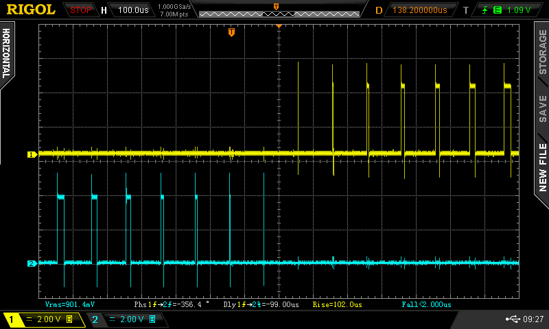 to get this two areas of the code needs to be changed. First, I needed to make the 1/2 sine wave lookup table finish exactly at Pi radians. It is now: void setup() { int i; float t,u; for(t=0.0,i=0; i < NPWM; i++,t += 3.14159/ (float) (NPWM-1)) { u = 65535.0 * sin(t); // 1/2 wave sine lookup table, scaled to (16 bits - 1) l[i] = (int)u; } ... Note the small change to the loop. the other change was to the main interrupt loop, that produces the inverter's PWM sine wave // // 20Khz SPWM, code has only 50uS to run, takes about 10uS // ISR(TIMER1_OVF_vect) { long c; if (pcount == 0) if (v1low == 1) // if first 1/2 wave.. { TCCR1A = _BV(COM1B1) | _BV(WGM11); // config output compare to suit } else { TCCR1A = _BV(COM1A1) | _BV(WGM11); // config O.C. to suit } c = (l[pcount] * vpwr) >> 16; // scale sine wave by vpwr, 32 bit integer calcs. 16 bit shift fastest of all if (v1low == 1) // alternate between 2 output compare pins. Get a full 50Hz waveform { OCR1B = c; // was c 1/2 out this pin } else { OCR1A = c; // and then 1/2 out this pin. } pcount ++; if(pcount >= NPWM) // pcount will = NPWM, at each 1/2 wave, at the start { pcount = 0; // reset counter uf=1; // enable one PID control loop execution, in loop() if (v1low == 1) // if first 1/2 wave.. { v1low = 0; // toggle to 2nd half wave sbi(PORTD,7); //DSO pulse } else { v1low = 1; // toggle to 1st half wave cbi(PORTD,7); } } The changes were 2 fold. One was to time the changeover of D9 to D10 PWM at exactly the best time which is before I write the new PWM width for pulse number 0 for a train of pulses numbering from 0 to NPWM - 1 The next thing was to do this changeover before I wrote the new PWM width. The sync pulse out D7 is now 2 PWM pulses early but the pulse train is now symmetrical, probably to the nearest clock cycle. wronger than a phone book full of wrong phone numbers |
||||
| noneyabussiness Guru Joined: 31/07/2017 Location: AustraliaPosts: 506 |
awesome, still gathering everything up.. but looking forward to having a play with this... I think it works !! |
||||
| poida Guru Joined: 02/02/2017 Location: AustraliaPosts: 1388 |
Wiseguy, please have a look at this post I made In The Wrong Thread (what a wombat..) You can see it tested well and so I will incorporate it into the nanoverter and picoverter code. Here is the picoverter code I used. pico_2_heavy_filter_bv_better_stop_prefect_symmetry.zip This is similar to the nano2 firmware, but without any sync code. It will work whether there is a serial LCD connected or not. wronger than a phone book full of wrong phone numbers |
||||
| wiseguy Guru Joined: 21/06/2018 Location: AustraliaPosts: 994 |
Thanks Peter, I had already found/seen and commented on it. Is the pico code essentially pin compatible with the nano - I dont use sync so if it is compatible, I would like to try it out. If at first you dont succeed, I suggest you avoid sky diving.... Cheers Mike |
||||
| poida Guru Joined: 02/02/2017 Location: AustraliaPosts: 1388 |
The picoverter code is very similar to the nano1_v7 or whatever. D8 pin is the run/stop command D9, D10 are PWM outputs. A0 is Vfb I made a cut down version without LCD support, no temperature sensors, no LV cutoff it just runs the inverter code. here it is pico_2_mikes_better_stop_prefect_symmetry.zip wronger than a phone book full of wrong phone numbers |
||||
