
|
|
Forum Index : Windmills : Diodes on star centre connection
| Author | Message | ||||
| Warpspeed Guru Joined: 09/08/2007 Location: AustraliaPosts: 4406 |
Yes, you get slightly more voltage than in star, but also slightly less maximum theoretical current capacity. It does put out a nice clean rectified dc voltage though. But at very low wind speeds we cannot load the alternator to anything like its full current capacity anyway, without stalling the blades. The driving torque to do it is just not there, so its not a practical limitation. Its about the best we can do for max dc voltage at low rpm with just an alternator and some diodes. The previously suggested mosfet switching scheme should work to give a hazard free changeover, but I have not actually tested this myself. Isolated gate drive power could be provided (initially for testing) from a couple of 9v batteries. Cheers, �Tony. |
||||
DaveP68 Senior Member Joined: 25/11/2014 Location: New ZealandPosts: 292 |
Isolated gate drive can be achieved using small high frequency transformers driven by low power CMOS gates. The output of which can be rectified to provide full gate drive voltage to the MOSFET's. Have them by the hundreds as that was the technique used by F&P to drive the high side MOSFET's on the motor control module boards. Here is a photo of one. The current drawn at very low wind speeds is of no concern if it's being feed into a battery system. This is due to the driving torque of the shaft providing a natural limit on this anyway. This is done by getting the cut in speed voltage correct in the first place and will only allow the current to flow proportional to the power provided from the shaft. The tricky part will be the switching pint going from series to parallel configuration without going to far outside the optimum TSP of the blades. I can work this out as Know the exact electrical characteristics of any F&P stator. This would also involve making sure the stator doesn't go to close to saturation before switching over. MPPT sorts this out through a mathematical algorithm that hunts for the peak power output for a given RPM/TSR. Hence the complex electronics required. There are realities if you do not accept, will lead to frustration because you will be spending time on wrong assumptions and the results cannot follow! The Dunning Kruger Effect :) |
||||
| Warpspeed Guru Joined: 09/08/2007 Location: AustraliaPosts: 4406 |
You might like to take a look at an International Rectifier PVI-N chip. http://pdf.datasheetcatalog.com/datasheet/irf/pvin.pdf These are a fairly unique opto isolator, in that the LED illuminates a small photovoltaic "internal mini solar panel" capable of turning on a completely isolated mosfet gate directly. They are not ultra fast switching, about 100uS on and off, but ideal for something like this as it really simplifies things. Its what the expensive high power mosfet dc solid state relays modules use, although the bare opto chip by itself is not expensive. I only suggested using the battery for a quick bench test of the concept. I think you might get much closer to how a real battery system behaves if you build a suitably powerful shunt voltage regulator to use as a load, to feed dc power into, and use that instead of a plain resistive load to test all of this. One last idea. Connecting three bridges in series produces exactly twice the dc output voltage of a delta connection, as you have already verified. That could be further increased by connecting an electrolytic directly across the dc output of each individual bridge. Depending on the value of the electrolytic, the rpm, and the loading, it should be possible to get from at least double, to something almost approaching three times the usual delta dc voltage. Again just another untried idea that should work. But as its pretty easy to do, it must be worth a try. Cheers, �Tony. |
||||
| DaveP68 Senior Member Joined: 25/11/2014 Location: New ZealandPosts: 292 |
Thanks for the heads up on that International Rectifier PVI-N chip but I'll stick to what I've got as they are free vs $10.00 per chip. One big advantage in using them though is they keep the eternal part count low. Have already made you aware of the fully controllable load that can simulate a battery. It's adjustable from 40 VDC up to 460 VDC, but need to make a modification for it to take more than 5 Amps up to say 20 Amps. This way can set it to 48 V or up to 59 V to simulate different charge states of a battery. There are realities if you do not accept, will lead to frustration because you will be spending time on wrong assumptions and the results cannot follow! The Dunning Kruger Effect :) |
||||
| Warpspeed Guru Joined: 09/08/2007 Location: AustraliaPosts: 4406 |
I agree, using stuff you already have always beats buying something new. But others reading this thread may be starting out with nothing suitable readily at hand, and the PVI chips are a rather interesting component of which I only recently became aware. They may be useful for quite a few other "Back Shed" type projects. I forgot you had the programmable load. Very handy thing to have. Cheers, �Tony. |
||||
| DaveP68 Senior Member Joined: 25/11/2014 Location: New ZealandPosts: 292 |
Good point re the PVI chips and that's why I said they keep the component count down. Yes they are the device of choice for those who take an interest. The little transformers I'll end up using do require a few more parts make them work plus are now hard to find as F&P stopped using them 21 years ago. There are realities if you do not accept, will lead to frustration because you will be spending time on wrong assumptions and the results cannot follow! The Dunning Kruger Effect :) |
||||
| Warpspeed Guru Joined: 09/08/2007 Location: AustraliaPosts: 4406 |
Those little transformers look to me like a standard common mode choke. If you can measure the inductance, it would probably be fairly easy to find a direct equivalent.  Cheers, �Tony. |
||||
| DaveP68 Senior Member Joined: 25/11/2014 Location: New ZealandPosts: 292 |
I'll have to get back to you on that as the 'common mode choke' as you put it that I've got in big numbers just work from my perspective. Not much incentive for me to find out it's electrical characteristics. Will let you know the results though when I get the switching circuit that you proposed up and running. There are realities if you do not accept, will lead to frustration because you will be spending time on wrong assumptions and the results cannot follow! The Dunning Kruger Effect :) |
||||
| Warpspeed Guru Joined: 09/08/2007 Location: AustraliaPosts: 4406 |
O/k fine, its just that you said they were now hard to find. If you already have quite a few salvaged from old circuit boards, then no problem. It makes sense for F&P to have used something like that as they are cheap and pretty readily available. They are made and sold to be used as common mode chokes, but they can also be used as a 1:1 high frequency transformer with pretty good voltage isolation. Cheers, �Tony. |
||||
| DaveP68 Senior Member Joined: 25/11/2014 Location: New ZealandPosts: 292 |
I think the device of choice is still the PVI chips as they keep the component count down and that is what I was trying to promote. Mean while got a heap these parts salvaged from old circuit boards so will put them to use to at least prove the concept of the proposed switching circuit. The final production/working unit that we can be published on here will probably use the PVI chips to keep the circuitry easier to construct in our the back sheds. There are realities if you do not accept, will lead to frustration because you will be spending time on wrong assumptions and the results cannot follow! The Dunning Kruger Effect :) |
||||
oztules Guru Joined: 26/07/2007 Location: AustraliaPosts: 1686 |
Davep68, I tried to play with my f&p, but i had wired it for low voltage high torque pump application on a mono pump... which works very well oddly enough..... anyway, I decided to pull it off and put it in the lathe, expecting maybe 15 amps or so, and at fairly low rpm... maybe 300 perhaps. I don't know what stator it is, and have not even bothered to count the poles after the modifications some time back... memory is poor and pole count matters not any more, but you will probably want to know what it is... the pic follows. I fired it up into some 220 amp 6v batteries, and this is what happened. here is the stator with feeble wiring. 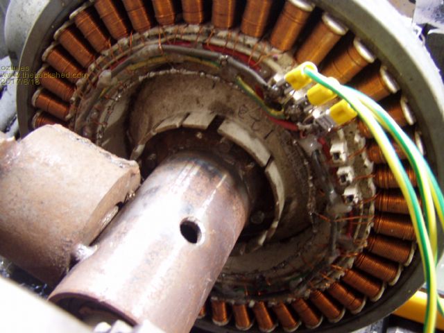 It needed over 500 rpm to get to 20 amps, and made it to 40 amps or more...on the 750 setting...... then the belts slipped.... the pic caught it at around 38amps. 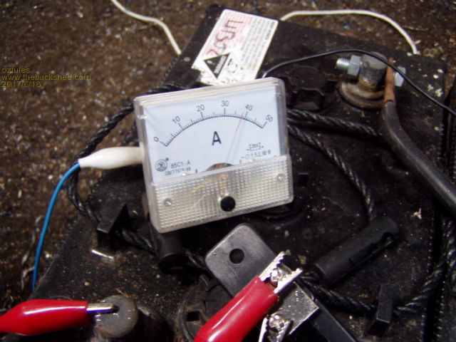 So it was clear the driving device would not go much further. I slipped a phase out to get an idea of what may happen when i connected the star point.... it went from 20 amps to 25, I was pulling up near 1000 rpm, belts were not happy, so I can say that in single phase , when you add the star point diodes as well, there is a marked increase, but i will need to do something better with the driver before i can discount the three phase hook up. It seems to be getting current limited after 750rpm, so the delta would not kick in until well over 1000rpm I suspect. Anyway thats as far as I got today, and proved nothing, so at this stage i can't say the star delta diode system works at all ... never mind well, but the theory seems good so it needs better power inputs. Very surprised at the 40 amps... didn't expect that much , and it would appear that a 5hp IC engine coupled to it would make a nice cheap little 2kw 48v charger ... even in just star. I noticed the iron losses are very small too... another good thing. EDIT..... on reflection, I should have tried it on 6v....dammit, i've put it away for the day .... maybe tomorrow... .........oztules Village idiot...or... just another hack out of his depth |
||||
| DaveP68 Senior Member Joined: 25/11/2014 Location: New ZealandPosts: 292 |
Hi oztules The stator looks like an 80s 14x 1p star. Did you feed it into 2x 6 V batteries in series? That would make the battery terminal volts something around 14-15 VDC depending on how charged the batteries were. The optimum current from that set up is 28.28 Amps at what ever volts/RPM level you want to run at. The maximum current is 40 Apms which is 1.414 x that optimum current for 80s 14x 1p star. Interesting result removing 1 phase and noting a jump from 20 to 25 amps. RPM was very high though. These stators are very predictable once you get to know them in their star/delta nodes. There are realities if you do not accept, will lead to frustration because you will be spending time on wrong assumptions and the results cannot follow! The Dunning Kruger Effect :) |
||||
| oztules Guru Joined: 26/07/2007 Location: AustraliaPosts: 1686 |
You know your stuff Dave. Yes that was nominal 12v ( 2x6v )... don't know why I did not think of just paralleling the batts and run lower rpm to test the theory.... getting too old perhaps. "Interesting result removing 1 phase and noting a jump from 20 to 25 amps. RPM was very high though."..... yes this makes no sense when you draw it out unless the star delta switching is working as described.... but then why not in 3 phase... will find out today.... is it just lack of rpm where the losses in the star legs were not high enough yet to allow the delta circuit to contribute???/ I'm thinking so, although not a shred of evidence to support me as yet. "The optimum current from that set up is 28.28 Amps at what ever volts/RPM level you want to run at. The maximum current is 40 Apms which is 1.414 x that optimum current for 80s 14x 1p star." ... not sure I understand this... I would have expected optimim current in a reactance protected system to be flat stick, as no damage should follow whatever loading was presented. The root 2 is more a peak/rms thing for me. the delta/star relationship is more a 1.7 x delta or star..... or are you thinking of restive I^2R loss in the wire?... Not being an F&P player, I am not sure what you mean by optimal I guess is what I am saying. I can drive it into a direct short today too, that will show things up in the rpm range I have some torque in. Hopefully I can put this to rest one way or another. I will study your charts when i can find them to see if the engine generator is worth pursuing, 2kw for peanuts is worth looking at.... maybe 7p delta will work better... will look for your figures. EDIT: found this on your other thread "Next test was with a 80s 42 pole stator wired 14x 1p Star got 1575 W at 1870 RPM with other readings of 57.4 VDC at 27.44 Apms."... and i don't understand it..... Why did I get 40 amps in the same sort of config.... did you not push it far enough?, or I am missing something else.... ie what happened at 3600rpm? ........oztules Village idiot...or... just another hack out of his depth |
||||
| oztules Guru Joined: 26/07/2007 Location: AustraliaPosts: 1686 |
It's official.... don't know what I am talking about. The best I can do is 45 amps on the dot. As I was only interested in the current, a short circuit was sufficient to test this setup. The leads are skinny, so it was nowhere near a real short I guess. Result is NO DISCERNIBLE CHANGE with the extra diodes in place it was 45 amps versus 45 amps.. nothing... nix.. I can't see why this is the case... but it is.. Dave was right. Still amused that 45amps is possible before full back mmf cancels the driving field. At higher rpm it will also get inductive reactance due to the high frequency... but it takes very little rpm to get 45 amps at short circuit, so at least I can say the the frequency induced reactance is not why current limiting is occurring, but in fact back mmf is responsible for the most part at these low frequencies. Herbnz was right, flux was less right.... thats it for the synchronous impedance anyway. I can see a generator being built soon using the 80s stator. 40 amps is plenty for a little petrol motor. ........oztules Village idiot...or... just another hack out of his depth |
||||
| DaveP68 Senior Member Joined: 25/11/2014 Location: New ZealandPosts: 292 |
Hi oztules The optimum current refers to the most efficient power extraction at that RPM level. So in my example that turned out to be 1575 W at 1870 RPM with other readings of 57.4 VDC at 27.44 Apms. The current reading was over an approximated shunt, close but not as accurate so reading could have been as much as an amp too low. Your maximum of 45 Amps is the limit again my one didn't quite get that high but I would have only been about 3 amps lower. I also didn't test my 80s 14x 1p at a very high RPM to reach 40 plus amps so my 1.414 times was just a projection. I your case you got about 1.5 times optimum current. Some rotor caps can have less magnetism especially if there was a motor short on at the time of the washing machine failing which can generate an opposing field. Will need to repeat my test to confirm your peak reading of 45 Amps with a different rotor cap. This time will do the new test at 24 VDC at around the same RPM level to check what my maximum current will be. The continuous RPM limit of the rotor caps is 3000 RPM and they fly apart immediately at 5000 RPM!! They will do 3600 RPM for a short duration but if it has a defect could let go at 3600 RPM under load conditions, so be careful... There are realities if you do not accept, will lead to frustration because you will be spending time on wrong assumptions and the results cannot follow! The Dunning Kruger Effect :) |
||||
| oztules Guru Joined: 26/07/2007 Location: AustraliaPosts: 1686 |
Thanks for the warning, didn't realise they were a bit delicate. It comes down to amp turns for a given airgap and magnet arrangement. We either use less turns per phase to get the current up, or use better magnets. One of the endearing things of the F&P is the current limiting, so more magnet is not my first preference...more rpm would have been...... 45 amps at high rpm may be more difficult, as the synchronous impedance will then incorporate much more inductive reactance as the frequency rises, that may be why you have not seen 45amps perhaps. Mine was shortcircuit ( but for skinny leads), so the rpm was very modest to get the current up, so inductive reactance was very low i suspect.... see how it goes ...........oztules Village idiot...or... just another hack out of his depth |
||||
| DaveP68 Senior Member Joined: 25/11/2014 Location: New ZealandPosts: 292 |
Hi oztules This explains why I was maxing out at 40 Amps and you got 45 Amps. To date haven't done any high RPM short circuit testing, as didn't see the point for a net Zero output result. So did a high RPM short circuit tests and the maximum current I got was 44.25 Amps. My shunt was proving to be accurate after all. So at high RPM my figure of 40 Amps into a practical load still stands as an upper limit, but not quite maximum. Did try a few different rotor caps to check how close they were at maximum current. Most maxed out around 44 amps with readings of between 43.4 and 44.25 Apms. Also another factor is the variation from stator to stator which is why your stator could be 0.75 Amps higher again than mine. This is of course conditional on your 45 Amp reading being very accurate. There are realities if you do not accept, will lead to frustration because you will be spending time on wrong assumptions and the results cannot follow! The Dunning Kruger Effect :) |
||||
| oztules Guru Joined: 26/07/2007 Location: AustraliaPosts: 1686 |
Accuracy was of no concern to me in those tests, the only thing I was interested in was the theory, and if it was to hold water... which I have not been able to prove in any way shape or form. I only wanted to see change, and i didn't much care what the empirical figures actually represented... in this case I reckon it was pretty close to what it purported to show. So the short circuit figure, while interesting, is of no real use, other than to explore the losses in the stator.....Nice to see you got the same magnitude though. I am intent on making the IC genny version, so will heed your advise, and perhaps band the outside perimeter. I think that one of these connected to a <200 dollar electric start motor on ebay will be pretty nice to use... simple and idiot proof perhaps. .........oztules Village idiot...or... just another hack out of his depth |
||||
| DaveP68 Senior Member Joined: 25/11/2014 Location: New ZealandPosts: 292 |
Hi oztules Can't help myself on the accuracy part of my readings, probably to do with working in aviation in the past and having to follow strict rules or you could be killed. Will try replicating the test you did by removing a phase to observe the jump in current from 20 25 amps you noticed. Have an idea why but want to check it out for myself. If you can get hold of a copper 36 pole stator with a black rotor cap they will output more power for the same RPM or same power at lower RPM by a factor of 40%. You can of course stick with your 80s 14x 1p star that's already working very well though. There are realities if you do not accept, will lead to frustration because you will be spending time on wrong assumptions and the results cannot follow! The Dunning Kruger Effect :) |
||||
| DaveP68 Senior Member Joined: 25/11/2014 Location: New ZealandPosts: 292 |
Hi Tony Know it's been a year since this topic had it's last post, but have done some more testing and got some interesting results. Connected an 80's stator up in normal Delta mode and run it up to 646 RPM power output was 560 W 160 VDC at 3.5 Amps. The input power measured by my inline torque meter came to 683 W (Torque reading 10.1 Nm). That is 82% efficiency. Then took the same stator and wired out each group of 14x coils to their own rectifiers as per your circuit at the top with their DC outputs all in parallel. Run another test at 673 RPM into the same load and got a power output of 480 W 160 VDC at 3 Amps. The input power was 649 W (Torque reading 9.2 Nm). That is 74% efficiency. Goes to show that was seems like a great idea on paper can have unintended outcomes. An 8% lower operating efficiency is a big drop. I'm still interested in exploring a form of switch system using a delta configuration and just use different wiring setups to get the desired outcome. Cheers David There are realities if you do not accept, will lead to frustration because you will be spending time on wrong assumptions and the results cannot follow! The Dunning Kruger Effect :) |
||||
