I now have a couple of photos of my board's protection.
Here is part 2:
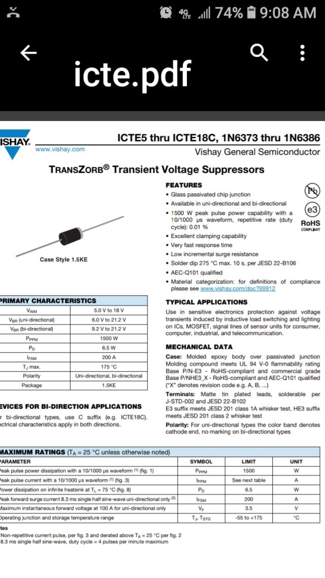
Obtain some 15V TVS devices. I think of these as good, strong, fast acting
zener diodes. They permit up to 18V to pass in one way, and very quickly clamping any voltage over this. And when voltage is flowing the other way, they are fast diodes, conducting the current, but with a small voltage drop of about 0.4V at the working currents.
RS part no. 815-2578
Vishay ICTE15-E3/54, Uni-Directional TVS Diode, 1500W, 2-Pin 1.5KE
AUD $0.92 each in a pack of 10
We want to protect the gate drive outputs of the IR2110 chips.
The manufacturer states all outputs must never go below about -0.3V compared with
ground or the high side "ground" which is the high side MOSFET's source pin.
Additionally, the specs say to never exceed 20V.
These 15V TVS diodes are about right for the job. Read the specs.
We only need 4, and we connect them near the MOSFETs, since that is where the potentially damaging voltages are generated. We connect each gate drive output to the corresponding MOSFET source pin.
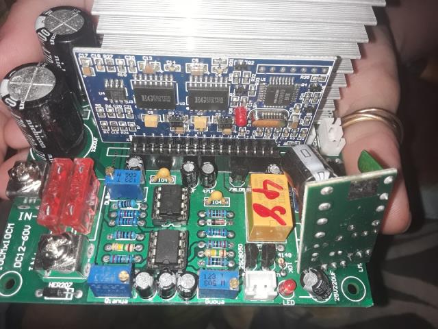
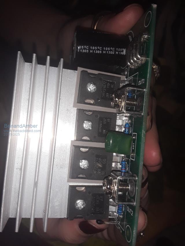
In the case of my board shown below, I have 3 MOSFETS in parallel for each of the 4 legs of the full bridge. So I only need to do each leg of the full bridge, not all 12 MOSFETS.
all 4 TVS in place:
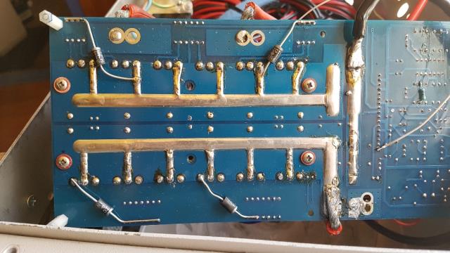
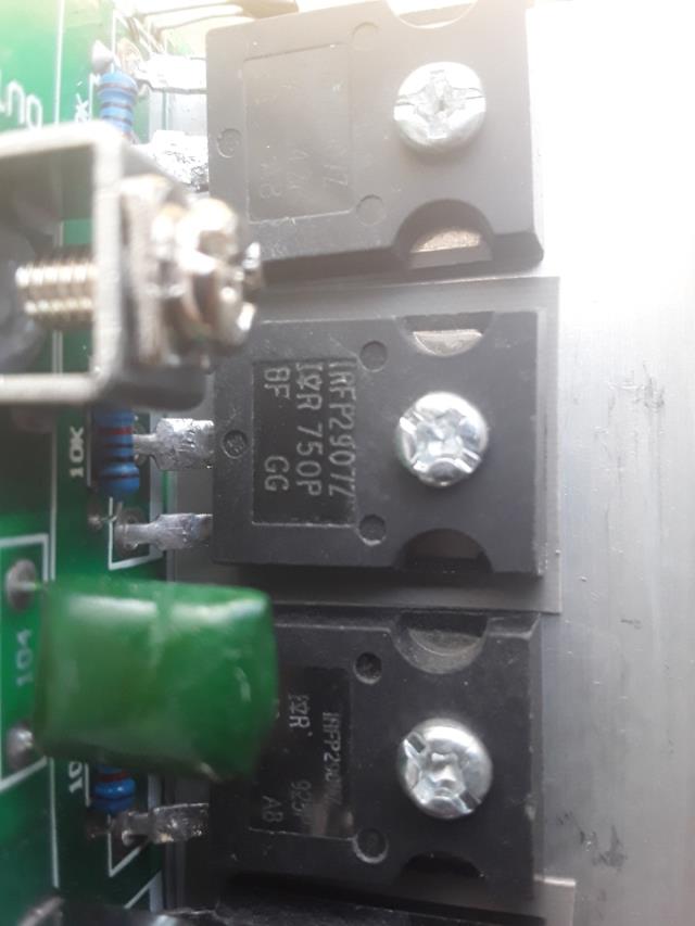
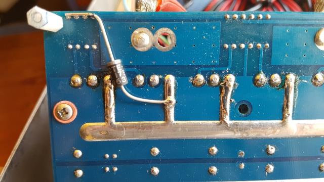
a detail shot of one, showing polarity. Take care to fit these the correct way.
wronger than a phone book full of wrong phone numbers