  Page 2 of 2 Page 2 of 2 |
Posted: 01:44pm
24 Apr 2020
 Copy link to clipboard Copy link to clipboard |
noneyabussiness
Guru

|
|
|
Ok... sorry for late reply... yes out of the box it was at " full " current 1200watts.. once i put the extra 3 turns ( trial and error , started with 2 etc) it will happily max out now at about 3.5kw , i usually only have it under 2kw as i don't usually need more than that...
The 3 ive modded for this use have all been full bridge, igbt transformer driver , current controlled ( no voltage control that i can see) , funnily enough only half wave rectified on the secondary, with 3-4 high powered diodes in series on same heatsink.
What i can see in the pics you have provided look very similar, the big green toroid is the transformer that needs the extra turns, you will have to work out the secondary, follow it to output diodes..each turn makes a significant difference so i would start with 2 and go from there..
Once sorted they are very tough...
I think it works !! |
| |
Posted: 01:49pm
24 Apr 2020
Copy link to clipboard |
noneyabussiness
Guru
|
|
|
Oh and the rating, take it with a grain of salt.. 200amp for short bursts, but it gets warm putting 3kw in for hours on end, so doubt it could 9.6kw for extended periods of time.. but for a 100 bucks it is a tough charger once setup..
Honestly i would like to up the input cable even for 3kw, gets warm.. damnt, hasn't missed a beat but you mob got me worried now..
I think it works !! |
| |
Thanks Noneya. Mike there was another two connections, total of 6 ends, so 3 coils. OK so the common connection on the right is the one that goes to the negative output on the welder. That common connection has continuity to each of the other two ends. 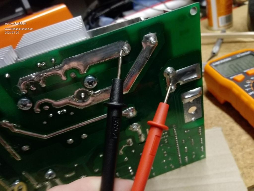 Those two ends go to the left and have a diode on each side of a heatsink. 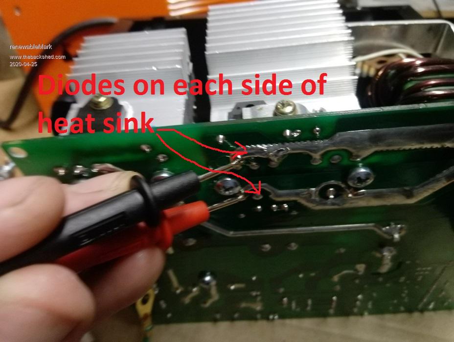 
Cheers Caveman Mark Off grid eastern Melb |
| |
Ok, pull out the two ends going to the diodes and add 2 more turns to them and terminate the new ends in the same holes - wont matter if they cross over (swap sides) in the process it is a full wave rectifier. Show Tony how its done �  PS if it goes bang my previous posts will self destruct..... Edited 2020-04-25 08:56 by wiseguy
If at first you dont succeed, I suggest you avoid sky diving.... Cheers Mike |
| |
Posted: 11:03pm
24 Apr 2020
Copy link to clipboard |
noneyabussiness
Guru
|
|
|
Check open circuit voltage, all ones ive done are around the 90v mark, to get the most out of them... they are current controlled so don't worry about the high OC voltage...
I think it works !! |
| |
Posted: 11:04pm
24 Apr 2020
Copy link to clipboard |
noneyabussiness
Guru
|
|
|
If i get a chance today, ill get some photos of mine if it will help...
I think it works !! |
| |
Posted: 11:26pm
24 Apr 2020
Copy link to clipboard |
Warpspeed
Guru
|
|
|
All sounds quite reasonable.
I think I will just watch the fun from a safe distance.
Cheers, �Tony. |
| |
|
Thanks guys,
I'm only getting 62v OC.
Out of the box it only provides 1.9A so it appears to be made with a much lower voltage to your I-max one.
I need a little welder anyway, so it may be wise to just put this back together and buy the same I-max one and copy your proven mods.
Cheers Caveman Mark
Off grid eastern Melb |
| |
Did a bit of tracing back to see where things go. 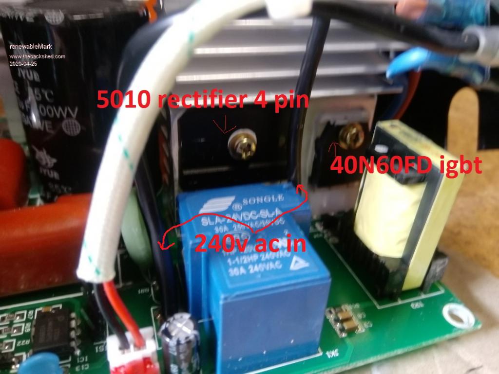 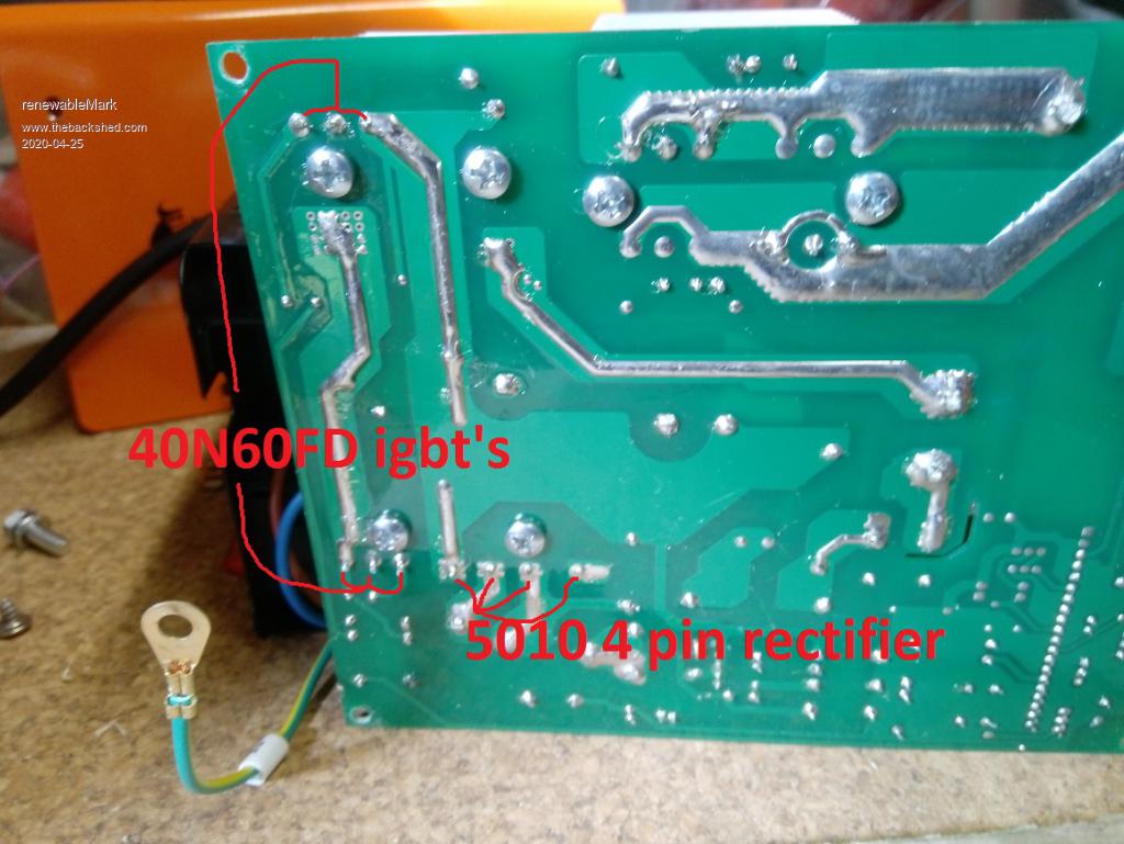 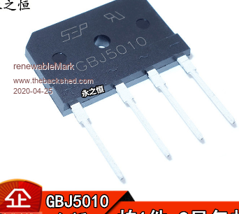 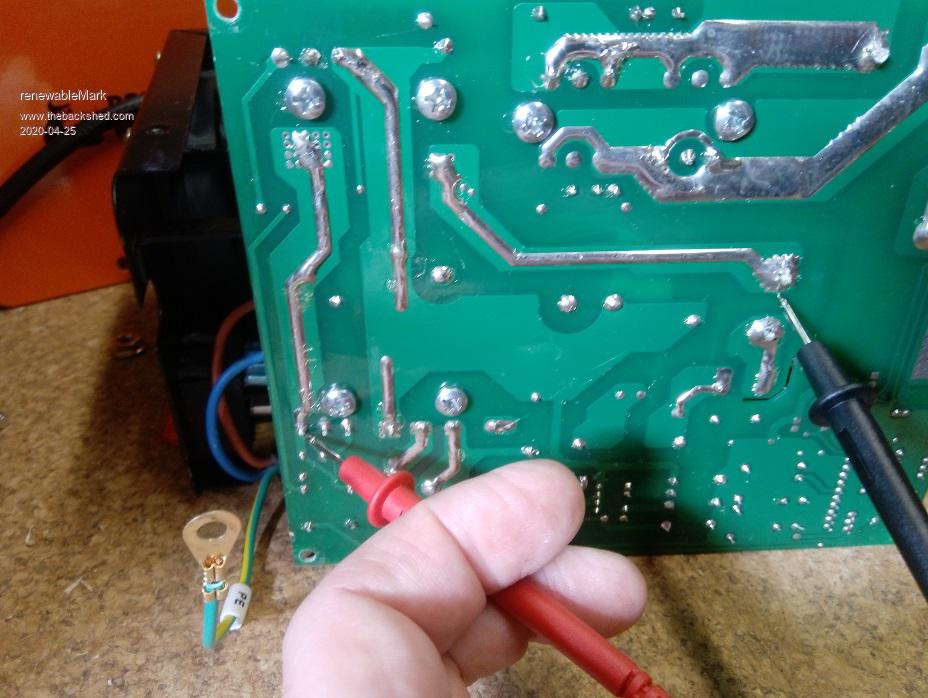 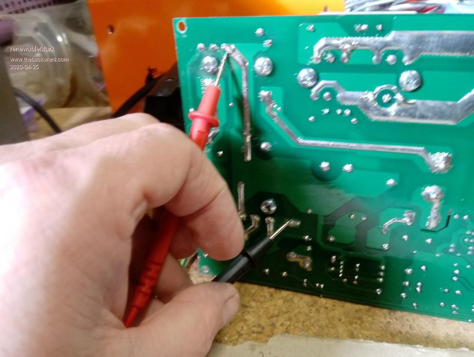 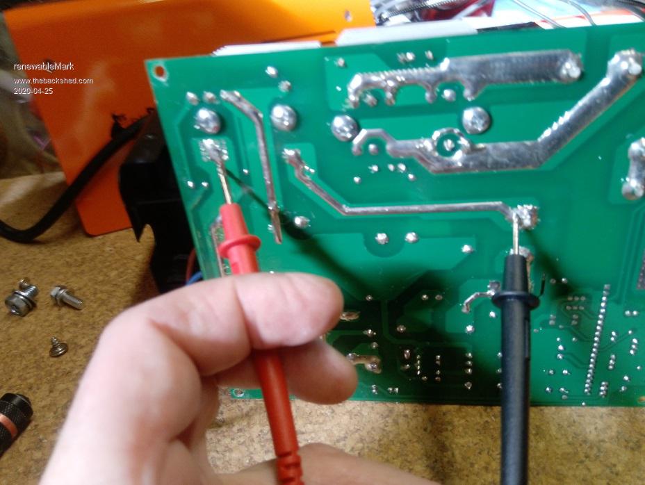 Where I'm holding the probes there is continuity. So it looks like the 5010 rectifies the 240v and the IGBT's control the feed to the HV winding (where the two connections are in the centre) Then the two windings connected to Neg and diodes pick up the lower voltage. Edited 2020-04-25 09:48 by renewableMark
Cheers Caveman Mark Off grid eastern Melb |
| |
|
Well done Mark good detective work. It appears to have 2 x IGBTs making it a half bridge drive to the output toroid. The Other side of the power winding appears to go through a one turn current sense transformer (the little thing marked by small single arrow "here" in your third picture) and then through a big film capacitor (reddish thing) back to probably the negative side of the 470u capacitor.
Open circuit voltage can be misleading I see yours uses a snubber across the diode - this may be the reason for your lower voltage. The 75 - 90V measured by others may not be a "real" voltage and have little current available behind it.
Personally I see miniscule risk in adding 2 turns to your transformer secondaries but if you are more comfortable and want to follow a proven recipe - also a good plan.
If at first you dont succeed, I suggest you avoid sky diving....
Cheers Mike |
| |
Frigg, just did a big long post and hit save post and lost it, system had logged me out. Decided to do it. Anyway I got it to work 99v O/C I ended up rewinding the torroid, gave it 2 extra turns. From socket on wall it puts out 42A at half power setting, I didn't want to push it anymore than that. I'm happy with a 2kw charger. Tried it on the little gen and it will feed 1700 watts to the battery before it overload cuts out. The bigger gen runs it fine for 2000watts, so happy with the outcome. Thanks for all the help guys. 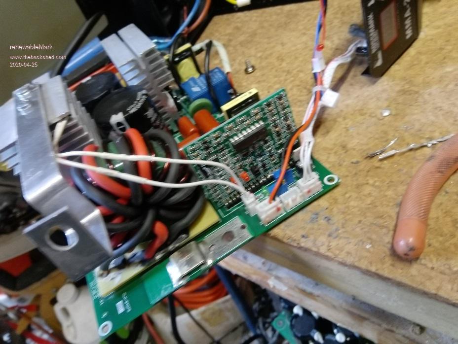
Cheers Caveman Mark Off grid eastern Melb |
| |
|
Wonder if I can still weld with it?
Cheers Caveman Mark
Off grid eastern Melb |
| |
Amazing, I didnt think it would work Well done Mark !! Maybe smallest rod size might work welding - but I suggest you leave it as a charger now. �Wonder what one turn would have done.... Edited 2020-04-25 15:40 by wiseguy
If at first you dont succeed, I suggest you avoid sky diving.... Cheers Mike |
| |
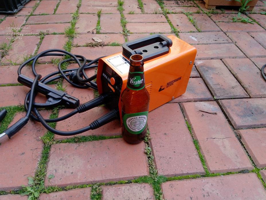 For those who haven't seen one, these are tiny and weigh stuff all. You would never know it has been modded by looking at it. If it goes bang at some point the transformer can be un soldered by the 6 pins and swapped into a new one. It was actually quite easy to de solder, just place a flat blade screwdriver under the sub pcb and heat the pins and it flexes a bit and lifts away when the solder is warm enough.
Cheers Caveman Mark Off grid eastern Melb |
| |
|
Thanks Noneya for the idea mate.
Cheers Caveman Mark
Off grid eastern Melb |
| |
Posted: 10:18pm
25 Apr 2020
Copy link to clipboard |
noneyabussiness
Guru
|
|
|
No worries, glad to be of help.. it was actually OZ's idea originally by memory ( well at least where i got it from ).. they are tough, mines be going as a charger for about 2 years now...
I think it works !! |
| |
|
Hey, what's the O/C volt of your modded one?
Cheers Caveman Mark
Off grid eastern Melb |
| |
Posted: 09:04am
26 Apr 2020
Copy link to clipboard |
noneyabussiness
Guru
|
|
|
96v.. but as was mentioned earlier, there is no " power " at that voltage.. its because its current controlled not voltage controlled..
I think it works !! |
| |
Posted: 09:05am
26 Apr 2020
Copy link to clipboard |
noneyabussiness
Guru
|
|
|
To be on safe side, i always hook to battery first... then power it up...
I think it works !! |
| |
| Page 2 of 2 |
