Re-Wiring the stator
First up, the old 42 pole conversion. The
42 pole stators are still the most common and easiest to source.
Click on the image to see the full size diagram. |
At right is
a diagram of the stator factory winding. I've labeled
the phases X Y & Z. Remember you can click on these
diagrams to see full size. This a 1 times 14 coils, making it a 1X14C using our naming scheme. |
|
This is a stator "split into two", so we end up with 2 times 7 coils in series. Best suited to 48 volts or 24 volts in low winds.
Using our naming scheme, this would be a 2X7C |
 |
This is how
we rewire the stator as 7 groups of 2 poles star configuration, suitable for most 12 and 24 volt applications, depending on how fast your turbine runs and what wire size the stator is. See What F&P is it? to identify which stator you have.
This would be a 7X2C |
|
And this is
how we can wire the stator to use for either star or delta
configurations. Anyone who read the Silicon Chip articles
I wrote will be familiar with this layout. The star/delta
option gives you the ability to connect the stator as
a star or delta. Delta will produce more power at high
revs, but star will start making power at lower rev's
and is the preferred option.
This is a 7X2C Delta |
|
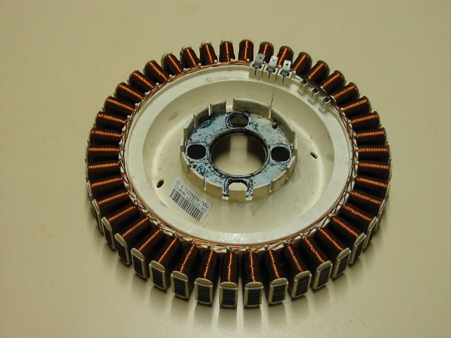
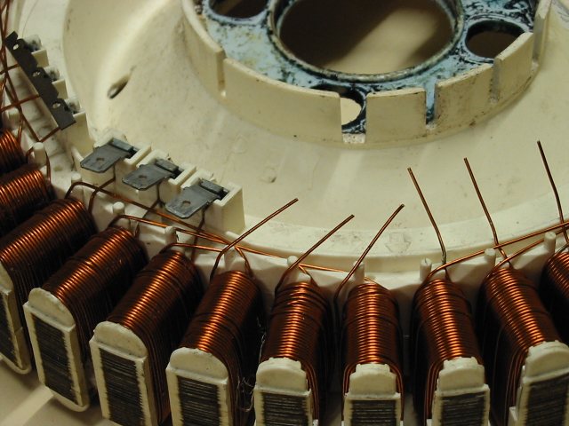
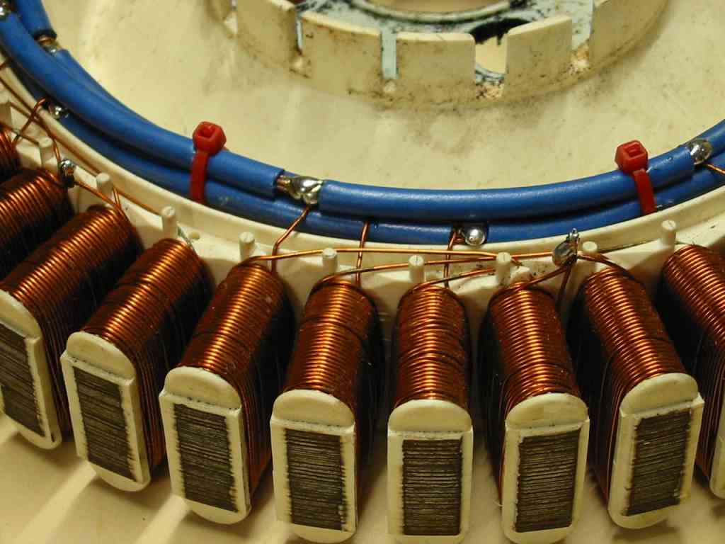
The standard
stator. First remove traces of corrosion and file off
any rust on the laminations |
|
Cut the winding
at every 6 poles. This will give you a total of 7 groups
of windings, each with 6 poles, 2 poles per phase. Remember
you can click on these photos for a closer look. |
|
With sandpaper,
clean the enamel off all leads for aprox 15mm from ends. |
|
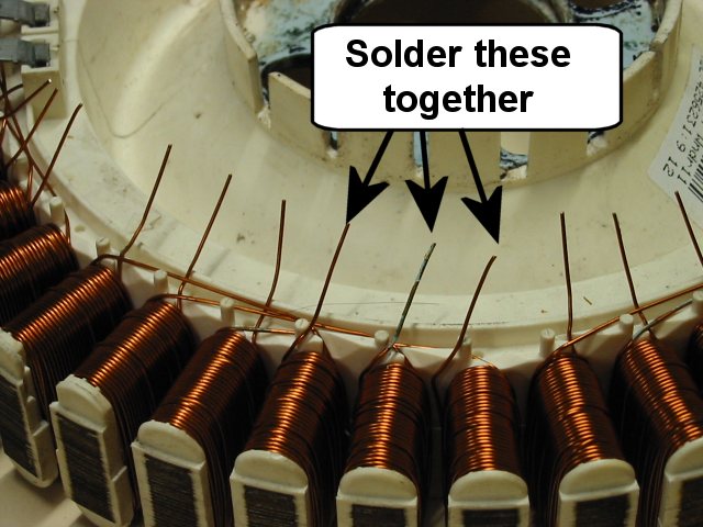
If you are making
a 3 wire star stator, twist and solder the star mid point
connections. |
|
| Strip lengths
of wire as shown. Use wire capable of at least 15amps. |
 |
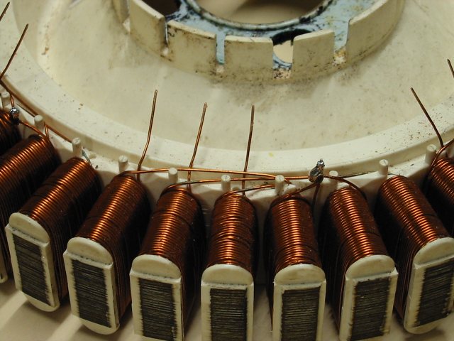
Solder three
( or six if you are going for the 6 wire star/delta option
) lengths of heavy electrical cable ( 4-5mm dia copper
) to the original connection terminal terminals, then
strip back 5mm at each connection point. Cut the cables
at the last connection point. This will form our power
"bus". Wrap each star end wire around the bus
wires as shown, and solder. You will need a good soldering
iron for this. |
|
Once all star
windings have been soldered, cable tie the bus wires to
secure the assembly. |
|
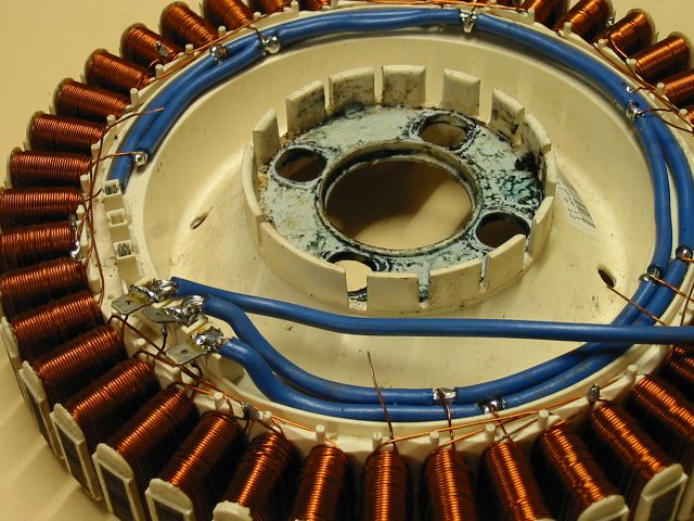
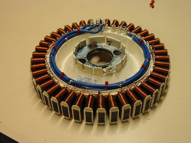
The finished
stator. Give the stator a good coating of varnish ( or
similar ) to protect from the weather. |
|
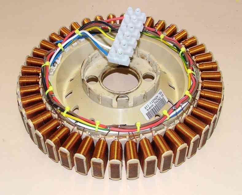
If you decide
to wire as a 6 wire delta/star configuration, you stator
should look something like this. |
|
| If you use a
6 wire star/delta configuration, the diagram at right
will show you how to connect the output leads together. |
 |
Next we'll look at the new 36
pole stator. I haven't done any testing with this model to
date, but reports from others indicate slightly less power
than the old 42 pole stators. However, the new 36 pole stators
don't have any of the cogging problems that have plagued the
42 pole stators for years. The 32 pole also give us a larger
range of re-wire options ( 36 divides down better than 42!)
The suggested rewire diagrams
are a guide only, there are no "use this re-wire with
this turbine to get this voltage" rules at this stage.
|
This is the
standard factory wiring. This would work best for a slow
running windmill, like a savonius type.
36Pole 1X12C |
|
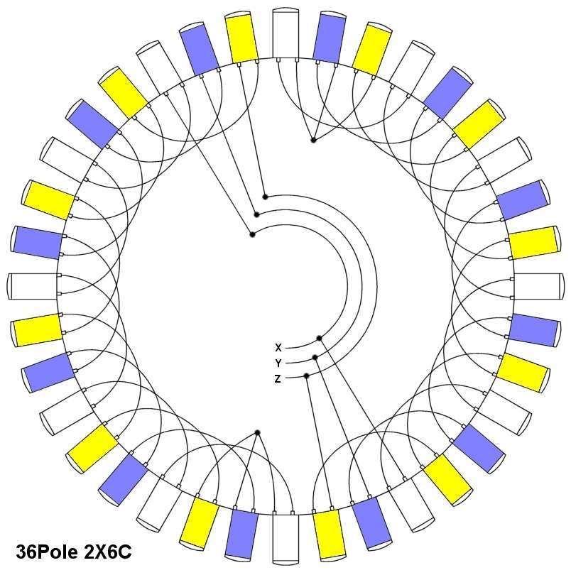
Rewired as 6
coils in series. Again suitable for low speed turbine
or high battery voltage ( 48 volts or above ).
36Pole 2X6C |
|
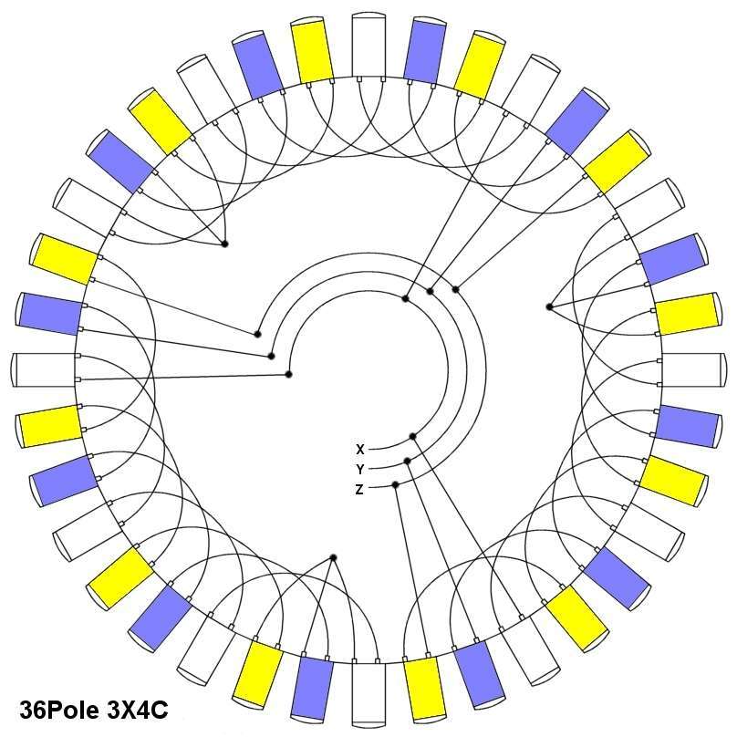
Rewired as 4
coils in series. Suitable for low speed turbine on 12
volt system or high speed turbine on 48 volt system. General
all rounder.
36Pole 3X4C |
|
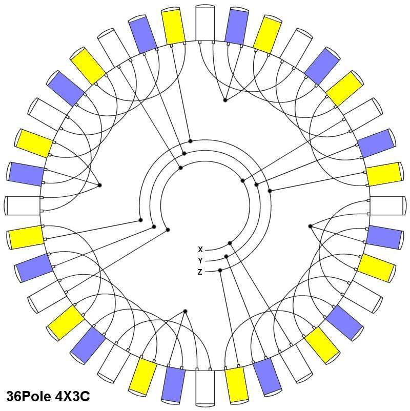
Rewired as 3
coils in series. 12 or 24 volt systems. Another general
all rounder.
36Pole 4X3C |
|
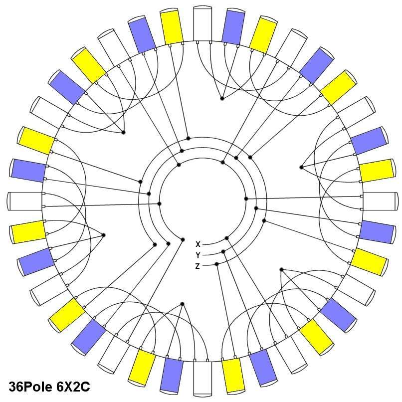
2 coils in series.
12 volts, high speed turbine.
36Pole 6X2C |
|
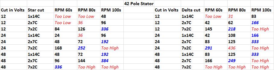
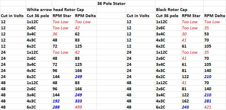
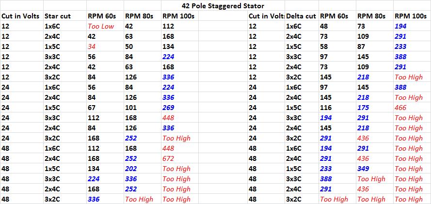
Forum member David has done some extensive testing of the F&P and put together the following Cut in Volts vs RPM tables. Using these tables, you can make a good educated guess on what would be the best rewire option for your available F&P hardware and system voltage.
The first table is for the 3 different 42 pole stators (60s, 80s & 100s)
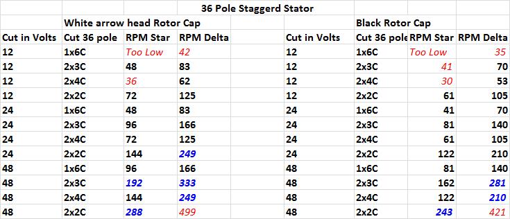
The Second table is for the 36 pole stator with White arrow head rotor cap and the newer stronger Black rotor cap.
Third and Forth tables are for Staggered stators (both 42 & 36) and are grouped in pairs. Example on 42 pole stator cuts “1x6C is used with 4x2C”, 1x5C used with 3x3C etc. On a 36 pole stator cuts “1x6C is used with 3x2C” then 2x4C used with 2x2C.
*Please note where it states "Too Low" refers to RPM below 30 and "Too High" is above 500 RPM. Too low RPM is most likely to stall the wind turbine blades at start up. Too High the turbine will likely be freewheeling and produce little or no power even in high winds.
Numbers in “Blue” need to be used with caution and will very much depend on blade setup and likely be used as a second “Higher RPM cut in” stator for say a dual operation. Also they can be halved or divided by 4 for use with “Cap Multipliers” described by Gordon. http://www.thebackshed.com/windmill/articles/GordonsCapMod.asp
Numbers in “Red” maybe be too low for most blade setups to allow a smooth start up without stalling them.
Hope this provides a rough guide to those new to here.
Thanks David.
There are also a couple of other
rewire options you may like to consider.
The 7 phase conversion. This uses a 42 pole stator with the magnet hub from a 36 pole
stator, a real mismatch in components. By itself, it doesn't
work, no output, but if you rewire the stator as a 7 phase
alternator, you get very good power output and no startup
cogging problems.
Details
here.
Staggered windings involves re-wiring the stator into groups with different coil counts. Different coil counts mean different cut in RPM's, and this gives a alternator with a better power curve.
Details here
|