Menu
Home Page
Getting Started
Info & Projects
Articles, Readers Windmills
Windmill Kits & Parts
Photo Gallery
Forum
Links
About Us
Search


Piclog - PicAxe Logger Controller

   I needed a logger. Some way to record windmill data during the day while I was at work. And as I'm a big fan of the PicAxe chips, a 08M chip had to be the brains. This logger controller, along with the PC software, records battery volts, current drain, windmill watts and windmill RPM. The controller can also operate on its own as a simple shunt regulator. The PicAxe based controller is a simple circuit, and sends raw data to a PC via the serial port. All the calculations and calibration is performed by the PC software.

I call it PicLog. Please note, if you want to build this project, you will need some experience with electronics, including making your own circuit boards, and programming in Visual Basic and PicAxe basic.

As this is an ongoing project, I will occasionally release updated versions. Each new version will supersede the old version, and the old version's software will no longer be available to download.

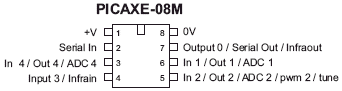
There are two halves to this project, the PicAxe circuit board, and the PC software. The PicAxe is used to make simple measurements, and send the data to a PC via a 3 wire serial cable. The software on the PC converts this raw data into real values we can understand and record. I've called each burst of information a "Heart Beat"

There are two different configurations. The PicAxe used, a o8M, has only 4 usable pins, so this limits our options. I could have used a 18X chip to give us several more pins, but I wanted to keep this project simple, and I had a few 08M chips in stock. But the software could easily be used on a 18X chip.

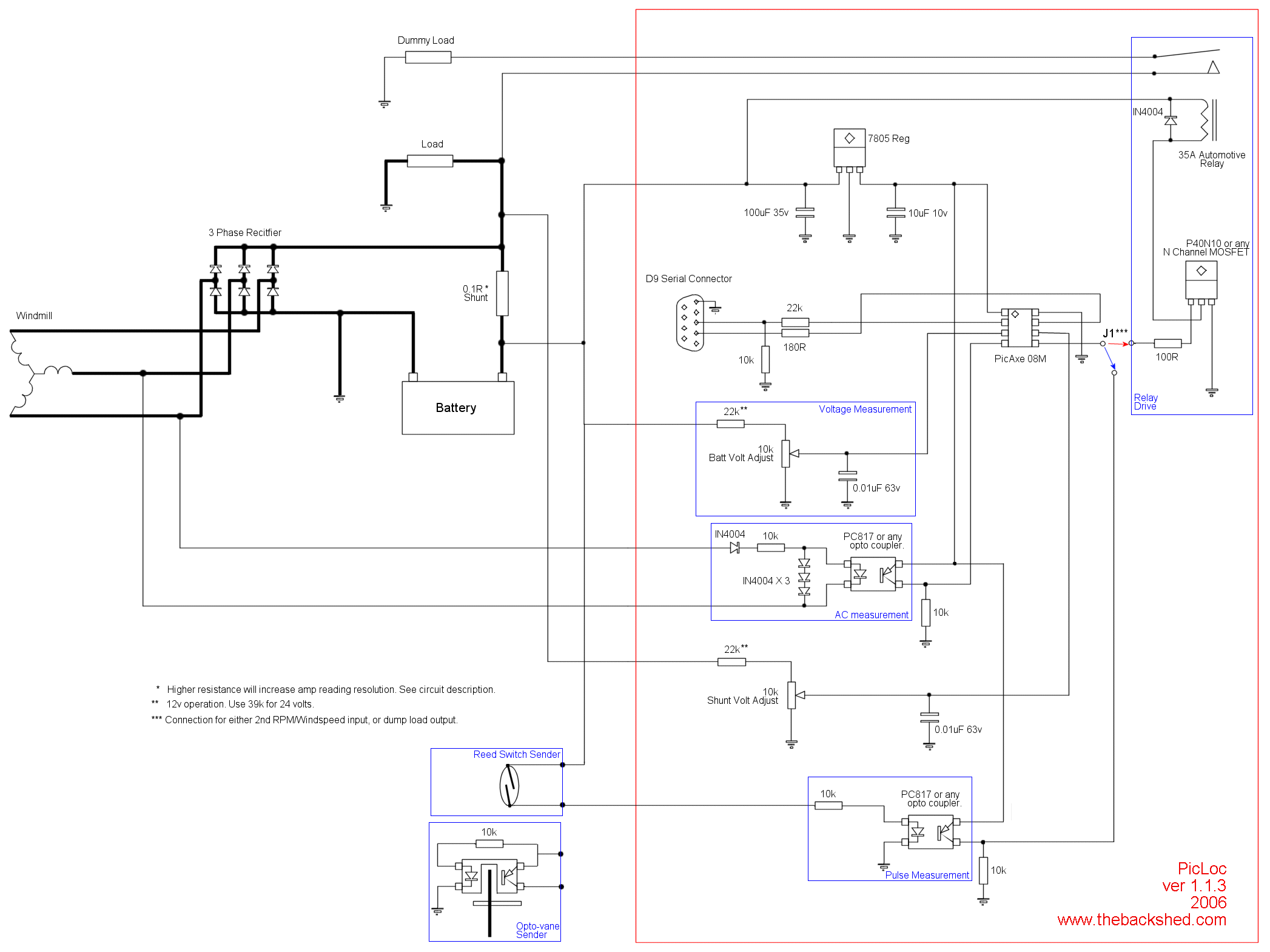
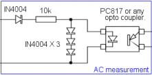
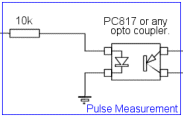
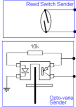
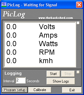
1. Logger - Regulator. Measures Volts, Amps and Windmill RPM or Wind Speed. The last PicAxe pin is used to switch the dump load.

2. Logger Only. Measures Volts, Amps, Windmill RPM and Wind Speed.

PicLog. Ver 1.1


Click to enlarge

I'm using two of the ADC inputs of the 08M chips to measure battery voltage (pin 3) and shunt voltage (pin 6). The PC software calculates battery current by comparing the difference in battery and shunt voltage, ie if the battery is 12 volts, and the shunt measures 12.2 volts with respect to the battery -ve, and the shunt is 0.1 ohms, we can work out amps using 12.2v - 12v = 0.2v, so 0.2v / 0.1ohm = 2amps. The PC software actually uses a different method to work out amps, but you can get the idea. The 2 ADC inputs are protected by 4.7v zeners, and 0.01uF caps filter out any spikes.

Windmill RPM is measured by sniffing the AC directly from the windmill, before it passes through the bridge rectifier. The PicAxe can count pulses per second, so we use this to work out RPM. There is a opto coupler there to isolate the AC from the battery side of the bridge rectifier, and provide some protection for the 08M input (pin 4).

You could also use an opto-vane sensor or reed switch to measure windmill rpm. Your windmill may have a DC output, so you cant use the AC circuit above. If this is the case, you can replace the AC measurement circuit above with this one.

This will take a pulsed signal (9 to 30 volts ) from a speed sender and feeds the PicAxe input. Again there is an opto coupler there to protect the PicAxe from spikes on long wire runs. Below are the circuits for reed switches or opto - vane senders. You can find opto - vane senders in old printers or photo copiers, even some old floppy disk drives. If you use a reed switch, I suggest you add a 22nF capacitor across the contacts to filter out spikes

We can also use this input circuit for wind speed measurement, using a home made anemometer, the one shown uses 1 magnet and a reed switch. The PicAxe measures RPM or Wind Speed by counting the number of pulses in a 1 or 2 second interval, and this can be a problem if you want to measure low wind speed. The anemometer shown has one magnet, so the reed switch only pulses once per revolution. At low wind speed, it may only spin 1 or 2 times per second, so this will give inconsistent wind speed measurement. It really needs 4 or more magnets to operate reliably at low wind speed, but once the wind has picked up the reading will be more accurate even with only one magnet. Another "fix" is to increase the duration the PicAxe uses to count pulses. To make my anemometer work correctly, I added a extra magnet, and increased the count period to 2 seconds.

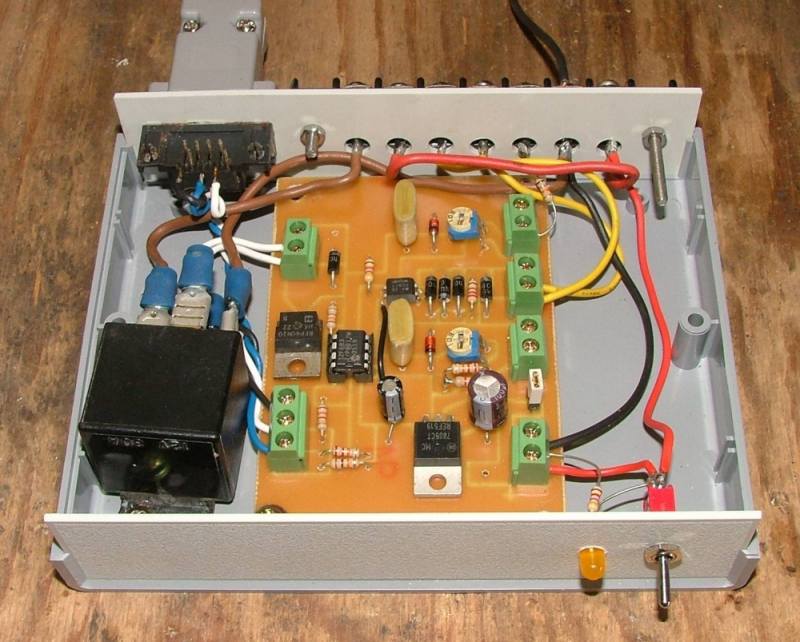
Dump Load. If the battery voltage is too high, a mosfet ( from pin 5 ) drives a automotive relay to switch a dummy load ( couple of 12v spotlights would do ) across the battery to drain off the excess power.

The circuit can run on either 12v or 24v, but there are a couple of resistors that need to be changed. If you wanted to quickly change from 12 or 24 volt, a double pole switch could be used to change the resistor values. To keep it simple, I'll use 12v for the rest of the controller description.

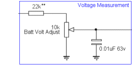
I machined my circuit board on my cnc router, but its a fairly simple circuit and you could use veroboard. If you have a cnc router drop me a email and I'll send back the dxf file.

PicAxe software.

Pretty simple this one. The 08M measures the battery voltage, shunt voltage, RPM and or Wind Speed, then sends this info out the serial connection at 4800 baud. The two inputs are measured as 10bit, or 0 to 1023, where 500 is equal to 12 / 24 volts. This is converted to a real value in the PC software. If the battery voltage rises above 14v ( =580 in the PicAxe , 1 volt = 40 ), it switches on the mosfet. If the voltage drops below 13 ( =520 ), it switches off the mosfet. These switching points can be changed to suit your own preferences, but this means you need to reprogram the picaxe, easy enough to do.

Version 1. Logger Regulator

Start:
SYMBOL RPM = W2
SYMBOL Amp = W1
SYMBOL Volt = W0
SYMBOL Mode = b8
Mode=0

Main:
readadc10 4,Volt  
readadc10 1, Amp  
Count 3,1000,RPM  
sertxd("[<V>", #volt, "</V><I>", #Amp, "</I><R>", #RPM, "</R><M>",
#Mode, "</M>]")
if Volt>580 then SwitchToLoad 
if Volt<540 then SwitchToCharging
goto main

' ########## Switch on dummy load

SwitchToLoad:
High 2
Mode=1
goto Main

' ########## Switch off dummy load  

SwitchToCharging:
low 2
Mode=0
goto Main

Version 2. Logger Only.
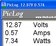
Start:
SYMBOL WSpeed = W3
SYMBOL RPM = W2
SYMBOL Amp = W1
SYMBOL Volt = W0

Main:
readadc10 4,Volt  
readadc10 1, Amp  
Count 3,1000,RPM
Count 2, 1000, WSpeed
sertxd("[<V>", #volt, "</V><I>", #Amp, "</I><R>", #RPM, "</R><S>",
#WSpeed, "</S>]")
goto main


PC Software.

Written in vb6, the windows application does all the number crunching and logging. There are 4 screens, Main display, Setup, Calibration, and Logs.

The main display shows the current Battery voltage, Current, Watts, RPM and/or Wind Speed. This is updated on every heart beat from the PicAxe, every 2 to 3 seconds. Typically the data from the PicAxe would look like...

[<V>520</V><I>540</I><R>12</R><S>23</S><M>0<M>]

V is Battery Volts, A is Shunt Volts, R is pulses per second, S is Wind Speed pulses per second, M is mode ( dummy load on or off )

The program breaks this info up into its individual values, then uses its calibration settings to get our true battery voltage, Battery current, Watts, RPM, WindSpeed and Mode. This info is displayed on the screen.

If you click the Start button in the logging section, the program will start recording the values into a text file. A new text file is started for every day. The interval is set to 60 seconds be default, but this can be changed from 10 seconds to 600 seconds ( 10 minutes ).

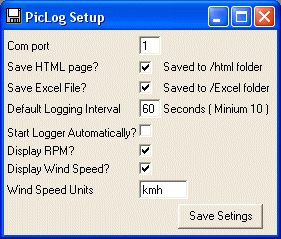
The Program Setup screen is used to set some general program settings, and saves the information to a text file called prog.cfg.

  • Com Port: Set to the com port on your PC that the PicAxe serial cable is plugged into.
  • Save HTML Page: Updates a web page every few seconds with the loggger data, more on this later.
  • Save Excel File: Creates an Excel file, one for every day, with the log history.
  • Default Logging Interval: Pretty obvious.
  • Start Logger Automatically: Logging starts on program start.
  • Display RPM: Turn on RPM display.
  • Display Wind Speed: Turn on Wind Speed display.
  • Wind Speed Units: What measurement base for wind speed ( ms, knots, etc )

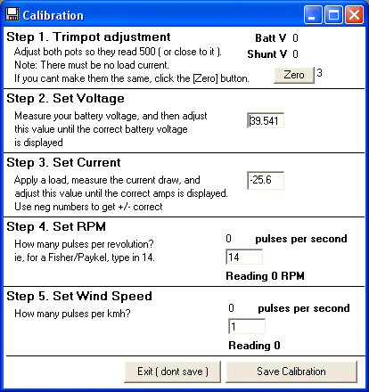
The Calibration screen is used to set up the software. Just follow the steps. Its saves the configuration as a text file called settings.cfg. Dont be tempted to edit this file, if there is a problem with it the program will crash.

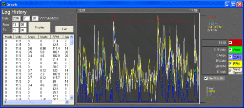
The Show Logs screen displays logs, and includes graphs. Just enter in a date and hit Display. You can then narrow down the time spread using the From and To time values. The graphs are scaled to the max and min values. If you move your mouse over the graphs, it will display the value and time, depending on where your mouse pointer is. You can also turn off and on individual traces.

HTML Page. You need to have a web server installed on the PC and a basic understanding of IIS administration if you want to use this function. If the Save HTML pages it turned on, on every heart beat the program will open a file in the HTML directory called "template.asp". It searches for tags in the HTML code, and replaces these with the actual data.

<VV> = Volts, <AA> = Current, <WW> = Watts, <RR> = RPM, <SS> = Wind Speed, <TT> = current time.

The web page is then saved as Logs.asp. You can map the HTML directory as a virtual directory in your web server. If you would prefer the page saved in another format ( html, php, jsp) please let me know.

This is a sample page, I was displaying live data here, but there were too many visitors and my poor old satelite connection was crying for help.

Batt Volts 12.45 volts
Current 1.05 amps
Watts 13.0 watts
RPM 92 rpm
Wind Speed 21 kmh
Date Stamp 8 Oct 2006 13:30

PicLog. Ver 1.2

This new version uses a much more accurate method of current measurement. The previous version used the PicAxe as a difference amp, and not a very good one at that. Current resolution was limited to about 50 steps, so if you wanted to read in 0.1 amp steps, you could only read from -2.5 to +2.5 amps.

By moving the shunt resistor to the -ve side of the battery, we increase our resolution t0 over 150 steps, depending on what shunt resistance you use. The PicAxe ADC is sensitive to 0.004 volts, so if you want to measure in 0.1 amp steps, you would need a 0.04 ohm shunt. Using ohms law....

R = V * I
R = 0.004 * 0 .1
R = 0.04 ohms

If you have a 0.1 ohm shunt....

I = V / R
I = 0.004 / 0.1
I = 0.04 amps resolution

The disadvantage of using a shunt resistor on the battery -ve is we can no longer easily read -ve amps ( or load ). Since the PicLog was designed to record windmill performance, and not battery load, so we dont need to record -ve amps. But if you do want to record -ve current, there is another solution, keep reading.

Originally the PicLog circuits -ve or ground connection was connected to the battery -ve. We now need to put the shunt resistor between the source -ve ( our windmill generator ) and the battery -ve terminal. Our PicLog circuit now uses the sources -ve as its ground terminal. This means the PicLog's -ve/ground is slightly below battery -ve/gound terminal. In industrial electronics this is a bit of a no-no, we loose "true ground" at the PicLog, but for a simple windmill logger its perfectly acceptable. We also change the current sense input lead on the picaxe to the battery -ve terminal, and remove one resistor on the circuit board. Below ( and included in the download ) is the updated circuit diagram.

There is a slight change to the PC software. Version 1.1 worked out amps by looking at the difference in the two ADC values from the PicAxe.

V1 = Battery Voltage
V2 = Shunt Voltage
VoltOffset = zero point
AmpDivider = Constant used to convert the PicAxe ADC output to true amps, part of the calibration process.

BattAmps = Round((V1 - V2 + VoltOffset) / AmpDivider, 2)

The new version, 1.2, now just reads the V2 directly as a amp value, it no longer needs to compare it to the battery voltage.

BattAmps = Round((V2 - VoltOffset) / AmpDivider, 2)

The calibration screen has been changed. I left the VoltOffset variable there so we could still use the software to record + and - amps. There are some hall sensor current sensors available that give us a voltage depending on amps. 0 amps = 2.5 volts, so a change in current up or down ( + or - ) gives us a voltage from the hall sensor that goes up or down from 2.5 volts. So the PC software will work with either a shunt resistor or a hall sensor. If you want to use a hall sensor, just omit the shunt resistor and connect the PicLog -ve to the battery -ve

A couple of good hall sensors worth looking into are...

http://www.allegromicro.com/sf/0750/ this is the ideal sensor to use.

http://www.dse.com.au/cgi-bin/dse.storefront/450357770e5bf3a42740c0a87f9c06f6/Product/View/Z2620 Not very linear, but cheap and easy to get in Australia at most Dick Smith stores.

I've also added a Watt Hours reading to the main screen. This is set to zero on program start or at midnight, so it shows the total watt hours for the day.

If you built the Ver 1.1 PicLog circuit board its a simple task to modify the circuit to suit the latest version, you only need to remove the pots and add a couple of jumpers and 1k resistor. For the latest version I designed a circuit board in Express PCB. Express PCB is a free PCB design program available from http://www.expresspcb.com/


You can download everything by clicking here. The zip file contains the circuit diagram in GIF and PDF format, the PicAxe code, the PicLog application and source code, and mscomm32.ocx and scrrun.dll( see below ), the HTML directory and template file, and a few sample log files.

Notes.

  1. If there are bugs in the software, or if you have a suggestion, please let me know . But dont ask for help with modifying the source code or explaining how it works, it comes as is.
  2. If you get the error "Component mscomm32.ocx or one of its dependencies not correctly registered..." then you need to copy the mscomm32.ocx file ( comes in the Zip file ) into your c:/windows/system directory. You may also need to copy the scrrun.dll file as well. These are Microsoft run time file that may not be on your computer.
  3. The program isn't perfect, and may/will crash from time to time. I'll improve it as time allows.
  4. Feel free to reuse the PicLog software and design for your own projects, but credit where credit due, dont forget to mention where you got it from.
  5. I changed the serial data stream to use <I> instead of <A> for the current measurement about half way through developement, big mistake as there are now two different versions of the PicAxe and PC code. Download the latest version to fix this problem.