 |
|
|
Site Navigation
Projects & Information
»General Information»Wind turbine Projects »The F&P Smartdrive »Electronic projects »Microcontroller projects »Miscellaneous Kits & Parts
»Basicly Natural Pty Ltd»PVC & Aluminium blades »Scale model farm windmills »Price Watch Discussion Forums
Handy Links
»Wind»Solar »Electric Vehicles »Electronics »Micro Controllers »General Interrest About TheBackShed Getting Started Privacy Policy |
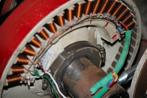
In Johns words.... Mounting the F&P motor Working on my pedal generator I had to make a hub to hold the two bearings and support the stator accurately centred inside the rotor. I dont have a lathe or much in the way of machine tools so I had to put the gray matter to work! This is what I did, I found a length of two inch internal diameter water pipe and cut off a piece shorter than the F&P shaft being careful to get the ends as square as possible. Quite a long time with a drill and emery flap wheel opened the ends enough for me to be able to press the bearing in. In hindsight I could have just slotted the ends with a hacksaw, pressed the bearings in then welded up the hacksaw cuts, not truely accurate but good enough for the two knackered bearing I have to put in. So I had two bearings and a piece of pipe they would fit in. There was a ridge on my shaft so I ground that off as neatly as I could. I put the rotor on the shaft and placed the rotor on a level surface with the shaft vertical above it. I used the original plastic nut to mount the rotor as I have been told it is very difficult to get the rotor off the shaft without this very hand nut. I used tape to close the four mounting holes in the stator putting the tape on the outside and also put tape around the ring of plastic tabs that are on the other side of the stator. Then I dropped the stator over the shaft and into the rotor. I cut strips of plastic from a plastic carton and put these all around between the coils and the magnets. It was quite a struggle to get the last few in but when I was finished the stator was being held centrallised inside the rotor. One bearing I slid over the shaft and used just a little mastic to seal the edge of bearing to the centre of the stator. Next I dropped my piece of water pipe over the shaft and around the bearing. The second bearing got put on from the top and tapped down into the end of the water pipe. I mixed up enough polyester resin to fill the space between the water pipe and the ring of plastic tabs. Most of the resin stayed in and there was only a little leak in one of the stator mounting holes. I should have fluffed up some glass fibres and put them in the resin but none was on hand, next time I will be prepared. When the resin set (overnight) I pulled the bits of plastic from around the magnets and was very pleased to see that the rotor turned without catching anywhere. The nut made it easy to draw off the rotor and pick out the little dribble of errant resin, I removed the bits of tape at the same time then put the rotor back on but not screwed quite as far to ensure clearance with the stator. There was only one last bit to do and that was to fit a large hose clip of the screw tighten type around the ring of plastic tabs as there is very little binding to the solid resin piece. I can take the rotor off by unscrewing its plastic nut and then by releasing the hose clip the stator comes away easily too. This seems to be plenty strong enough for the job and the water pipe is plenty heavy enough to weld your support to plus I think it gives adequately rugged support for your propeller hub. I hope this idea is useful to someone!
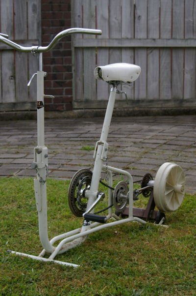
Some of the things I recall from when I added a F&P to an old exercycle:
I remember the book by the aforementioned Lance Armstrong mentioned 500 watts in training but that was his effort as measured by the machine. If you suppose the bike and generator is 50% efficient then you are putting in 100 watts. Easy enough then to realise the F&P is really too big and it is a heck of an effort just to overcome the cogging drag so I took my trusty jig saw and cut about 60% of my stator away!
Notice the two stage gearing, I have since gone to a single stage configuration which means the F&P now spins at about 250 rpm when pedalling at an easy 85 rpm. Available output at not-too-exhausting pedalling rate is about 90 watts. Thanks John
|
||