
|
|
Forum Index : Microcontroller and PC projects : Programmable calculator on Pico DIY
| Author | Message | ||||
| zeitfest Guru Joined: 31/07/2019 Location: AustraliaPosts: 381 |
Well I have made progress on my programmable calculator project. It runs on the Silicon Chip Pico backpack kit. Programs can be run from SD card or a connected PC using a serial terminal. The SD card can be read and written from within programs. At startup a simple screen is displayed with numeric and program buttons. 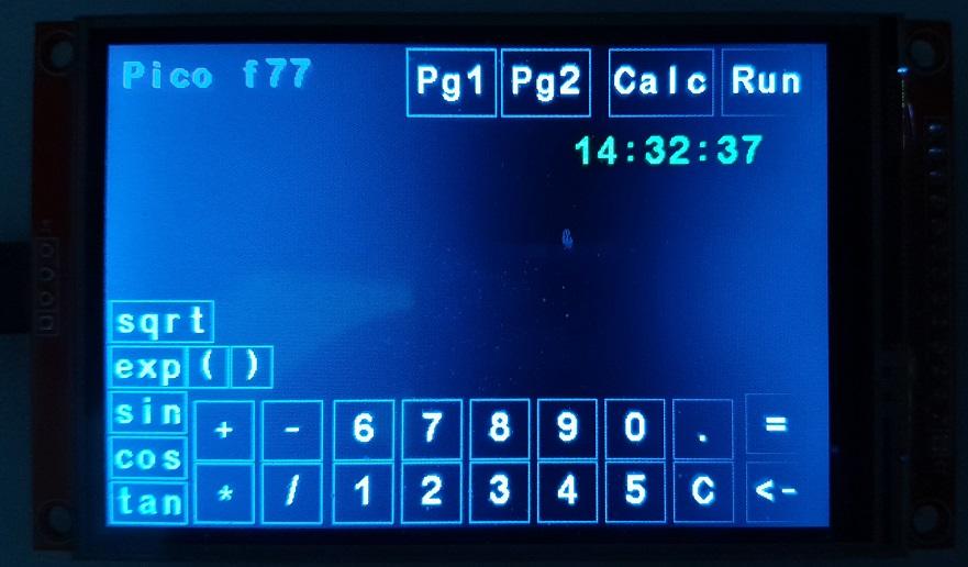 The three program buttons load associated programs on the SD card, I have imaginatively titled them "Program1" ,..2, Calc. The Calc program is very small and just reads and evaluates a math line input by the operator. 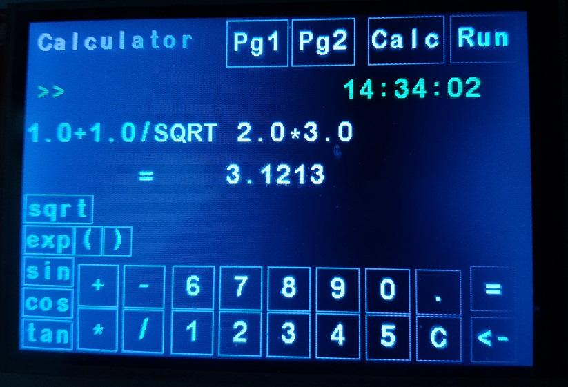 The next program is a trivial example that reads a temperature value, does a little math and presents the result (Celsius). The input is stored/used using a simple variable as usual in programming. (ed) That is basically the intended main use - a program runs using small amount of user numeric input, and presents the result. More significant math would be run by a stored program, so the key pad is mainly intended for some numeric input. A lot more functions are available via the program. 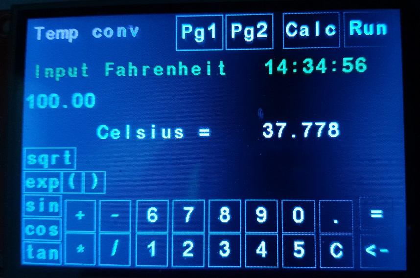 The arduino environment means things can be added easily, eg per I2C, so I added a 3231 RTC and the time is available as variables in the program. The next photo shows a program that uses the RTC value to calculate the suns position. It is in a loop so it updates once a second. It also reads the SD card for parameters. I hope to add things like a DA converter and so on. The interpreter already has AD and port bit commands so it should be straightforward. 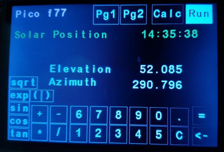 Now for the de-bugging....  .(arrrgh!) .(arrrgh!)The Pico has some issues and the backpack has limits as well so I am looking at other platforms as well. They are pretty similar though I guess. Edited 2024-02-09 16:24 by zeitfest |
||||
| Frank N. Furter Guru Joined: 28/05/2012 Location: GermanyPosts: 813 |
Very cool!  I'm planning something similar! Frank |
||||
| zeitfest Guru Joined: 31/07/2019 Location: AustraliaPosts: 381 |
Programs are developed using a PC/serial connection, a program is just a text file and loaded and run from the PC. It is listed as the program runs. To run "headless", the SDcard has three files which are called and run by the screen buttons. The calculator and temperature example programs are lightweight enough. REAX is a temporary name of READ, it accepts user input from the display and stores it in a variable. The calculator pgm reads a user line into a character array variable which is then evaluated by EVAL, which evaluates it and also writes the result to a result field. The temperature pgm reads the user value into a floating point variable which is then used for the arithmetic. The result is written to a result field. The solar position pgm is a lot bigger (goes on for pages) but yada.. The "descs" routine just puts some description texts on the screen. Quite a bit to do yet !! "Calc" ... Running PROGRAM calcul8 CHARACTER*20 eqn CALL descs ( ) REAX eqn EVAL eqn END SUBROUTINE descs ( ) QZFTXT QZFA "Calculator" QZFTXT QZFB ">>" QZFTXT QZFD " =" RETURN END "Pg1" ... Running PROGRAM tempconv DOUBLE fahr, celsius FORMAT (F9.3) CALL descs ( ) REAX fahr celsius = 5.0 * ( fahr - 32.0 ) / 9.0 WRITE (*,0) celsius END SUBROUTINE descs ( ) QZFTXT QZFA "Temp conv" QZFTXT QZFB "Input Fahrenheit" QZFTXT QZFD "Celsius =" RETURN END Edited 2024-02-11 10:19 by zeitfest |
||||
| rea23 Newbie Joined: 16/09/2022 Location: SwitzerlandPosts: 26 |
Very nice project. I would be very interested to know what formulas you used to calculate the position of the sun. Do you have a link or even better a link to your program? |
||||
| zeitfest Guru Joined: 31/07/2019 Location: AustraliaPosts: 381 |
This was the base of it (ed - ie the sun program example) - IIRC it spins on GMT, I added a trivial modification for the local Sydney time hour offset, ( valid after 10/11 am - it needs to handle the possible day/month/year change yet  ) . ) .sunae ed - Some time ago I checked the results using the NOAA site and it matches OK, at least for the locations used. Edited 2024-02-12 12:54 by zeitfest |
||||
| zeitfest Guru Joined: 31/07/2019 Location: AustraliaPosts: 381 |
PS if you are after astronomy, cdeagle has excellent programs, not sure of current activity though |
||||
| zeitfest Guru Joined: 31/07/2019 Location: AustraliaPosts: 381 |
Yessss !!! CLICKY BUTTONS !!! I got sick of trying to hit dinky little screen buttons so I added a keypad. It uses a (ed - was typo) TCA8418, cheap and ultra-easy via an Adafruit breakout module running off I2C. Definitely the way to go. Wiring the keypad itself is tedious but a pcb will solve that. The screen is much clearer and the lot will fit into a standard case. Much better ! As before, the Pn keys load/run programs from the sd card, otherwise programs can be sent from a PC. Making progress.. 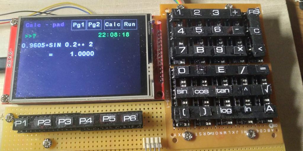 Edited 2024-03-24 22:53 by zeitfest |
||||
| zeitfest Guru Joined: 31/07/2019 Location: AustraliaPosts: 381 |
First assembly... The design was a bit of a gamble, there is a trade off between size, screen size, function, number of buttons, practicality, and so on. it has worked out (a lot) better than I thought likely. The case is off-the-shelf about 16 x 9.5 cm, I mashed the keys a bit fitting it and it looks a bit tired, I have to add trim etc and cut the case more accurately though. There is a usb socket on the left had side for power ( the pico ) and serial ops/programming, there is still space in the case for a rechargeable battery for power. Sorry for photo quality  , I hope it is of interest ! , I hope it is of interest !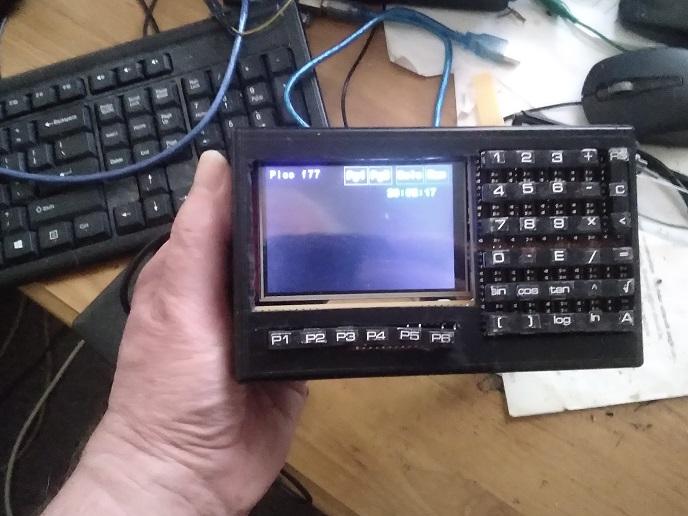 |
||||
| okwatts Regular Member Joined: 27/09/2022 Location: CanadaPosts: 51 |
Always of interest! Might be a little large to carry in your pocket but guaranteed to acceptable for Nerds! Had a look at the Adafruit breakout board looks to be a good option for an add-on. What kind of buttons are used and do you plan on doing a board layout for the keys? I am interested in your software also and would appreciate a chance to play with it if the code is available. Thanks for sharing. |
||||
| zeitfest Guru Joined: 31/07/2019 Location: AustraliaPosts: 381 |
Yes I considered a 5x5 keypad which would be smaller, make a good wifi remote size, drop the trig buttons for 5 program buttons instead. The keypad is a "sea of holes" proto board cut down to approx 6cm x8.5 cm. The keys are the standard 6mm button switches with labels glued on with epoxy, that is probably not durable but there are switches with label fittings for a final version. I will try to get some 6x5 switch keypad pcbs made, I am out of date with pcb software so it may need a learning curve  Not sure yet if I can distribute it freely, it has software fron eg Adafruit /earlephilhower/etc as a foundation so there may be issues. Also there is the thought, why distribute something if it is likely to be copied/steamrollered/sold for attempted commercial advantage, with little or no credit back? A project like this has quite some investment in it. |
||||
| zeitfest Guru Joined: 31/07/2019 Location: AustraliaPosts: 381 |
The wiring is pretty messy but OK, after a few dumb mistakes  . The Adafruit TCA8414 module is at the top left. . The Adafruit TCA8414 module is at the top left.A main aim for this was to have a calculator/device with a reasonable screen display. There are already commercial calculators of course, the expensive ones have good displays and often programmable (Python, Basic), but the cheap ones are tiny and crap to use !! The 3.5 inch is still not that big, but long equations will probably be used in programs instead I guess. Wondering if spaces should be enforced. Who uses calculators these days anyway !!?? 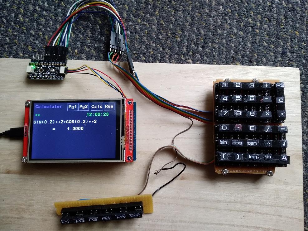 |
||||
| Frank N. Furter Guru Joined: 28/05/2012 Location: GermanyPosts: 813 |
I do!!! I am very interested in your project! I had built a USB keyboard for an emulator with an Arduino Pro Micro. You are completely free with the matrix! PET2001 KEYBOARD PROJECT Wouldn't that also be something for your calculator? Frank |
||||
| Mixtel90 Guru Joined: 05/10/2019 Location: United KingdomPosts: 5729 |
I wonder if MMBasic would do the keypad scanning if you use KEYPAD twice? Use a different set of row inputs and a different variable. you may get 4x8 keys then. 12 GPx pins needed. Mick Zilog Inside! nascom.info for Nascom & Gemini Preliminary MMBasic docs & my PCB designs |
||||
| zeitfest Guru Joined: 31/07/2019 Location: AustraliaPosts: 381 |
Now thats a keyboard ! I had not considered adding a full keyboard, your project has good capabilities there. At this stage the keypad is intended mainly for number input, programs are written on a PC instead. My experience is, to edit full text on the 3.5 screen requires a small font which can be a problem. The TCA8414 condenses the 6+6 keypad lines to two I2C lines and it scans, does debouncing etc so it is OK so far. It will scan up to 8x10 lines, but not USB, that might be necessary soon. |
||||
| okwatts Regular Member Joined: 27/09/2022 Location: CanadaPosts: 51 |
I think this is an admirable challenge but adding an external keyboard will make this quite large. If this is for your own use and enjoyment then that is great. The challenge is keeping the cost reasonable to get something you can't get by other commercial means. I have a few HP calculators HP48G, 35S, and their keyboards are quite nice but the display is limited. Using button keys are quite effective for a project like the following https://obsolescence.wixsite.com/obsolescence/kim-uno-summary-c1uuh https://obsolescenceguaranteed.blogspot.com/2022/12/the-2-apple-1.html where you are emulating a Computer with a limited display. I also use a HP48 app on my smart phone(all on screen keys and display). The disadvantage is the high cost of the phone to get the good display(and portability). One app that I remember using was on a Palm Pilot that was interactive and could draw curves on the screen, but you could enter your own formulas in algebraic notation. I have used the 3.97 inch IPS display on the STMF4 board that Disco4now is supporting. It has the 800x480 display so might be a better display to combine the keyboard with display that could keep the size down. It appears from what you indicated your program environment for the F77 is using the Arduino platform so it might be possible to port that to the STM rather than the RP2040. At any rate I am enjoying following the progress and I will be interested to see how it develops. Edited 2024-03-29 04:06 by okwatts |
||||
| Frank N. Furter Guru Joined: 28/05/2012 Location: GermanyPosts: 813 |
Exactly! And with the Soarer firmware, you can build a miniature USB keyboard that works on any computer such as a PC or Raspberry Pi. You can realize them directly on the board with these discs: 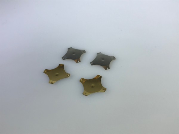 Or with these SMD buttons here:  Then you can connect the keyboard directly to the PicoMiteUSB via USB. Frank Edited 2024-03-29 20:31 by Frank N. Furter |
||||
| zeitfest Guru Joined: 31/07/2019 Location: AustraliaPosts: 381 |
For a calculator/portable instrument display type device, only a I2C keypad is needed at this stage so I will stay with that, maybe add USB i/o in future. One aim is to keep the size down, the 3.5 fits -just- with keypad into a jiffy box and it is hand held size. There is also a smaller screen 3.2 inch 240x320 which might have better drivers but has less resolution. I wanted to have the display readable at say a meter distance, meaning a moderate size font, but the display software is a bit limiting. I will check the STMF4 board, any more details ? |
||||
| Mixtel90 Guru Joined: 05/10/2019 Location: United KingdomPosts: 5729 |
I agree that that's a possibility, but if you were to use a PCB with the Pico, keyboard and display on it you could make it smaller and more rugged - and get rid of a third party keyboard scanner. Another possibility, which you may have tried, is to ditch the mechanical keyboard and run the display in portrait mode with an on-screen keypad with drop-down menus for lesser-used functions and settings. You may want to look for a wider display in this instance. It might be possible to keep the keypad on-screen in portrait mode. Just a thought. :) Mick Zilog Inside! nascom.info for Nascom & Gemini Preliminary MMBasic docs & my PCB designs |
||||
| zeitfest Guru Joined: 31/07/2019 Location: AustraliaPosts: 381 |
There are a number of ways of course, I did have the buttons on-screen but they are too small ! And then I wanted to avoid going "all-glass" as it would then be basically the same as a mobile running an app. And the click is good. In any case I have replaced the rats nest keypad(left) with a pcb prototype (perched on the box, right), which carries the tactile switches, TCA8418 module and its I2C socket, much cleaner. For a few $, it is well worth it and will be way more robust. 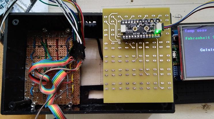 The module just stores the keypress(es) and waits for a I2C data request. (edit - it also provides debounce and ESD protection) I think it is worth supporting Adafruit stuff, the bits can be bought easily from Jaycar/Altronics/CoreElectronics/LittleBird, all give good service and make it pretty easy. CoreElectronics and LittleBird are web-order, it is worth putting up with the online catalogs, CoreElectronics more likely to have stock, LittleBird has a more eclectic range. Yu can always order direct from Adafruit but then pay postage, exchange rate, yada.. Sure a keypad scanner can almost certainly be done with a Mite. But a downside of projects that try to do everything in "Mite / MMBasic" is that they tend to exclude the supply chains who have existing products. Edited 2024-04-10 16:01 by zeitfest |
||||
