
|
|
Forum Index : Microcontroller and PC projects : Single AA battery tester - constant current?
| Author | Message | ||||
| PEnthymeme Newbie Joined: 27/12/2023 Location: United KingdomPosts: 35 |
Happy Sunday (UK time) For a local "maker club" (with adults / children) I want to build a "simple" battery tester to test the capacity of single AA batteries. The idea is to test various brands, including rechargeable, capture voltage over time and use the data for discussion. Current can then for each sample be calculated I=V/R -- this allows the mAh capacity of the battery to be calculated. But as the voltage and hence the current is changing for each sample, the calculation is not totally trivial. Constant load is as simple as some resistors in parallel plus one in series to limit the current to the GPIO pin. This works as you would expect and voltage/time can be captured. I want to extend this either as an option in the software or via a different build to have a "constant current" mode. Options using transistors / op-amps all seem to require additional power (I want to keep this as "simple" as possible - both for the build and for the explanation. My current (pun not intended) thinking is to use different arrays of load resistors and swtich them in/out as the voltage drops to give some semblance of constant current. I seem to recall this being on the forum before -- but searching hasn't helped. Any one remember this? OR - is there a "better" solution? (I want to limit this to testing just x1 AA and power from the Pico itself (no 9V batteries etc). Ideally any additional transistors will at best take 0.6V from the battery so when the battery discharges below 0.9V this will stop functioning. Granted, that below 0.9V the battery is probably "dead" anyway. Any thoughts greatly appreciated. Px |
||||
| Mixtel90 Guru Joined: 05/10/2019 Location: United KingdomPosts: 5729 |
ADC input -----------+--------------------------+ | | 3V3 _________|/ NPN | |\e + | BATT | 2V7 @ required current - --- | | | 27R = 100mA | | | 9R = 300mA | --- | | | GND -------------+--------------------------+ Might work... :) You could also connect the base to a couple of forward-biased silicon diodes in series fed from a resistor from 3V3 at about 3mA. That would give a reference voltage of about 1V2. The emitter voltage would then be about 0.6V at your chosen current. This would be much better for single cell testing. Resistor values would need to be selected on test, I think, but should be applicable when using the same types of diodes and transistors. Edited 2024-03-25 00:01 by Mixtel90 Mick Zilog Inside! nascom.info for Nascom & Gemini Preliminary MMBasic docs & my PCB designs |
||||
| PEnthymeme Newbie Joined: 27/12/2023 Location: United KingdomPosts: 35 |
OK - will have a tinker. Forgive my lack of "transistor" knowledge here... I see how this will limit the current to that set by the resistors. As the battery discharges this will set the upper bounds of the current draw. When the battery discharges, and its voltage is insufficient to drive 100mA any more, at that point to current will fall? So if I sense the 2V7 on another pin, when it falls - the test ends? Seems doable and simple. Cheers Px |
||||
| twofingers Guru Joined: 02/06/2014 Location: GermanyPosts: 1133 |
Hi, Geoff did it once for Maximite many years ago. I posted something similar here a long time ago. https://www.thebackshed.com/forum/ViewTopic.php?TID=8109 Best regards Michael |
||||
| Volhout Guru Joined: 05/03/2018 Location: NetherlandsPosts: 3532 |
Hi PEnthymeme, For me it is not totally clear what the project would look like. If you would like to determine the total capacity of a battery, for non-rechargeable batteries this is the end of the battery. Is that your goal ? Or is it the goal to determine if a non-rechargeable battery is still good ? To determine the total battery life there is one important definition to be made before you start any test: "what is the criterium that defines the battery as empty". You could define this as "when the voltage (no load) is 80% of the voltage of a new battery (no load)". If you want to determine the capacity of a battery the test is very simple. You apply a load that is representing the application (*), that can be a simple resistor. And monitor the voltage until you reach "battery empty" state. The load current may not be constant due to voltage drop, but that is not important. You have the resistor value, and the voltage readings. This allows to calculate P=V^2/R, and you have the time (T), so you can define the number of Joules taken from the battery (Joulse = Watt * seconds). That is the capacity. For some rechargable batteries the capacity is given in Ah or mAh. And that is a derivate of the Joules measured before when the voltage is the rated voltage (1.2V for NiMH, 1.5V for Alkaline, 3.3V for Lithium, 3.7V for LiPo). In case you want to measure if a battery still has capacity without draining it, I suggest NOT to load the battery, but measure the open voltage (no load) and use the officially published graphs for eah of above battery types to determing % of capacity. That gives a pretty good estimate (you mobile phone uses it also, your laptop, practially all battery operated devices that have an indicator). Volhout (*) the load must be matching the battery capabilities. All batteries can handle a load that drains them empty in 10 hours (without exploding). Some can handle a load that drains them in 1 hour, but only few can handle a load that drains them in 10 minutes of less. So if you take a typical AA battery (rechanrgable or Alkaline). These are around 2000mAh. A good load current would be 200mA (200mA x10h = 2000mAh). That would be 7.5 ohm load resistor (1.5V). This needs to be a 2 watt resistor. Simply measure the loaded voltage during the 10 hours (i.e. every 10 minutes, and you can calculate the capacity. PicomiteVGA PETSCII ROBOTS |
||||
| PEnthymeme Newbie Joined: 27/12/2023 Location: United KingdomPosts: 35 |
Fair question. The initial goal is educational - the main audience in the maker fair will be school age children and teachers (this is an in school event). Multiple volunteers (me + others) are working with a couple of local schools for a holiday STEM type event. I am doing a sessions on "the best.....". Last year we looked at "the best kitchen towel" (determined by a combination of water retained per g of towel and the tensile strength of a strip of fixed size wet / dry). All fairly un-scientific really. In this case, the use case is the discharge a AA battery (store bought range of chemistries) and measure the battery voltages over time. This will be a fixed load (exactly as you mention above - which currently exists as a breadboard version). Plot graph for each battery. To calculate the capacity you need the current (easy) and calculate. But the current changes every reading as the voltage is dropping. Not an issue for this project specifically, but if the current of discharge is kept constant then the calculation is easier. So I was considering building that in as an option if the circuit was not too much more to add. To that end, on face value, the easiest way to keep the current constant is to reduce the resistance as the voltage drops - but thats not as easy as anticipated. Aside: In the pre session, one of the children (12 year old) wanted to use a motor/fan as the load - on testing, this gives a different discharge profile (interesting). This lead to a discussion over controlling the current. Solutions I can find use op amps and one I saw with a Buck regulator - but this ends up being too complex for my use case. Digital potentiometers (X9C103S) seem to offer a solution - but the variable resistance can only handle 3mA max, so the battery would take far too long to discharge to be practical. Manually switching the resistors with a rotary dial as the battery discharges would work, but at that point, it ends up being something that needs to be monitored for too long to be useful. For the sake of this project, constant load is probably the way to go - but would be nice to knock up a constant current version anyway. Thanks for the suggestions - tinkering. Px |
||||
| Mixtel90 Guru Joined: 05/10/2019 Location: United KingdomPosts: 5729 |
Not easy to get a constant current sink down to 0.9V (a typical cell end point voltage) without using an external supply for the reference. A NPN transistor such as a BC337 will lose about 0.6V across it when saturated. That only allows 0.3V at the emitter and therefore 0.9V on the base as a reference voltage. That's under ideal conditions. The lowest easily obtainable reference voltage is 1V2 (use a variable voltage reg but ground the ADJ pin), which would give 0.6V at the emitter and 1V2 minimum at the collector. After that you are in the realm of op-amps and external supplies. Mick Zilog Inside! nascom.info for Nascom & Gemini Preliminary MMBasic docs & my PCB designs |
||||
| phil99 Guru Joined: 11/02/2018 Location: AustraliaPosts: 1785 |
This may be worth a try. 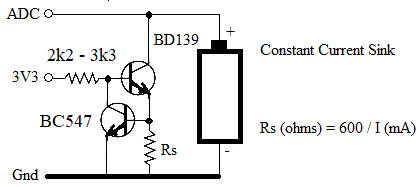 A small heatsink on the BD139 may be needed. Decrease the base resistor to 560Ω to 1kΩ to get Vce down to 0.3V That will give get the cell down to 0.9V before the current tapers off. Edited 2024-03-25 22:56 by phil99 |
||||
| PEnthymeme Newbie Joined: 27/12/2023 Location: United KingdomPosts: 35 |
Thanks all for the input on this - tinkering still in progress. I built a simple constant load with x4 10k resistors in parallel (heat dissipation) - giving 2.5 ohm. And a 4k7 into the Pico. Leaving it running overnight gave this. 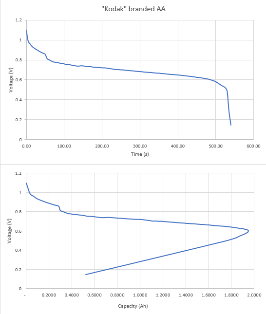 From asking my resident 19yo the voltage / time graph is "easier" to read and she used it to estimate the "life" of the battery at just over 500 minutes - 525 was her "guesstimate". But battery "capacity" is given in mAh - so we calculated that from the data (second chart) - and you can see that this peaks at just shy of 2000mAh (1950mAh from the data) - this occured at 485 minutes, just as the first chart goes non linear. Interestingly Kodak (or whoever actually makes them) produces a data sheet for these batteries and they claim "2800 mAh at 75 Ohms to 0.8 Volts". Ours "failed" at 1950mAh at 0.6V. However, the resistance was less, current higher in our case. But still, quite a bit different. Now, to test this at 75Ohms load. Thanks for the input - for the STEM day will stick with constant "load" for simplicity but will still have a go at the other. Px |
||||
| phil99 Guru Joined: 11/02/2018 Location: AustraliaPosts: 1785 |
An apparent reduction in Ah capacity at higher discharge rates is normal for most battery types as the active material is used less efficiently. Also the internal resistance drops more voltage at higher current, so you reach the end point earlier. Especially for carbon - zinc. As it discharges at higher current hydrogen is produced on one electrode (I forget which), creating an opposing voltage that reduces the terminal voltage. Adding insult to injury, it also raises the internal resistance. Over time the manganese dioxide absorbs the hydrogen and capacity rebounds. If you test it again the next day, at lower current there is still some useful life. |
||||
| JohnS Guru Joined: 18/11/2011 Location: United KingdomPosts: 3659 |
Is the "no load" volatge a good way to check, for each of the common technology batteries (alkaline, NiMH, Li-Ion, ...), or is some sort of small (how much?) load needed? I gather lead-acid batteries can have a "surface charge" which tends to mislead. Is that sort of thing an issue with other technologies? John |
||||
| Mixtel90 Guru Joined: 05/10/2019 Location: United KingdomPosts: 5729 |
The off-load voltage is virtually meaningless unless the battery is severely dead, especially if measured with a sensitive instrument such as a modern digital multimeter. The internal resistance of the cell is what eventually makes it unusable, but it's only a small percentage of the input resistance of the rest meter so it reads almost full voltage until the very end. There are industrial battery monitor relays that use various systems to check the battery condition. Usually they apply a current spike then time the rise in voltage up to a set point. A good battery will recover quickly. As it ages the time to recover will increase. This method attempts to get round the internal resistance problem to some extent and test the battery chemistry. It's useful for loads like tripping batteries where there is almost no load most of the time and a relatively moderate load during tripping. Lead acid traction cells are usually tested using "discharge checkers" that apply a heavy load while measuring the cell voltage. You can see the terminal voltage fall (and the load resistor start to glow!) if the cell is a bit dicky. Such a cell will read perfectly normal on any normal meter you care to use as the internal resistance is pretty low even on a bad cell. Mick Zilog Inside! nascom.info for Nascom & Gemini Preliminary MMBasic docs & my PCB designs |
||||
| JohnS Guru Joined: 18/11/2011 Location: United KingdomPosts: 3659 |
Thanks, Mick. That explains what I've seen with a DMM (and I was aware of the hefty currents used when testing a lead acid battery but thanks for mentioning that). John |
||||
| Volhout Guru Joined: 05/03/2018 Location: NetherlandsPosts: 3532 |
Rechargable batteries can betested that way, and decissions can be made on battery quality. The question was about a test method for Alkaline AA cells. These are not rechargable, and despite the fact that a load test will give you information about the internal resistance, you will not throw it away. You will use it anyway. For a single use Alkaline battery you can very well measure the "no load" voltage to see where in it's life cycle it is. I do this all the time with my grandchildrens toys. 1.6V..1.5V ->perfectly usable battery. 1.4V..doubt. 1.3V and lower->replace. Volhout PicomiteVGA PETSCII ROBOTS |
||||
| twofingers Guru Joined: 02/06/2014 Location: GermanyPosts: 1133 |
This is exactly how I do it!  Regards Michael |
||||
| Mixtel90 Guru Joined: 05/10/2019 Location: United KingdomPosts: 5729 |
Measuring off-load voltage is reasonably ok for rechargeable cells because the internal resistance is much lower than it is for a primary cell. NiCd and lithium types have a long, shallow, almost linear discharge slope until just before they are due to fail, then the slope steepens very sharply. Rather like the first of the "Kodak" curves shown above, but without the high starting voltage. In this case the terminal voltage gives a reasonable estimate of the remaining capacity, providing you know the end point voltage, as application of a load causes much less volt drop across the cell's internal resistance. Alkaline cells are a bit of a mix between primary and rechargeable cells, having some characteristics of both types. I've never used rechargeable alkaline cells, but I suspect their curve may be even closer to a "proper" rechargeable cell. Mick Zilog Inside! nascom.info for Nascom & Gemini Preliminary MMBasic docs & my PCB designs |
||||
| NPHighview Senior Member Joined: 02/09/2020 Location: United StatesPosts: 192 |
A friend of mine designed the battery tester for Bear Automotive when we both worked there in the 1990's; I'll check to see if he can share his testing methodology. I did find a couple of other resources for you: https://batteryuniversity.com/article/battery-test-methods (appropriate level of detail for your young students) https://batterystandards.info/sites/batterystandards/files/draft_white_paper_test_methods_for_battery_understanding_v3_0.pdf (way too detailed for them, but may inform your understanding and cautions) Live in the Future. It's Just Starting Now! |
||||
