
|
|
Forum Index : Microcontroller and PC projects : IIC/I2C or not IIC/I2C
| Author | Message | ||||
Chrisk Senior Member Joined: 21/12/2014 Location: AustraliaPosts: 116 |
Hi Folks Just making up a board using a micromite 64+ and I was wanting your thoughts on which display I should choose? eBay has this unit 2004 20X4 Character LCD Module display With/Without IIC/I2C Should I go for the one with or without IIC/I2C. It's not likely I will need to save on I/O inputs. How much different is the program using IIC/I2C as I haven't used this before. Thoughts please. Chris K |
||||
disco4now Guru Joined: 18/12/2014 Location: AustraliaPosts: 844 |
Here is an example of driving via I2C. Driving LCD with I2C interface using a Micromite (>5.3) See the LCD command in the manual for driving using the MMBasic LCD command. Latest F4 Latest H7 |
||||
| Volhout Guru Joined: 05/03/2018 Location: NetherlandsPosts: 3557 |
Hi, The 20x4 LCD is in essence a parallel LCD. And extra circuit, using a PCF8574, can control this LCD through I2C. When you are short on IO pins, use the I2C version (needs 2 pins). When not, the parallel mode may be simpler since all commands for this parallel connected display are already in MMBasic (6 pins minimal). You do not need the code in the example Disco4Now linked to. Volhout Edited 2024-04-22 17:10 by Volhout PicomiteVGA PETSCII ROBOTS |
||||
| Chrisk Senior Member Joined: 21/12/2014 Location: AustraliaPosts: 116 |
Hi Guys Looking at the info that disco4now sent you both have convinced me that as I am not short of pins I will go for the parallel LCD. I have used this and found it to be easy, so why complicate matters. Thank you guys for your advice. Regards Chris K  |
||||
| Amnesie Guru Joined: 30/06/2020 Location: GermanyPosts: 384 |
Hi all, hello disco4now I just tried the code because I run into the issue having not many pins left (picoMiteVGA) and at first it didn't worked (the address was correct) but thankfully it was mentioned in the code that some require a PAUSE. So I gave that a try and bingo; it works. So my driver board (almost certainly a clone) needs the PAUSE. Works just perfect on the PicoMite! Greetings Daniel |
||||
| Volhout Guru Joined: 05/03/2018 Location: NetherlandsPosts: 3557 |
All, One thing to take into account, the I2C interface ia based on a PCF8574 or PCF8574A I2C port explander. That chip has been around since the invention of I2C. The original Philips PCF8574 chips only accept 100kHz I2C signals. The newer TI parts (and maybe also the NXP parts) are called PCA8574(A) and accept 400kHz I2C. Depending the chineese clones on those boards, or genuine chips, that may be something to try if it does not work. 100kHz will allways work. If you use OPTION SYSTEM I2C, use option SLOW (default = FAST = 400kHz). Volhout Edited 2024-04-22 22:58 by Volhout PicomiteVGA PETSCII ROBOTS |
||||
| Amnesie Guru Joined: 30/06/2020 Location: GermanyPosts: 384 |
Volhout, thanks for this additional information (since I am using System I2C). I copied this info as a comment into my code to remember for those cases if I encounter such problem. Greetings Daniel Edited 2024-04-22 23:17 by Amnesie |
||||
| Amnesie Guru Joined: 30/06/2020 Location: GermanyPosts: 384 |
Hello Again, I created a little I2C adapter board with a 3v3 Level Shifter included. As I am aware, there are no such boards with a 3v3 Shifter available. Maybe someone can use this too. It has the option to use also normal 5V SDA & SCL. 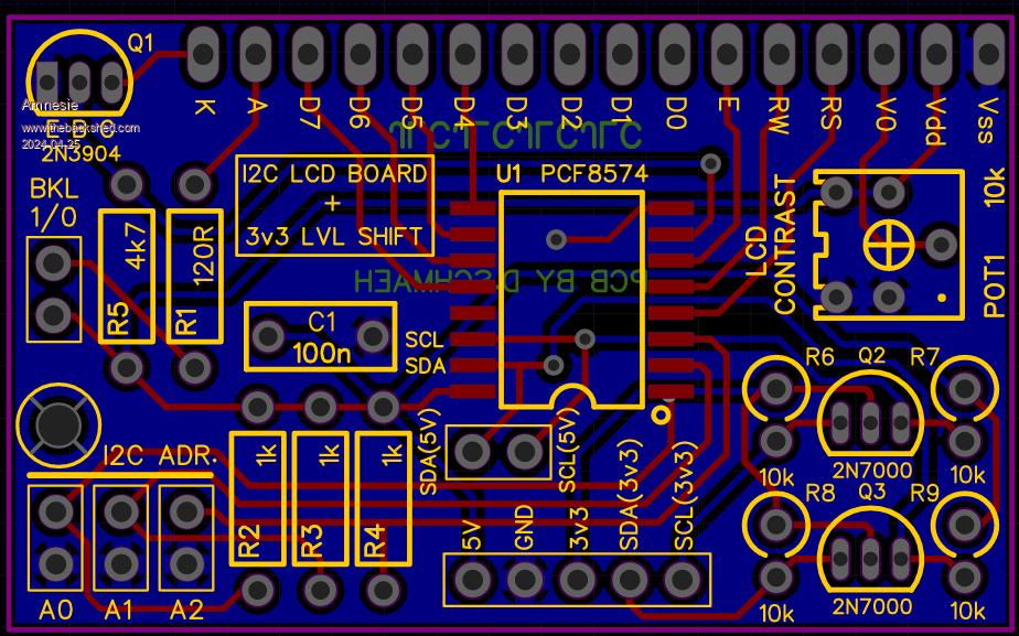  And the Gerbers: Gerber_x_mobile_miniX_lcd_i2c_connector_public_2024-04-24.zip Greetings Daniel Edited 2024-04-25 03:46 by Amnesie |
||||
| Chrisk Senior Member Joined: 21/12/2014 Location: AustraliaPosts: 116 |
Nice work Daniel Where did you get the circuit and is it available. One never knows when it may be useful. Chris K |
||||
| Amnesie Guru Joined: 30/06/2020 Location: GermanyPosts: 384 |
Hello Chris, the circuit is adapted from the original: 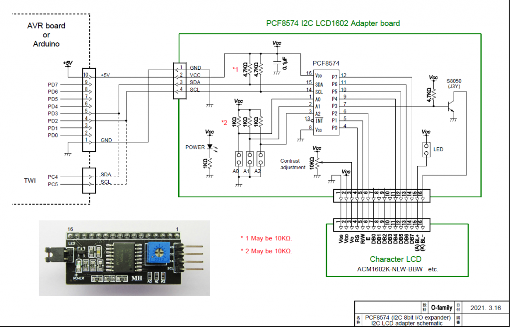 But I have added a level shifter for 3v3 operation, since the picoMite demands 3v3. There is also an additional resistor "R1" (120R) which can be adjusted to your likings, since I found the original is way too bright (and if you don't use PWM this can be a good starting point). Main focus (besides 3v3) was to get rid of all SMD package components... except the PCF8574 of course. I've ordered some @ JLC yesterday and will report back if everything works. But I tripple checked the layout, should be fine. Greetings Daniel |
||||
| JanVolk Regular Member Joined: 28/01/2023 Location: NetherlandsPosts: 96 |
Hello Daniel, I have been using the standard I2C backpannel on 3V3 microcontrollers for years. I only made a modification for the I2C bus. Removed the two resistors from 4K7 and connected two resistors to the I2C bus to the 3V3 if they are not already present on the bus. And replace the LED jumper on the PCB with a 120 ohm resistor(backlight). And if you place the 2004 LCD or 1602 LCD directly (parallel) to the microcontroller, take the 5V into account. You could include 120 ohm resistors (haven't tried yet) in the cables or a level shifter. Jan |
||||
| Amnesie Guru Joined: 30/06/2020 Location: GermanyPosts: 384 |
Hello Jan, this is problematic if I understand you correctly. In fact this was my first idea to work around the level shifter too. BUT: If you look at the datasheet carefully you find: "VIH High-level input voltage 0.7 × VCC (min) VCC + 0.5" (max) This means if you feeding the PCF8574 with Vcc 5V but pulling the SDA & SCL on 3v3 we don't match those requirements: Since: 0.7 * 5V = 3,5 which is minimum needed to recognize it safely as HIGH, but we only have 3,3V. So your attempt may work (or in fact does work since you've tested it) but this relies more on luck / tolerances of the individual chip and manufacturer. I also thought about this, but came to conclusion that it isn't good design practise. And more over: think of the case you don't have good 3,3 Volts but even less... way more out of specs... Don't get me wrong, I believe that it works for you... But it isn't safe. And by a fresh design I also got rid of all (other) SMD components  Greetings Daniel |
||||
| Mixtel90 Guru Joined: 05/10/2019 Location: United KingdomPosts: 5735 |
Feed the 5V through a silicon diode to bring the 3V3 into spec. 0.7 * 4.4 = 3.08 Mick Zilog Inside! nascom.info for Nascom & Gemini Preliminary MMBasic docs & my PCB designs |
||||
| Amnesie Guru Joined: 30/06/2020 Location: GermanyPosts: 384 |
Good idea but wont work if you also want the 5v logic option. You also introduce other problems with the contrast.. so you still need to feed 5v to the contrast then via diode to the chip Vcc and loosing the 5v sda & scl option because now you are out of specs with Vcc + 0,5V (max) on the ViHigh, since 4,4+0,5= 4,9V max on SDA and SCL. I know... I know.. in 99% of all cases this would be ok... but it isn't the right way ... I think the lvl shifter isn't too bad :) |
||||
| Chrisk Senior Member Joined: 21/12/2014 Location: AustraliaPosts: 116 |
Hi Folks Well I didn't expect such a long discussion on what I thought was a simple question. But thanks to all of you that have entered the conversation. Well done (Amnesie) Daniel for pursuing good design practices but the other suggestions also provided simple solutions that can be employed.Chris K  |
||||
| Amnesie Guru Joined: 30/06/2020 Location: GermanyPosts: 384 |
Hello I want to report back that my pcb is fully working, so if you want to order your own, you can do so with the attached gerbers in my initial post (see above). I've ordered an original NXP PCF8574T (no china clones!) and even the datasheet says 100 kHz it works with system i2c @ 400kHz (take this just as an information). But I still have a question: I want to switch the backlight on and off via a Sub but failed. If I edit the "BLmask" from: Dim BLmask = &B00001000 ' Turn on backlighting (P3 = 1) To: Dim BLmask = &B00000000 It is indeed OFF.. But if I want to change it in the running program I failed. I just thought something like: SendCmdByte &B00000000 would do the trick.. but obviously not... Maybe anyone can point me in the right direction! Here is the initial code: ' ----------------------------------------------------------- ' Routines for Micromite to drive serial I2C LCD ' Tested on Explore28 Module running MMBasic V5.3 ' by Andrew Hufer. June 2017 (GTG! TBS Forums) '****************************************************************** ' Originally Adapted from a Maximite I2CLCD program by John Gerrard ' Modified to suit Micromite & Chinese I2C LCD module by Jim Rowe. ' (different connections from PCF8574 to LCD) '****************************************************************** ' 3 subs have been created to make using the routine easier:- ' initLCD - Initialises the LCD Controller ' ClearScreen - Clears the display and sets cursor to line 1 position 1 ' DisplayText row, cursorposition, text$ - which row to output on, repositions cursor to cursorposition, text to be displayed ' Note! The appropriate LCD delays have been inserted in the code but ' have been commented out, as I found that they weren't required on the ' particular 20x4 LCD I was using. If you encounter troubles, uncomment ' the lines as needed to re-enable the delays. ' Remember: Original Philips PCF8574 chips only accept 100kHz I2C signals. Newer ones (by NXP etc) accept ' 400 kHz too. If you use OPTION SYSTEM I2C, use option SLOW (default = FAST = 400kHz). ' LCD functions of PCF8574(A)T I/O bits P0 - P7: ' Name 8574 bit LCD function ' RS = P0 Reg select (pin 4) 0 = Cmd 1 = Data ' R/Wbar = P1 R/W-bar (pin 5, should be 0 for writing) ' EN = P2 EN (pin 6) 0 = Idle, 1 = Active ' BL = P3 Backlight control (Q1 & LCD pin 16) ' DB4 = P4 Data Line 4 (pin 11) ' DB5 = P5 Data Line 5 (pin 12) ' DB6 = P6 Data Line 6 (pin 13) ' DB7 = P7 Data Line 7 (pin 14) ' ---------------------------------------------------------- 'Option AUTORUN ON Option EXPLICIT Option default integer ' Note! Depending on the type of I2C expander used, the I2C address can be different! ' Select appropriate one or create new one accordingly:- Dim As LCDI2cAddr = &H27 ' PCF8574T I2C address A2,A1,A0=1 (&B01001110) All links out 'Dim As LCDI2cAddr = &H3F ' PCF8574AT I2C address A2,A1,A0=1 (&B01111110) All links out ' masks for preparing I2C bytes for writing to 8574 & LCD Dim RSCmask = &B00000000 ' select cmd register (RS = 0) Dim RSDmask = &B00000001 ' or data register (RS = 1) Dim ENmask = &B00000100 ' Enable (active = P2 high) Dim BLmask = &B00001000 ' Turn on backlighting (P3 = 1) Dim CNT(6) ' array to store LCD config command bytes CNT(0) = &B00110011 ' &H33 --> 8-bit / 8-bit mode init CNT(1) = &B00110010 ' &H32 --> 8-bit / 4-bit mode CNT(2) = &B00101000 ' &H28 --> 4-bit mode, 2 lines, 5x7 pixels CNT(3) = &B00001000 ' &H08 --> disp off, cursor off, no blink CNT(4) = &B00000001 ' &H01 --> clear screen, return home cmd CNT(5) = &B00000110 ' &H06 --> increment cursor, cursor move CNT(6) = &B00001100 ' &H0C --> disp on, cursor off, no blink Dim Delay(6) = (0.1, 0.1, 0.06, 0.06, 3, 0.06, 0.06) ' array to store LCD config command byte delay times Dim line1home = &B10000000 ' &H80 --> Place cursor at start of line 1 Dim line2home = &B11000000 ' &HC0 --> Place cursor at start of line 2 Pause 100 ' wait 100ms for LCD to stabilise after powerup 'I2C OPEN 100,100 ' enable I2C (bus speed 100kHz, 100ms timeout) ' since I am using the LCD via SYSTEM I2C there is no need ' to OPEN it InitLCD ' initialise the LCD + controller ' main program loop starts here ' This example was designed for a 20x4 LCD display as a test routine Do ClearScreen DisplayText 1, 0, "1234567890" DisplayText 2, 0, "GoodToGo!!" DisplayText 3, 0, "abcdefghij" DisplayText 4, 10, "zyxwvutsrq" Pause 1000 DisplayText 1, 10, "1234567890" DisplayText 2, 10, "GoodToGo!!" DisplayText 3, 10, "abcdefghij" DisplayText 4, 0, "zyxwvutsrq" Pause 1000 DisplayText 1, 0, "GoodToGo!!" DisplayText 2, 0, "1234567890" DisplayText 3, 0, "abcdefghij" DisplayText 4, 10, "zyxwvutsrq" Pause 1000 DisplayText 1, 10, "GoodToGo!!" DisplayText 2, 10, "1234567890" DisplayText 3, 10, "abcdefghij" DisplayText 4, 0, "zyxwvutsrq" Pause 1000 Loop End ' end of main part of program, subs follow ' ----------------------------------------------------------------- ' subroutine to Display text on LCD. Sub DisplayText row, cursorposition, text$ Local I Select Case row Case 1 sendcmdbyte(line1home + cursorposition) 'row 1 on 16x2, 20x4 LCD panels Case 2 sendcmdbyte line2home + cursorposition) 'row 2 on 16x2, 20x4 LCD panels Case 3 sendcmdbyte(line1home + 20 + cursorposition) 'row 3 on 20x4 LCD panels Case 4 sendcmdbyte(line2home + 20 + cursorposition) 'row 4 on 20x4 LCD panels End Select For I = 1 To Len(text$) SendDataByte Asc(Mid$(text$, I, 1)) Next I End Sub ' ----------------------------------------------------------------- ' subroutine to clear LCD screen Sub ClearScreen SendCmdByte CNT(4) Pause 3 ' pause as per datasheet but may not be necessary due to code delays End Sub ' ----------------------------------------------------------------- ' subroutine to initialise the LCD Sub InitLCD Local I For I = 0 To 6 SendCmdByte CNT(I) Pause Delay(I) ' pause as per datasheet but may not be necessary due to code delays Next End Sub ' ----------------------------------------------------------------- ' subroutine to send a command byte (aByte) to the LCD controller Sub SendCmdByte aByte Local temp, RSbit RSbit = RSCmask ' make sure we're sending to cmd reg (RS=0) ' then prepare the more significant nibble temp = (aByte And &HF0) Or RSbit Or BLmask DirectSend temp ' and send it ' then prepare the less significant nibble temp = ((aByte And &H0F) << 4) Or RSbit Or BLmask DirectSend temp ' and also send it End Sub ' ----------------------------------------------------------------- ' subroutine to send a data byte (aByte) to the LCD controller Sub SendDataByte aByte Local temp, RSbit RSbit = RSDmask ' make sure we're sending to data reg (RS=1) ' then prepare the more significant nibble (from aByte) temp = (aByte And &B01110000) Or RSbit Or BLmask DirectSend temp ' and send it ' then prepare the less significant nibble (from aByte) temp = ((aByte And &H0F) << 4) Or RSbit Or BLmask DirectSend temp ' and also send it End Sub ' ----------------------------------------------------------------- ' subroutine to send a nibble (in temp) to the LCD Sub DirectSend temp temp = temp Xor ENmask ' make EN=1 I2C2 WRITE LCDI2CAddr, 0, 1, temp ' send it with EN=1 Pause 0.004 ' pause for 4us as per PCF8574 Datsheet but not needed due code delays temp = temp Xor ENmask ' now make EN=0 again I2C2 WRITE LCDI2CAddr, 0, 1, temp ' before sending again End Sub ' ---------------------------------------------------------------- Anyways, here are some pictures of my project with the LCD: 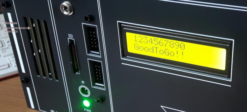 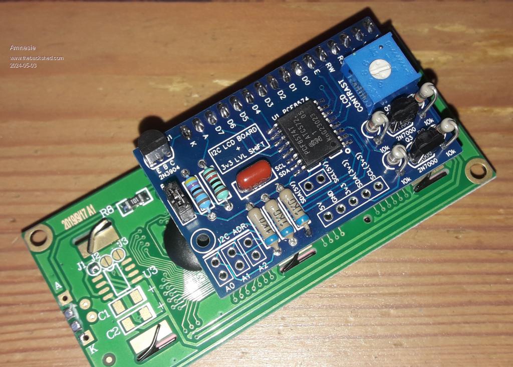 Greetings Daniel Edited 2024-05-03 22:46 by Amnesie |
||||
| Volhout Guru Joined: 05/03/2018 Location: NetherlandsPosts: 3557 |
Nice looking project ! What is it ? IR sensor ? Is it a CMM1 or CMM2 ? Volhout PicomiteVGA PETSCII ROBOTS |
||||
| Amnesie Guru Joined: 30/06/2020 Location: GermanyPosts: 384 |
Hello, it's a a complete adaptive "boot to basic" standalone computer running PicoMiteVGA with built in speaker & amp, I2c-display, IR and PS/2 mouse, which is running on a separate raspberry pi pico (to convert ps/2 to serial). On the back are expansion slots for additional modules like my geiger counter. It is designed to be: - A development environment (GPIO on the front + dust cover) - A fully stand-alone boot to basic with VGA and mouse - A basis for any project x you can imagine... (a lot of space left inside for modules) This way I have a basis for most of my projects without designing a whole new case every time. it is all made of PCB material (excluding the steel enclsoure not in the picture) and highly adaptive due to the vast mounting options. 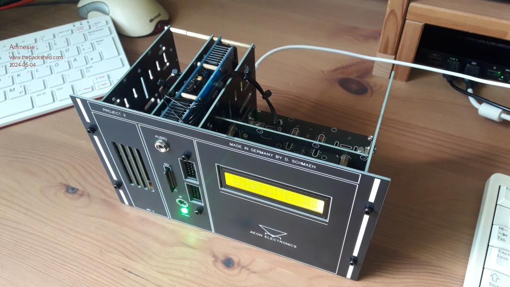  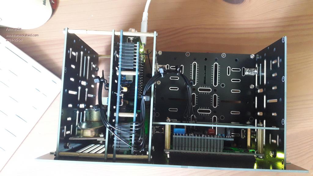 Edited 2024-05-04 00:06 by Amnesie |
||||
| Volhout Guru Joined: 05/03/2018 Location: NetherlandsPosts: 3557 |
Aha Sort of "box of pandorra" It has everything in a nice compact for. So much different from my system. I have a basic PicoMiteVGA unit, and some breadboards and separate pico's.. Oh... and a Game*Mite.... Volhout PicomiteVGA PETSCII ROBOTS |
||||
