
|
|
Forum Index : Microcontroller and PC projects : [Micromite]I2C LCD Library
| Page 1 of 3 |
|||||
| Author | Message | ||||
| G8JCF Guru Joined: 15/05/2014 Location: United KingdomPosts: 676 |
Hi I received the I2C to LCD adaptor on Saturday and have coded up a useful library to make using LCD over I2C using this module as similar as possible to the native parallel LCD commands in MMBasic. What is remarkable is the low price, 99p/US$1.6 including P&P to the UK ! I2C to LCD I/F 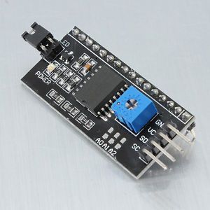
The reduction in wiring is tremendous and most definitely worth 99p. I will be converting my AD9850Controller software over to using this LCDI2C library. Hope someone finds this useful. 73 Peter 'Test suite for LCDI2CLib 'Initialise the I2C LCD device LCDI2C_Init(&H27) WaitForAKey("Press any key for next test") 'Turn On the Backlight LCDI2C_BacklightOn WaitForAKey("Press any key for next test") 'Turn OFF the Backlight LCDI2C_BacklightOff WaitForAKey("Press any key for next test") 'Turn On the Backlight LCDI2C_BacklightOn WaitForAKey("Press any key for next test") LCDI2C 1,3,DATE$ WaitForAKey("Press any key for next test") LCDI2C 2,4,TIME$ WaitForAKey("Press any key for next test") LCDI2C_Clear WaitForAKey("Press any key for next test") DO ' L=TIMER 'DEBUG LCDI2C 1,3,DATE$ LCDI2C 2,4,TIME$ ' PRINT TIMER-L 'DEBUG LOOP END SUB WaitForAKey(Msg$) IF Msg$="" THEN Msg$="Press any key to continue" PRINT Msg$; DO LOOP WHILE INKEY$="" END SUB '----------------------------------------------------------- ------- ' ' LCDI2CLib V1 2014-July-07 ' ' Micromite to LCD using I2C module ' ' (c) Peter Carnegie 2014 ' ' This code is a heavily modified version of I2CLCD.BAS by John Gerrard ' ' ' Uses I2C -> LCD Interface from eBay priced about US$1.50 ' http://www.ebay.co.uk/itm/291116790762?ssPageName=STRK:MEWNX :IT&_trksid=p3984.m1439.l2649 ' http://www.youtube.com/watch?v=wmTWk4Rwfw0 ' ' Uses PCF8574 - 8 bit I2C Port Expander ' I2CAddress is &H27 with unjumpered address pads ' PCF8574 port is wired as follows ' P0 - RS ' P1 - RW ' P2 - EN ' P3 - Backlight On/Off ' P4 - D4 LCD ' P5 - D5 LCD ' P6 - D6 LCD ' P7 - D7 LCD ' Functions in the Library are modelled after the native MMBasic LCD commands ' to ease code conversion ' ' Sub LCDI2C(LineNum,CharPos,Text$) Display string Text$ on LineNum of the display starting at CharPos ' Sub LCDI2C_Clear() Clears the LCD ' Sub LCDI2C_Init(I2CAddr) Initialise the I2C and LCD ' Sub LCDI2C_Close() Close the I2C LCD ' SUB LCDI2C_BacklightOn() Turn LCD backlight ON ' SUB LCDI2C_BacklightOff() Turn LCD backlight OFF ' SUB LCDI2C_CMD(Byte) Send a COMMAND byte to the LCD, ie RS=0 ' SUB LCDI2C_DATA(Byte) Send a DATA byte to the LCD, ie RS=1 ' ' SUB LCDI2C_DirectSend(Byte) Send a BYTE to the LCD - used internally by the lib ' SUB LCDI2C_WireWrite(Byte) Write a byte onto the I2C bus to the LCD ' ' ' Uses 5 Global Variables ' LCDI2C_LCDBackLight, LCDI2C_I2CAddr, LCDI2C_RSDataMask, LCDI2C_EMask, LCDI2C_BackLight ' '----------------------------------------------------------- ------- ' ' Print String to LCD ' ' SUB LCDI2C(LineNum,CharPos,Text$) LOCAL I IF LineNum=1 THEN I=(&H80 + CharPos-1) 'I=&H02 IF LineNum=2 THEN I=(&HC0 + CharPos-1) LCDI2C_CMD(I) FOR I=1 TO LEN(Text$) LCDI2C_DATA(ASC(MID$(Text$,I,1))) NEXT I END SUB '----------------------------------------------------------- ------- ' ' Clear LCD ' ' SUB LCDI2C_Clear() LCDI2C_CMD(&H01) END SUB '----------------------------------------------------------- ------- ' ' INITIALIZE LCD ' ' SUB LCDI2C_Init(I2CAddr) 'Current Backlight state DIM LCDI2C_LCDBackLight LCDI2C_LCDBackLight=0 DIM LCDI2C_I2CAddr LCDI2C_I2CAddr=I2CAddr DIM LCDI2C_RSDataMask 'Select Data register = High P0 on 8574 LCDI2C_RSDataMask=&B00000001 DIM LCDI2C_EMask 'Enable = P2 on 8574 LCDI2C_EMask=&B00000100 DIM LCDI2C_BackLight 'Backlight = P3 LCDI2C_BackLight = &B00001000 'Start I2C I2C OPEN 400,100 '%0011---- %0011---- 8-bit / 8-bit LCDI2C_CMD(&H33) '%0011---- %0010---- 8-bit / 4-bit LCDI2C_CMD(&H32) ' Byte commands - To configure the LCD ' Display Format ' 4bit mode, 2 lines, 5x7 ' ' 001LNF00 ' %00101000 LCDI2C_CMD(&H28) ' L : 0 = 4-bit Mode 1 = 8-bit Mode ' N : 0 = 1 Line 1 = 2 Lines ' F : 0 = 5x7 Pixels 1 = N/A ' Setup Display ' Display ON, Cursor On, Cursor Steady ' ' 00001DCB ' %00001110 LCDI2C_CMD(&H0C) ' D : 0 = Display Off 1 = Display On ' C : 0 = Cursor Off 1 = Cursor On ' B : 0 = Cursor Steady 1 = Cursor Flash ' Setup Cursor/Display ' Inc Cursor Cursor Move ' ' 000001IS LCDI2C_CMD(&H06) ' I : 0 = Dec Cursor 1 = Inc Cursor ' S : 0 = Cursor Move 1 = Display Shift LCDI2C_CMD(&H01) 'Turn Off LCDBacklight LCDI2C_BackLightOff() END SUB '----------------------------------------------------------- ------- ' ' Close the I2C LCD ' ' SUB LCDI2C_Close() 'Close the I2C Bus I2C CLOSE END SUB '----------------------------------------------------------- ------- ' ' Turn Backlight On ' ' SUB LCDI2C_BacklightOn LCDI2C_LCDBacklight=LCDI2C_Backlight LCDI2C_WireWrite(0) END SUB '----------------------------------------------------------- ------- ' ' Turn Backlight Off ' ' SUB LCDI2C_BacklightOff LCDI2C_LCDBackLight=&H00 LCDI2C_WireWrite(0) END SUB '----------------------------------------------------------- ------- ' ' Send Command Byte to LCD ' ' SUB LCDI2C_CMD(Byte) LCDI2C_DirectSend(Byte AND &HF0) LCDI2C_DirectSend((Byte AND &H0F) * 16) END SUB '----------------------------------------------------------- ------- ' ' Send Data Byte to LCD ' ' SUB LCDI2C_DATA(Byte) LCDI2C_DirectSend((Byte AND &HF0) OR LCDI2C_RSDataMask) LCDI2C_DirectSend(((Byte AND &H0F) * 16) OR LCDI2C_RSDataMask) END SUB '----------------------------------------------------------- ------- ' ' Send Byte to LCD over I2C ' ' SUB LCDI2C_DirectSend(Byte) LOCAL B 'Take EN high B=Byte OR LCDI2C_EMask OR LCDI2C_LCDBacklight I2C WRITE LCDI2C_I2CAddr,0,1,B 'Take EN Low I2C WRITE LCDI2C_I2CAddr,0,1,Byte OR LCDI2C_LCDBacklight END SUB '----------------------------------------------------------- ------- ' ' Send Byte over I2C ' ' SUB LCDI2C_WireWrite(Byte) I2C WRITE LCDI2C_I2CAddr,0,1,Byte OR LCDI2C_LCDBacklight END SUB The only Konstant is Change |
||||
| MicroBlocks Guru Joined: 12/05/2012 Location: ThailandPosts: 2209 |
MOBI made something similar with a PIC that works very well too. There is a topic about that here on the TBS. Can you identify the chip that is used, because the price is very low indeed. Microblocks. Build with logic. |
||||
| G8JCF Guru Joined: 15/05/2014 Location: United KingdomPosts: 676 |
@TZAdvantage The I2C board uses a PCF8574 8 bit port expander. I can't even buy the chip for the price they sell and ship the whole module for ! An "intelligent" I2C->LCD module would be preferable, but at 99p (UK currency), this module takes some beating ! I'll search TBS for MOBI's posts. I was/am considering using a PIC18F14K50 as an I2C slave interfacing to an LCD and buttons, but this module is so cheap and so neat in the way it fits onto the back of the LCD board, I don't think I'll bother (except for the fun of programming it up !). 73 Peter The only Konstant is Change |
||||
| atmega8 Guru Joined: 19/11/2013 Location: GermanyPosts: 712 |
Hi, where is the documentation of this converter? |
||||
halldave Senior Member Joined: 04/05/2014 Location: AustraliaPosts: 121 |
what a fantastically documented source code David |
||||
| G8JCF Guru Joined: 15/05/2014 Location: United KingdomPosts: 676 |
@atmega8 There isn't any documentation which I could find. I worked it out by inspection, and by writing test code to find out what went where. Uses PCF8574 - 8 bit I2C Port Expander I2CAddress is &H27 with unjumpered address pads PCF8574 port is wired as follows P0 - RS P1 - RW P2 - EN P3 - Backlight On/Off P4 - D4 LCD P5 - D5 LCD P6 - D6 LCD P7 - D7 LCD 73 Peter The only Konstant is Change |
||||
| G8JCF Guru Joined: 15/05/2014 Location: United KingdomPosts: 676 |
Thank you David, it's only really practicable because of the Auto-Crunch feature in MMEdit which means that comments don't impact the code size as sent down to the uMite. Jim's done a really great job. All we need now are #define's in MMedit to make the code even more maintainable/easy-to-read/smaller ! 73 Peter The only Konstant is Change |
||||
bigmik Guru Joined: 20/06/2011 Location: AustraliaPosts: 2870 |
Gday Peter, All, Maybe its time to announce a new PCB that I have been working on, in conjunction with HallDave and Don, It uses 4 of these chips (which are available for about 50c each) and each have their own, addressable, I2C address.. so a total of 4 I2C addresses on the same board. The Board is designed to bolt onto the back of a 20x4 or 16x4 LCD and has the following `standard' interfaces. And the boards can be cascaded. IC1 LCD IC2 KeyPad 4x4 IC3 8 way LED driver IC4 General IO expansion for users Choice Each PCF8574 comes out to a 10way header with the 8 IO plus GND and 5v (or 3v3 but an LCD need 5v generally) so if you dont want to use the LEDs or other port then you still have access to the IO for other uses.. I am now in the final stages. I am in the tracking and Via minimisation process at the moment. Here is the overlay as it currently stands 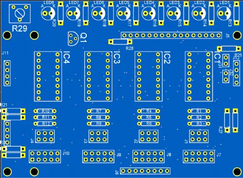
Note the `flea holes' you can see are the vias (I can't seem to turn them off in the view mode without turning the PADs off as well) it is 98mm x 71.4mm approx The LEDS are designed to mount on the backside of the PCB (I havent swapped the overlay to there yet) so that they are directly above the LCD. This board came about as a consequence for another PCB I am desgning, in conjunction with Dave and Don, which I wont announce just yet but is a plug-in for my MuP uMITE PCB, Regards, Mick Mick's uMite Stuff can be found >>> HERE (Kindly hosted by Dontronics) <<< |
||||
| G8JCF Guru Joined: 15/05/2014 Location: United KingdomPosts: 676 |
Hi Mick Looks very promising and all PTH so easy to solder :) I take it that J5 is a direct match for the standard LCD 16 way connector, and that Q1 is for the backlight control ? Will this new module fit within the boundaries of a 1602/2002 display ? Eagerly looking forward to when you have something for sale, bare PCB/fully loaded. Thanks for letting us know Peter The only Konstant is Change |
||||
| halldave Senior Member Joined: 04/05/2014 Location: AustraliaPosts: 121 |
Very easy to solder and should be easy to source bits as well Might be worthwhile getting your chips in as that may be the longest lead time item on these if your going for bare pcb Chips on Ebay |
||||
| G8JCF Guru Joined: 15/05/2014 Location: United KingdomPosts: 676 |
@halldave 10 purchased for 26p (UK) each inc P&P !!! Thanks for the tip 73 Peter The only Konstant is Change |
||||
| bigmik Guru Joined: 20/06/2011 Location: AustraliaPosts: 2870 |
Hi Peter, All, In the design process, I looked at the 16x2 and 20x2 mounting holes. The 16x2 has the pin 1 of the display 8mm from the edge whilst the 16x4 and 20x4 are 10mm from the edge, so mounting holes would overlap... not satisfactory.. so I decided to ignore them, also the 20x2 had a different dual row on the side and was not really usable.. That aside the 16x2 will electrically work and you wont need to screw it down a bit of double sided tape (thicker 3mm stuff) built-up to make sure that the metal work wont short anything on the rear side.. Will be covered in the accompanying manual when it is available.. Regards, MICK Mick's uMite Stuff can be found >>> HERE (Kindly hosted by Dontronics) <<< |
||||
| G8JCF Guru Joined: 15/05/2014 Location: United KingdomPosts: 676 |
Hi Mick I think I understand, from what you say, basically your module will fit on the back of a 1602 LCD module. Double sided foam is fine with me ! What I've found is that the LCD modules have holes in the connector so I have just soldered the I2C i/f module onto the LCD, then used the LCD mounting holes to mount the LCD module against the front-panel. Also, what connections have you configured for the PCF8574 to LCD ? Hopefully as per my code !! Uses PCF8574 - 8 bit I2C Port Expander I2CAddress is &H27 with unjumpered address pads PCF8574 port is wired as follows P0 - RS P1 - RW P2 - EN P3 - Backlight On/Off P4 - D4 LCD P5 - D5 LCD P6 - D6 LCD P7 - D7 LCD Anyway, please let us know when your board will be available. 73 Peter The only Konstant is Change |
||||
| bigmik Guru Joined: 20/06/2011 Location: AustraliaPosts: 2870 |
Hi Peter, As you will find when you buy other `brands' of the module you used, there is NO standard, some are close but others are totally different. I used the pinout as John Gerrard did in his I2C sample.. As, at the time it was the only working example of a working I2C LCD.. Yours is totally different.. Of course this only needs code to be modified to suit. I am not much of a coder so hopefully you can specify each pins connection at the start of the program to allow any derivative to be used. Regards, Mick EDIT **** Sorry the code didnt paste well here is a screen dump 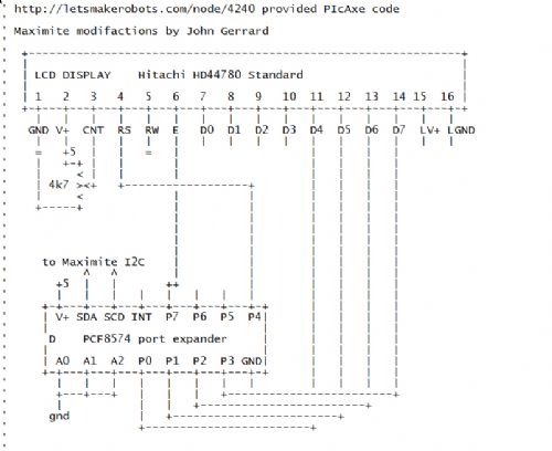
Mick's uMite Stuff can be found >>> HERE (Kindly hosted by Dontronics) <<< |
||||
| bigmik Guru Joined: 20/06/2011 Location: AustraliaPosts: 2870 |
Lads, Designing this PCB has been quite enlightening and I have become very excited by this little chip So I will share a little of what I have learned as it may be useful to others. There are at least two versions of this Chip the 8574 and the 8574a (may only be the NXP brand) The 8574 has 8 possible addresses from 20H-27H the 8574a has 8 from 38H-3FH This device can drive LEDs directly (through appropriate current limiting resistors) BUT drive them with a LOW from the output and the ANODE of the LED connected to Vcc else you will need pull-up resistors to get them to drive properly. The chip is bi-directional and you do not need to tell the chip whether you are reading or writing (No R/W pin) To read a bit from the port, first set the bit high by writing to it and then read back its status. The chip has an INT output that goes low whenever the state of pin (previously SET high) changes state.. This can be used by your micro to trigger an interrupt to let you know something has changed.. Can save polling for say a Keypad. Hope that is helpful information for someone. Regards, Mick Mick's uMite Stuff can be found >>> HERE (Kindly hosted by Dontronics) <<< |
||||
| halldave Senior Member Joined: 04/05/2014 Location: AustraliaPosts: 121 |
I am really excited about this board Two boards cascaded gives you 64 io's Use 1 for LCD 1 for 4x4 keypad You have 8 LEDs to drive individually And then a further 5 x 8 io ports for rtc or flash ram etc Made out of very cheap easy to construct for any newbie parts And the micromite will have all those free ports, also would work for raspberry ip and arduino I cannot find anything out in the internet with this much io extension Wow I can't wait to use it David |
||||
| memberx Newbie Joined: 20/04/2012 Location: AustraliaPosts: 24 |
Hmmmm, have any of you guys used 8574 chips for GP I/O before? One thing to use it as LCD driver and completely another as GP I/O, particularly INPUT. |
||||
| Goeytex Regular Member Joined: 12/05/2014 Location: United StatesPosts: 74 |
The PC8574 I/O expanders are slow and tedious to work with. Its not like you instantly have more I/Os. It takes extra code and constant checking / bit-masking for them to be implemented properly. I avoid them like the plague and would rather spend $50 for a different micro-controller setup than to deal with the complications of working with a PC8574. |
||||
| halldave Senior Member Joined: 04/05/2014 Location: AustraliaPosts: 121 |
According to the data sheet it is designed for general io, however we need to test is out Data Sheet |
||||
| viscomjim Guru Joined: 08/01/2014 Location: United StatesPosts: 925 |
I've been using this one PCA9555. Very simple to use and 16 bits per chip. I have been using this implementation of it for 32 bits of I/O. Lots of fun with uMite. 32bit 2 chip board I2C more more more I used their arduino code to port over to uMite for some simple I/O expansion. Maybe some of this code can be used for keyboard and lcd on the BigI2C. BigMik, nice board. Hopefully between all of us we can put together a real nice "library" for it. Very Exciting!!! Did you use autotrax dex to make that? |
||||
| Page 1 of 3 |
|||||
