Notice. New forum software under development. It's going to miss a few functions and look a bit ugly for a while, but I'm working on it full time now as the old forum was too unstable. Couple days, all good. If you notice any issues, please contact me.
LadyN Guru Joined: 26/01/2019 Location: United StatesPosts: 408
Posted: 10:09pm 04 Feb 2019
Copy link to clipboard
Print this post
I have two questions:
1. is the nanoverter project a method to connect an arduino nano2 to OzInverter 2. what does that achieve?
kanchana Regular Member Joined: 08/05/2018 Location: Sri LankaPosts: 56
Posted: 05:36pm 29 Mar 2019
Copy link to clipboard
Print this post
I want to know the same thingRegards kanchana
tinyt Guru Joined: 12/11/2017 Location: United StatesPosts: 431
Posted: 06:07pm 29 Mar 2019
Copy link to clipboard
Print this post
This is what I know hardware wise for the controller PCB: 1. It can replace the Oztules Control PCB (not the Power Board) 2. Instead of the EG8010 it uses an arduino nano (nano1) and poida's code. 3. You can select from a set of different driver chips for the power mosfets. 4. The second arduino nano (nano2) with poida's code is used to monitor and report/display on an LCD selected operating values. 5. Even though the nano2 controls the startup signal for the nano1, the nano1 can operate without the nano2.
Maybe poida, renewableMark and others can add more.Edited by tinyt 2019-03-31
LadyN Guru Joined: 26/01/2019 Location: United StatesPosts: 408
Posted: 06:46pm 29 Mar 2019
Copy link to clipboard
Print this post
OK, so among other things, the nano board replaces the EG8010 and mirrors its functionality using sPWM like in https://github.com/Terbytes/Arduino-Atmel-sPWM
Hence, instead of the EG8010, we can purchase the power board (with the heatsinks, FETs etc) and pair it with the nanoverter?
tinyt Guru Joined: 12/11/2017 Location: United StatesPosts: 431
Posted: 07:06pm 29 Mar 2019
Copy link to clipboard
Print this post
Yes, but the powerboard interface to the controller has to match with that of the nanoverter which is pin-to-pin equivalent of the oztules control pcb.
renewableMark Guru Joined: 09/12/2017 Location: AustraliaPosts: 1678
Posted: 10:11pm 29 Mar 2019
Copy link to clipboard
Print this post
The nano control card replaces the Oz/Mad control card. It uses a 10 pin ribbon connector/cable to communicate with the Clockman/Oz, or Mad power boards.
The Mad power board uses the totems to operate the fets rather than just directly run from the 2110 chips like the clockman/Oz board does. Oz himself told me it was an improvement on his design, so this is now the go to board.
All the Chinese Ali power boards seem to run from egs002 control cards, which makes them useless to plug into a nano control card.
It's most likely possible to wire them up, but something no one has focused on as the ready made Ali boards aren't really the go to board. First you would have to decipher what the wiring was doing on an Ali board then wire the nano card to fit.
The gerbers for the nano card are in that nano build thread and anyone can get them made, note there is a couple of alterations that need tracks cut/amended.
The Mad power board is his design and you'll need to purchase boards direct from him.
Cheers Caveman Mark Off grid eastern Melb
Warpspeed Guru Joined: 09/08/2007 Location: AustraliaPosts: 4406
Posted: 10:37pm 29 Mar 2019
Copy link to clipboard
Print this post
From memory, some people were experiencing "weird" unexplained and often not repeatable behavior. As the software in the EGS chip is not accessible, its a completely unknown quantity and not exactly trusted by everyone. Including myself.
Later on, some of these problems were tracked down to noise on one or more of the control pins of the EGS, and various band aid fixes suggested. The frequent blow ups continued, and it was felt that "home grown software" might be a lot more trustworthy, or at least fixable if any bugs did surface. It also offers the opportunity to add some extra functionality.
All this has a very long and checkered history. There are multiple problems involved, and some people have been luckier than others in getting these PWM inverters to eventually work reliably.
I don't think anyone has ever assemble one and had it work and run trouble free at the very first attempt ever. And that includes some very knowledgeable and experienced people. Cheers, �Tony.
LadyN Guru Joined: 26/01/2019 Location: United StatesPosts: 408
Posted: 12:33am 30 Mar 2019
Copy link to clipboard
Print this post
Thanks to each of you:
kanchana for bringing this topic up. Since I'm now (and have been) focused on the Warpverter, I completely forgot to followup on this question
tinyt, Mark for the details. I REALLY APPRECIATE the time and input
Tony, with the nanoverter and the rest of your own designed power board you now basically have an OzInverter that does not depend on any 3rd party board, correct?
In other words, there is nothing in your own OzInverter that you cannot develop from scratch (sans nanoverter, which at most you have to program from a blank uC)?
The reason why I ask is because I have seen some boards/modules go unobtanium/obsolete/incompatible on eBay/Aliexpress and I then get into trouble if an older project needs repairs etc
poida Guru Joined: 02/02/2017 Location: AustraliaPosts: 1389
Posted: 01:10pm 30 Mar 2019
Copy link to clipboard
Print this post
The nanoverter project is something that grew from my investigations into PWM pure sinewave inverter control.
Even though the EG8010 chip is cheap and easy to use, I wanted to do it with open source code, running known open hardware.
Numerous MOSFET gate control programs were developed by me. First, I mimicked the EG8010. Later I found another way (thanks Wiseguy for the guide) that is better in a few detail ways and runs at a similar low idle power level. This method is employed in nano1 code. During code development, I posted versions that could perform in novel ways. One version permitted complete control over output AC frequency, varying from 40Hz to 95Hz, via a hand controlled potentiometer. Another version permitted complete control over the PWM frequency, again via hand control pot. where the PWM frequency could go from 40khz to 5 Khz or wider range. All without loosing control of the output AC voltage. Under load too. These strange versions of code allowed me to explore the behaviour of the LC filter in the primary winding, seeing issues in the filter's performance.
The Nanoverter project has evolved into something with many features. The ability to synchronise the output to an external source. The ability via a serial console, to set up over current cut off, under voltage cut off, etc. Th ability to drive MOSFETs directly via the gate drive IC outputs, or to use these outputs to drive totem pole gate drives. When the nanos and gate drive ICs are socketed, repair is simplified after a blowup. I have added data monitoring functions, where we can send a command and receive the DC voltage or DC current, for example, for logging or process control by another computer based controller. (e.g. send "^13" will obtain the DC voltage. Read the code)
I have made a simple adapter cable that plugs into the nanoverter and terminates at a 15 pin 0.1" pin array that I insert into the socket where the EGS002 goes on a Chinese inverter board. And it works perfectly. (Change over from nanoverter to EGS002 takes less than 20 seconds.) This facility permits me to compare and contrast the performance of the EGS002 and the nanoverter board.
We have in the nanoverter, a controller that needs ubiquitous components obtainable from the usual electronics suppliers, running open source code.
The nanoverter board can be built to a partial completion state, omitting the RS-232 support and or mains sync and or nano2 for example. Edited by poida 2019-03-31wronger than a phone book full of wrong phone numbers
kanchana Regular Member Joined: 08/05/2018 Location: Sri LankaPosts: 56
Posted: 09:08am 31 Mar 2019
Copy link to clipboard
Print this post
Really interesting and clever . I have read some where that nanoverter can be synchronized to another inverter so both inverters can share the load. So we can build the step inverter and synchronized it with nanoverter ?Regards kanchana
Tinker Guru Joined: 07/11/2007 Location: AustraliaPosts: 1904
Posted: 09:54am 31 Mar 2019
Copy link to clipboard
Print this post
Yes, that is exactly what I'm planning to do.
Have to wind 4 transformers first though Klaus
renewableMark Guru Joined: 09/12/2017 Location: AustraliaPosts: 1678
Posted: 10:10am 31 Mar 2019
Copy link to clipboard
Print this post
Curious why you want to do that Tinker, since you were happy with the performance of your current units and their wave forms under various loads including microwave.
I personally am worried that the horribly distorted waves may be detrimental to various devices, particularly the newly installed inverter air con.
What's your motive, just a challenge?Cheers Caveman Mark Off grid eastern Melb
Tinker Guru Joined: 07/11/2007 Location: AustraliaPosts: 1904
Posted: 01:17pm 31 Mar 2019
Copy link to clipboard
Print this post
Yep, you got it.
I got 4 working inverters here, a fifth about to be tested and #6 will be the warpinverter. Its a dreadful disease and very contagious. I might call it quits after #6, which should take a while to complete anyway.Klaus
Warpspeed Guru Joined: 09/08/2007 Location: AustraliaPosts: 4406
Posted: 08:50pm 31 Mar 2019
Copy link to clipboard
Print this post
I think its just human nature that any job can be looked back upon in retrospect, and ways can be thought of to have done it better.
I don't think I will start building another inverter, as this one is larger than I really need, worked perfectly from the very first time it was powered up without any changes at all.
And I can think of no way in which I can improve upon it. Its the final distillation of many years of ideas and experimentation. And its quite unique in many different ways.
If/when someone comes up with a microcontroller board, as now seems highly likely, I would certainly love to try that, if it will plug in directly.
But I cannot see myself ever starting another inverter project from scratch, unless this one is destroyed by some unforeseeable natural event. If that happened I would definitely do it all again in the exact same way.Cheers, �Tony.
LadyN Guru Joined: 26/01/2019 Location: United StatesPosts: 408
Posted: 06:12pm 01 Apr 2019
Copy link to clipboard
Print this post
Oh boy!
Does this mean that Warpverters can be built to loadshare among themselves?
So:
1. I could have two 3kWh capable Warpverters (and Warpverters only) and have them be essentially a 5kWh capable Warpverter?
if so, I would really love to know how to do that (because I think right now there is no way to parallel/loadshare Warpverters)!
2. What about being able to series connect Warpverters? (So that they can drive more VOLTAGE): so that I can series connect two 110V Warpverters to get 220V (although I don't know if split phase is necessary so as to emulate the US POWER GRID EXACTLY for most loads)
Warpspeed Guru Joined: 09/08/2007 Location: AustraliaPosts: 4406
Posted: 11:13pm 01 Apr 2019
Copy link to clipboard
Print this post
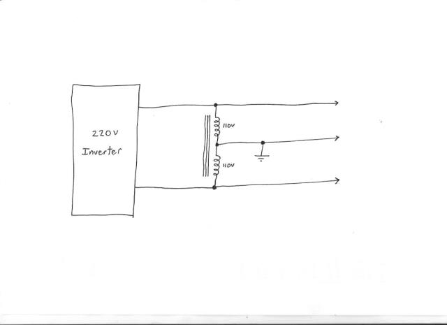
Not sure exactly how the US power system is actually used, but I am assuming that all major loads are 220v, and only minor loads such as some lighting actually use the third neutral wire ?
If that is the case, then just build a 220v Warpverter and split that with a smaller centre tapped inductor to provide the centre neutral connection. The inductor could be made from a standard 110v to 110v isolation transformer.
It would only need to have a power rating sufficient for your minor 110v loads. Most of the load current would not flow through the splitter inductor, only the residual of any load unbalance.
Edited by Warpspeed 2019-04-03Cheers, �Tony.
LadyN Guru Joined: 26/01/2019 Location: United StatesPosts: 408
Posted: 04:42am 02 Apr 2019
Copy link to clipboard
Print this post
Tony,
it uses something called a Split phase. You know more about that than I ever will and I have not looked into it.
What it feels to me is that we can view our power supply as a 220V center tapped transformer and we are all working off one of the taps.
Heavy loads like water heaters, furnace etc use the full windings (=220V) while all the electronics (TV, Computer, fans, lights) use the 117VAC
Now this is where I get confused - they all say it's 117VAC but why is then the full winding 220V?
Sometimes they also say it's 208V.
It confuses me so much that I have kept it aside for later as I am need to work on the warpverter brain for now.
I just wrote this all down in case it can remotely give you an idea
Tinker Guru Joined: 07/11/2007 Location: AustraliaPosts: 1904
Posted: 10:31am 02 Apr 2019
Copy link to clipboard
Print this post
Power (what comes down the wires from the power station) is *not* generated in a transformer but in a 3 phase alternator. Those three phases (at some higher voltage) get then fed into a 3 phase transformer which drop them to the level at your power socket. As the transformer is three phases, the voltage between each phase is x sq root of 3 the voltage between neutral and one phase. Neutral being the common center of the 3 windings(one for each phase) in the transformer.
If you are really curious about this google 3 phase generation and read it better than I can explain it.Edited by Tinker 2019-04-03Klaus


 and very contagious. I might call it quits after #6, which should take a while to complete anyway.