
|
|
Forum Index : Electronics : 24Volt Battery Balancer
| Page 1 of 2 |
|||||
| Author | Message | ||||
| Solar Mike Guru Joined: 08/02/2015 Location: New ZealandPosts: 1124 |
Currently building a couple of systems for 24 volt DC submerged water pumps; the pumps each draw 8 amps when running and > 50 amps on starting; intention is to power the pumps from two series 12v car batteries and charged by two 180W parallel PV 24v panels using a simple PWM controller. To keep costs down, we have a number of (got from the wreckers) 12v car batteries in various conditions and will use these in pairs based on similar capacity. However charging two of these in series because of their indeterminate condition, results in one battery always getting over charged. I need some sort of balancer that will discharge with > 5 amps load to keep them evenly charged. Figured the most simple solution is to sense each batteries charge voltage at the bulk state and place a discharge load across it when bulk is exceeded; this will allow the other battery to get up to bulk, so they both even up. I threw this circuit together as I have these components on hand, its just an accurate voltage reference, comparator that will work with high battery voltages and a mosfet switch plus load resistor; place on a small pcb, one for each battery. Would be interested if anyone has perhaps a simpler solution. 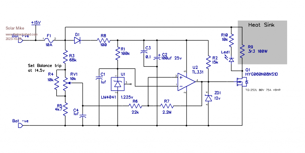 Cheers Mike Edited 2023-10-28 13:27 by Solar Mike |
||||
| phil99 Guru Joined: 11/02/2018 Location: AustraliaPosts: 1790 |
As you have 2 panels another option is to use 2 chargers setup for a 12V battery. One panel and charger for each battery. the V- of one 12V panel / charger / battery system connected to V+ of the other as per normal. Each battery is charged to it's own optimum boost / absorb / float voltages. |
||||
| noneyabussiness Guru Joined: 31/07/2017 Location: AustraliaPosts: 506 |
you could have a simple voltage reference ( zenner simmple or tl431 for fancy ) on the gate of a mosfet ( resistor on drain ), triggered for say 14.3 - 14.5 v that will ensure both batteries will reach optimum full voltage together... sub 5 amp should be a easy dummy load.. k.i.s.s I think it works !! |
||||
| wiseguy Guru Joined: 21/06/2018 Location: AustraliaPosts: 998 |
Why not use a transistor (with heatsink) as the bypass (shunt) load across the battery, that just passes excess charge current through it when your Batt Max is achieved. As an example, say with only 0.5A charge current and one battery is already full it is held at that level and you aren't actually removing any energy from a battery just bypassing the 0.5A excess around it ? A simple max current sense resistor in the emitter with a few parts could set a max limit current if desired. There might be a good reason why not to do this but its not immediately obvious. Edit: On re-reading Noneyas suggestion perhaps this is what he had in mind, but is a shunt resistor needed? Edited 2023-10-29 08:58 by wiseguy If at first you dont succeed, I suggest you avoid sky diving.... Cheers Mike |
||||
| Solar Mike Guru Joined: 08/02/2015 Location: New ZealandPosts: 1124 |
Thanks for the comments, using a transistor or mosfet as a dynamic load to bleed off excessive charge current from the battery would seem like a good idea; I would have to use an op amp to amplify the difference in battery voltage over a given reference, to bias on the load device as required to keep the voltage from increasing. The resultant voltage x current = heat into a heatsink. My miserable stock of silicon transistors is almost non-existent, I do have some genuine 2N3055's 40 years old left over from building CDI ignitions a life time ago. Their SOA ratings would do the job, need something that will handle approx 15 volts across it at min of 5 amps continuous. As these only have a gain of 20ish, a Darlington arrangement would probably work; op amps don't have much current drive. Mosfets on the other hand would be easier to turn on, finding one that will not self destruct with the above load is more difficult, located a couple in my collection that will be ok assuming genuine product, and I think these are. Need to locate a high voltage 12v or above op amp now to drive a mosfet from 0 to approx 8 volts (linear region), will see what I have and draw up another circuit, trouble is I think it will be more complex not simpler. Cheers Mike |
||||
| wiseguy Guru Joined: 21/06/2018 Location: AustraliaPosts: 998 |
Does the circuit need to be any more complex than this ? It can be considered as a precision high power adjustable Zener. After posting realised that the Schematic was for TL431 voltages so have recalculated for the TL431V and posted both. TLV431 is a lower power version of TL431 with better specs but a lower reference of 1.24V instead of 2.495V !   Edited 2023-10-30 09:48 by wiseguy If at first you dont succeed, I suggest you avoid sky diving.... Cheers Mike |
||||
| phil99 Guru Joined: 11/02/2018 Location: AustraliaPosts: 1790 |
Trying to follow the circuit. When Id > 6.6A Q3 turns on supplying base current to Q1. That then applies 12V to the gate of Q2 which blows the fuse. Likewise if Vbat > setpoint = blown fuse. Should Q1 be NPN? |
||||
| wiseguy Guru Joined: 21/06/2018 Location: AustraliaPosts: 998 |
Sorry for the brain teaser Phil, you are quite correct it latches on instead of off . As I said theory circuit warts and all  I will edit one of the schematics and repost, it was just meant to illustrate the programmable nature and connection of the FET without needing opamps etc. It would be better configured to just limit current to the 6.6A and forget the latch - it seemed like a good idea at first. Q1 is correct as PNP as TL431 reaches Vref point it conducts, turning on Q1. The scenario of blowing the fuse at connection, as drawn above would only occur if the battery voltage was already overcharged > for instance the 14.5V desired setpoint. Circuit Rev2 with current limit.... 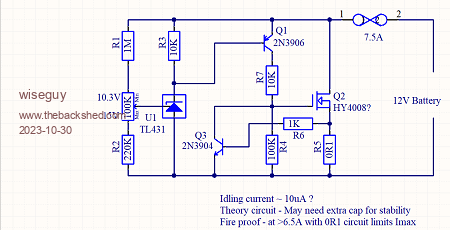 Edited 2023-10-30 10:08 by wiseguy If at first you dont succeed, I suggest you avoid sky diving.... Cheers Mike |
||||
| phil99 Guru Joined: 11/02/2018 Location: AustraliaPosts: 1790 |
Yes, I didn't look at that properly. As Q2 turns on it limits the supply to the reference, thus has negative feedback. As Solar Mike has 2N3055s the circuit could easily be adapted to use one of them with the addition of a NPN driver transistor. Edit A single 2N3055 would overheat so 2 in parallel, each with a 0R22 emitter resistor. 14.5V x 6.5A = 94W 2N3055 P.max = 115W @ 25C case temp. Edited 2023-10-30 12:23 by phil99 |
||||
| KeepIS Guru Joined: 13/10/2014 Location: AustraliaPosts: 1368 |
This is a timely post, I have a similar situation where I need to allow a series bank of LiFePO4 batteries to charge when one of the batteries (for various operational reasons) over time will reach around 94% charge before the others. Especially when doing a bulk charge which I do every few months to ensurer internal BMS equalization. FYI These banks have a 4 pole 10A equalizer across the batteries in each bank, that's fine in theory and works most of the time. Over the past 2 years, for times when things get out of hand, I have been connecting a resistive load across the offending battery to hold it below the internal Dual BMS O-Volt trip point and also bypass the charge current to feed the rest of the bank. Works a treat but it's a PITA and has to be monitored / adjusted as charging current drops. A variable version from 0 to 20A is my design goal, just deciding on which way to go for the variable bypass element with respect to heat, this type of problem usually kicks in when a battery gets above 14.2v in bulk charge mode, the current drops very fast above 14.3v but can be over 40A through the other batteries that are not quite at that point. . Edited 2023-10-30 14:18 by KeepIS It's all too hard. Mike. |
||||
| wiseguy Guru Joined: 21/06/2018 Location: AustraliaPosts: 998 |
Just had another idea.... Turn the wasted FET heat into more charge current for battery with lower potential. A flyback boost circuit would probably be simplest and essentially self regulating. 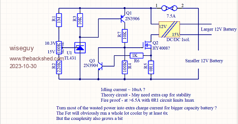 Edited 2023-10-30 14:46 by wiseguy If at first you dont succeed, I suggest you avoid sky diving.... Cheers Mike |
||||
| Pete Locke Senior Member Joined: 26/06/2013 Location: New ZealandPosts: 179 |
Kasyan TV has a simple BMS on their site. This is one I built, and works great across the two batteries I made it for. Easy enough to beef up for higher loading currents. Cheers Pete'. |
||||
| noneyabussiness Guru Joined: 31/07/2017 Location: AustraliaPosts: 506 |
a good cheap dump load at those power levels, try a 3d printer element ( about 6 odd bucks off fleabay) 40 watts, small so will need some sort of cooling if max em out.. mosfet fully turned on running one of these wont dissipate much.. I think it works !! |
||||
| phil99 Guru Joined: 11/02/2018 Location: AustraliaPosts: 1790 |
Taking Wiseguy's idea and circuit diagram the boost converter can be merged with the charge limiter.  Positive AC feedback makes it oscillate when the battery voltage reaches the setpoint. The current limit now sets the peak inductor current so will need to be increased for the same average current. The values of L1, C1, R8 and R9 need to be determined by simulation / experimenting. Too much AC feedback may keep it oscillating when the battery voltage falls. |
||||
| Solar Mike Guru Joined: 08/02/2015 Location: New ZealandPosts: 1124 |
Lots of ideas, Great. I like wiseguy's idea of having a small flyback boost circuit in place of the resistive load; depending on the mismatch state of the two 12v batteries, just to dump up to 100 watts of heat introduces possible reliability problems. Have gone off the idea of using SI transistor as the load heater, 2 devices required per battery, means purchasing some more and unless from a good supplier, I expect most on AliExpress etc are fakes. Plus the heat problem remains. Power mosfets are much cheaper and easier to drive, and I have heaps of those; so I will progress my original circuit and wiseguys design to pcb's with a load resistor that can be swapped out for a flyback load later. Using a flyback converter as the load makes things a lot more efficient, ideally it should be isolated with the output able to connect across the whole battery bank, dumping a higher state charged battery into the bank automatically boosts charge to lower state cells, all battery cells would have the same balance circuit connected to them. I spent some time looking for isolated boost converters that will run off 12v and output 100-200 watts ..... couldn't find any, but there are plenty of current mode flyback controller chips with inbuilt mosfet drivers available, so shouldn't be too difficult to make something. |
||||
| Solar Mike Guru Joined: 08/02/2015 Location: New ZealandPosts: 1124 |
Good idea, maybe tricky to get working efficiently as no proper high current driver used. Prefer to have the same circuit across each battery, so an isolated flyback is required, may also want to use it on a bank of four 12v batteries. |
||||
| wiseguy Guru Joined: 21/06/2018 Location: AustraliaPosts: 998 |
Maybe you could PWM into a capacitive based load and control current with the PWM so the switching device has almost no loss. Not sure how easy but it might also be possible to capacitively transfer energy back to the system or other battery. Sorry I cant devote any more time to the design, much as I would like to, I have other pressing stuff to get done. Phils post was on the same track as my thought progression ie consolidate all into the same circuit but I didnt & I dont have the time available ATM. Edited 2023-10-30 22:03 by wiseguy If at first you dont succeed, I suggest you avoid sky diving.... Cheers Mike |
||||
| Solar Mike Guru Joined: 08/02/2015 Location: New ZealandPosts: 1124 |
I don't have any time also to work on an active flyback or similar load, need to get something basic built first. Here is my take on the proposed circuit using the TL431, delving into my parts bin, have several of the 3 pin smd versions and same with some NPN/PNP small signal transistors. Will make a 100x100 pcb with both versions on it to test. 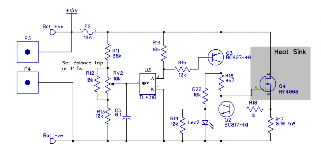 Cheers Mike |
||||
| wiseguy Guru Joined: 21/06/2018 Location: AustraliaPosts: 998 |
Looks like it should work to me. My calculations says adjustment range is a bit high ~ 13.8 - 20.7V trivial change to lower..... Other comment not sure how well the LED will work might, need reduction of R20 value to improve illumination. Edited 2023-10-31 12:30 by wiseguy If at first you dont succeed, I suggest you avoid sky diving.... Cheers Mike |
||||
| Solar Mike Guru Joined: 08/02/2015 Location: New ZealandPosts: 1124 |
Super bright smd leds, 1mA current and they are too bright to look at. (R20 now R21) Here are the PCB layout for both versions, each is 100 x 50mm on a single board, when made 1.2mm thick, easily cut with a craft knife, then snapped in half. There maybe a couple of bypass caps and a ferrite bead on the pcb, not shown in the schematic. For the heat sink, intended to bolt the mosfet \ 100W resistor to a piece of 3mm alloy plate bolted to top of the pcb, perhaps with a 50mm fan for testing; see which version works the best, then do another Ver3. Top:  Bottom: 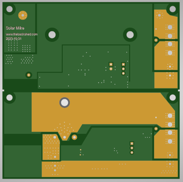 Gerbers: 12Volt_BalModule.zip Cheers Mike |
||||
| Page 1 of 2 |
|||||
