
|
|
Forum Index : Electronics : 24Volt Battery Balancer
| Author | Message | ||||
| noneyabussiness Guru Joined: 31/07/2017 Location: AustraliaPosts: 506 |
nice job... I will be needing something similar very soon so thank you.. I think it works !! |
||||
| Solar Mike Guru Joined: 08/02/2015 Location: New ZealandPosts: 1124 |
Have had a play with the version using the TL431 voltage reference, it didn't work, I had the Anode and Cathode reversed; easily fixed by removing the smd version and soldering on one with thru hole pins.  Once that error sorted, the on\off function was very slow to turn on then off, played around with various components and got it working quite well, Q3 the PNP BC807 wasn't switching cleanly. Here is the final circuit. Will require new pcb if smd components are used. 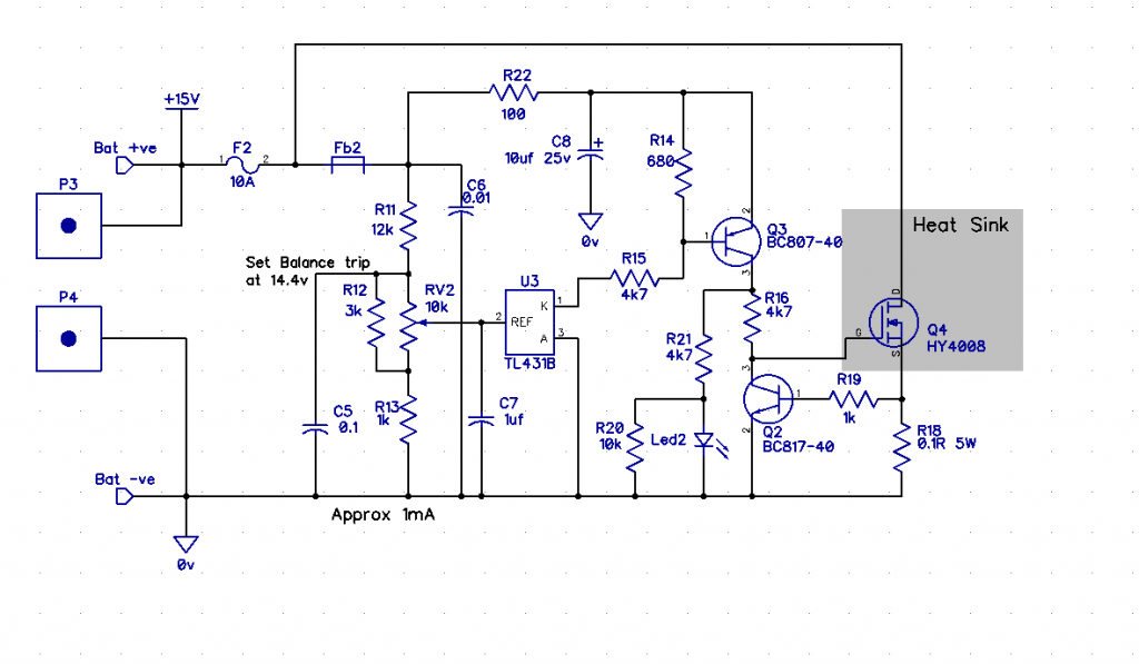 It requires a large Heat sink, if one of the batteries is way different from the other, I'm using two very different sizes in my test, so the smallest capacity one on a deeper discharge will re-charge up faster to a higher voltage - thus requiring the balancer. Think I will visit the local wrecker and get one from their pile, that is physically more similar in size. I am tempted to replace this with a 8pin cpu + mosfet, cost will be the same, this would give me more functionality, to pwm the load according to voltage difference and measure the voltage in the pwm off state, or drive a flyback up-converter to feed the wasted power back into the full bank. Haven't tested the other circuit yet, may not, only require two of these working at the moment. Cheers Mike |
||||
| less_is_more Newbie Joined: 03/04/2023 Location: SpainPosts: 12 |
I found this thread on this very interesting forum I am following since quite a time. As you, I needed to balance two 12V batteries (in my old car and in my future PV system). Not finding anything fitting my needs  , I developped and finished my first proto early this summer. It has been working flawlessly since then on the car, and has resisted quite harsh treatment. , I developped and finished my first proto early this summer. It has been working flawlessly since then on the car, and has resisted quite harsh treatment.Not really a simpler solution, but in any case a cheap and an effective one!: Specs: balances two 12V batteries at <10mV, start/stop current is ~100mA, max seen current is 8A (has overcurrent security), standby current <1mA , a led gives some info (charging, which battery,...) This is the LTspice model I used to simulate the power circuit. 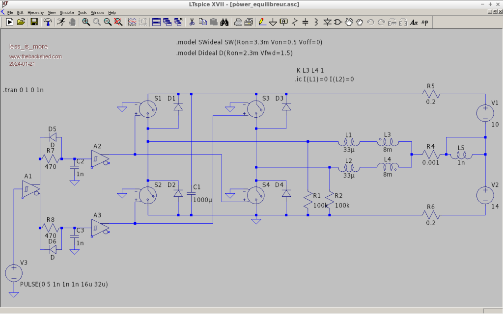 On my prototype, I use this chinese DC motor H-bridge drive with some hacks.  Inductor is a PC SMPS common mode choke used in diferential mode. Brain is a Attiny13A with few components, DC current sensor is a cheap current transformer (really!). Not sure if this fits in this post or if I should open a new one. You decide! |
||||
| Solar Mike Guru Joined: 08/02/2015 Location: New ZealandPosts: 1124 |
Cool, looks like an interesting variation of those common inductive balancers available on AliExpress, except this one works in full bridge mode so may be more efficient. I'm sure many here would like to see more details on your design, perhaps place in a separate post (topic). Cheers Mike |
||||
| Solar Mike Guru Joined: 08/02/2015 Location: New ZealandPosts: 1124 |
Threw this board together, has a dual forward converter, one for each battery; all 4 windings 10 turns each wound on the same ferrite ring core. Driven by a common 100 KHz PWM signal just under 50% duty cycle. CPU Picaxe 08M2 starts balancing when total battery voltage reaches a set point, turns on power to the two 12-12-1W psu's than ramps up pwm to 48% duty. Effectively the two battery main windings make a virtual parallel connection, so which ever battery has the highest voltage will charge the other. The other windings are the core resets. Will it work, don't know, have just sent the gerbers away to be made. Gerbers: CB2.zip Top 100 x 100mm:  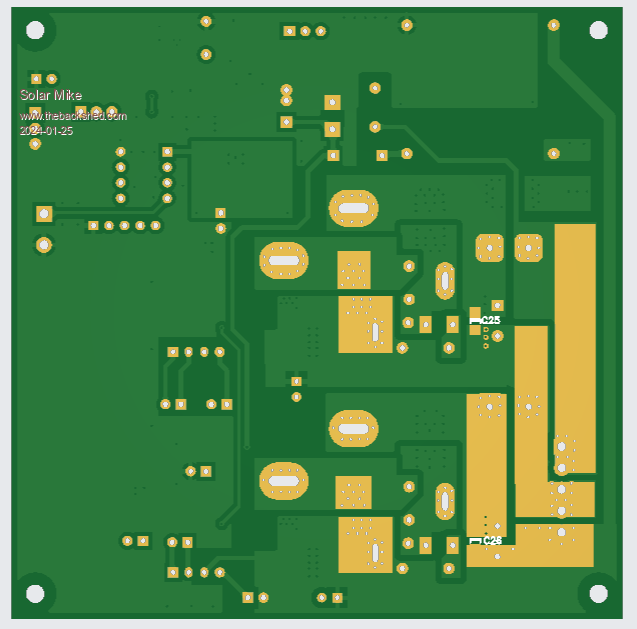 Cheers Mike |
||||
| Solar Mike Guru Joined: 08/02/2015 Location: New ZealandPosts: 1124 |
Have given this a good tryout, using numerous ferrite cores and various turns on each; after destroying several mosfets and a couple of rectifier diodes have got it working quite well on two 12v lead acid batteries in series for 24v. Requires a ferrite core with approx 5uH/Turn^2, I was using 1T\volt, but would probably work better with 8T/12v Some of the blowups were caused by the Picaxe CPU, its pwm output randomly goes haywire if it is turned off when driving the pwm sync output, may switch from 32Khz to 5K or lower as it powers down. Solution is have an external voltage detector "Brown out" on the cpu supply and disable the pwm signals. Its sensitive to resistance of total circuit and wiring to each battery, needs approx 2.5 - 4mm^2 battery leads and similar for the inductor main windings. The pcb now requires changing to suit the changes required. But as this was just a test setup I wont be progressing the design any further as a 2 battery balancer. I have designed a new 8 battery cell modular circuit and will publish that in another topic. Here is the final schematic for each balancer (6v cells). 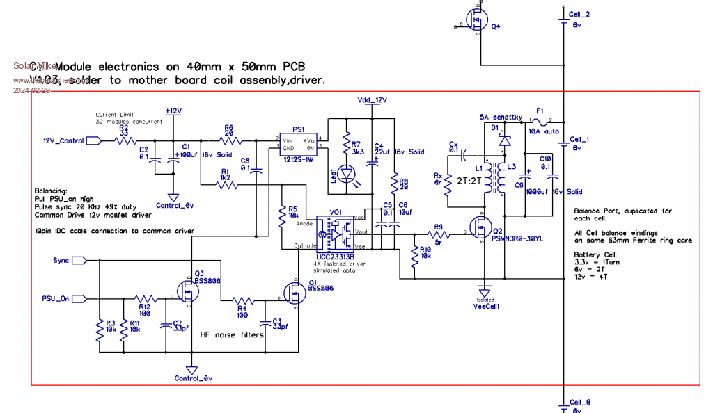 Cheers Mike Edited 2024-02-29 13:04 by Solar Mike |
||||
| Solar Mike Guru Joined: 08/02/2015 Location: New ZealandPosts: 1124 |
Got a call from the site yesterday, system has stopped working, F..Me, some ^%%$&&^% ass has climbed up the nearly 3 meter set of poles the the three 185w 24volt PV panels were installed and made off with two of them, left the other unbolted sitting on the alloy rails, luckily the wind didn't blow it off and smash on the ground. The PV panels were 10 years old, been sitting in my shed for years, really worth nothing to sell to some sh*t head dealer, they went to a lot of effort to remove them. Luckily the electronics were not touched. They must have had the correct Allen key to undo the clamps and the clippie tool to get the PV lead connectors apart, not your usual tools these people carry. Guess I will mount some more and pour epoxy into the Allen head bolt socket heads so its impossible to remove them. Any idea's how to prevent your PV panels being nicked.... electric fence wires running up the poles etc may also be in order. Cheers Mike |
||||
| KeepIS Guru Joined: 13/10/2014 Location: AustraliaPosts: 1369 |
Sorry to hear that, but you/we are left with all the hassle and wasted time. Stinking Arseholes are everywhere. They would likely smash them if they can't remove them It's all too hard. Mike. |
||||
| Solar Mike Guru Joined: 08/02/2015 Location: New ZealandPosts: 1124 |
To date have not replaced the PV panels, waiting for 45mm Z end clamps to arrive, as these are an uncommon size and harder to purchase. The remaining panel they left behind and a 3:1 joiner had their connector clips smashed off, so obviously they didn't have the removal tool to disconnect the cables. Have made a small alarm board with outputs for a siren and Led Strobe lamp + led lights. Inputs for thermal sensor, and two point to point beam sensors + wire trip sensors. Will install this in a covert location, anyone going near the panels will create a lot of action. Made me laugh, the dipstick police person said the panels are too high up and can be seen from the road, should put them at ground level behind the shed (yeah right where the sun won't reach them) Alarm PCB 100x100  Cheers Mike Edited 2024-03-24 17:41 by Solar Mike |
||||
