
|
|
Forum Index : Electronics : Builiding of a complete 6kW PV inverter with MPPT chargers
| Author | Message | ||||
| rogerdw Guru Joined: 22/10/2019 Location: AustraliaPosts: 803 |
I have the impression that there are a lot of these built and being used and I haven't heard of too many issues once people get them going ... and judging from your photos, your work is top class. Mine have only been running a couple of months but are going strong. So far a total of 2,023kWh between the four of them. My MPPT set-up looks like this: *Choke is ???uH (see below) *fets are FDH055N15A x3 *diodes STPS61150CW 150V Schottky 60A (2 x 30A) x 2 *PV open-circuit voltage, at full sun is 111V. *PV pwr 3kW x 4 * caps used, from scrapped Aerosharp Inverters 470uF and 560uF 450V I have four, each handling 3kW of panels and outputting up to 60 amps when conditions are good. I did blow up the 48-12v dc-dc converter amd optocouplers on two of them at the start ... until I worked out you have to discharge the caps before you start mucking around with the board. Whoops. And so far the diodes and mosfets have proved reliable with none having failed. For the inductors I followed Poida's example and used choke formers from wrecked Aerosharps and used 16 turns of 16mm2 on the first ... then 17, 18, 19T on the others as I improved my cramming efforts. I didn't even get around to measuring the uH ... and they can run warm (but I wouldn't say hot) ... but the fan comes on at 40C and runs down to 35C ... and the heatsinks don't get much over ambient. Even on a really hot day the fan keeps them under control. I'd put my money on the circumstances around the small batteries and the switching happening at the same time to have caused your grief. And maybe if higher rated diodes are available you could try them perhaps. Cheers, Roger |
||||
| wiseguy Guru Joined: 21/06/2018 Location: AustraliaPosts: 998 |
Roger, the specs on the ST STPS61150CW diode are pretty good. Maybe Dex should replace his diodes with those based on your experience and if there are still issues copy your (Poidas) chokes. I like the "non repetitive" rating given for parts. I am assuming that does not mean never do it again or it will fail, cause that would mean the first experience damaged/weakened the part. I take it they mean allow sufficient time for any hot spots in the junction to dissipate before hitting it again. The Absolute maximum of 80A RMS per diode is ~ 110A peak For a 10mS sine (non repetitive) it is 500A per diode. So for just the two diodes in one pack they can take a belt of ~1000A for a few milliseconds, which is nearly double the diodes that failed. Given that Mab also recently had a similar MPPT failure - not uncommon for MPPT units (also not uncommon for Victrons with their expired warranty still in sight...) I decided to read up on what makes MPPTs fail to try to find out what part/s are getting stressed. I killed a diode and FET in my unit bench testing a while ago, so I got the sense that maybe MPPT failures might not be rare events, Edited 2024-04-30 18:01 by wiseguy If at first you dont succeed, I suggest you avoid sky diving.... Cheers Mike |
||||
| nickskethisniks Guru Joined: 17/10/2017 Location: BelgiumPosts: 415 |
The higher the input/output ratio the more stress for the diodes. I've run the mppt at 100A charging current limit for years with irfp4110/30cpq100 combo, 2 each, and forced cooling. This was only with 60-62V nominal in and 52-54V out, so high dutcycles. I did had a MOSFET blowup but I suspect actually a PCB fault because of moist and dust build up close to the gate. The board was exposed to my basement environment, allthoug not that bad, but you could see a lot of coroded spots on the PCB. The board transferred 15000kWh of energy before 1 MOSFET failed. I'm now running the same setup(silicon) with newer panels but current is devided over 3 boards now with max of 55A charging current, with 78V in and 52V-55V out. I feel I need to switch to 150V devices but the hardest stressed board did 1100kwh now. |
||||
| KeepIS Guru Joined: 13/10/2014 Location: AustraliaPosts: 1369 |
Most mppt regulators have a recommended input voltage as a ratio to output, go above that and no guarantee it won't fail under high load. I'm not near the manuals at the moment but from memory 1.5 to a max of twice the output for the input voltage. I know that's also suggested for max efficiency in some solar regulators. I've repaired a number of mppt regulators for people, and in every case, re-configuring and dropping the PV output solved the ongoing random failures, and without any loss in available current or efficiency. But that's only my experience, for what it's worth. It's all too hard. Mike. |
||||
| rogerdw Guru Joined: 22/10/2019 Location: AustraliaPosts: 803 |
I reckon someone recommended them somewhere in that epic original mppt build thread by Poida, so that's why I used them. And I didn't fancy trying to reinvent the wheel and experiment with chokes, so I just copied Poida there again ... and it's worked for me so far. I should disconnect one and see what the inductance is and what difference there is between the 16T and 19T ones. It's hard to know just how many have been built and are working away in the background. There always seemed to be people putting their hands up for boards every time there was a batch ordered. Oh okay. Perhaps I'd better tread a bit more carefully with mine. I do have a heap of spare parts and could/should build up another one as a spare perhaps. I did wonder what the limits were, so maybe I was a bit ambitious running mine 3s4p ... maybe I should have stuck to 2s6p ... but so much more wiring!!! Not going to change it though ... too much work to rewire. Haha, I thought I was game going for 60 amps. That's a serious amount of energy collected there, impressive. It's always helpful to know what causes any failures so we can implement improvements ... but even if we don't know for sure ... Poida's initial aim was for us to be able to fix them if they did blow up ... and he has definitely succeeded there. My Voc is 111v but the highest I ever recall seeing as input is 92 volts ... with a 48-60v output Any further panels will come in via ac-coupling so I can have a couple of much higher voltage strings and a lot less wiring. The 6.6kW I put up recently comes in in two strings and are way under the inverter voltage limits. Cheers, Roger |
||||
| -dex- Regular Member Joined: 11/01/2024 Location: PolandPosts: 45 |
Thank you all for your help and valuable information  I checked what is available from my nearest suppliers and I decide to try SiC B2D30065H1 diodes. Its price is only slightly higher than the standard 2x30 dual shotky. I'll use 2 of them for one MPPT. Here is datasheet BASiC-B2D30065H1_Rev_0_1.pdf |
||||
| nickskethisniks Guru Joined: 17/10/2017 Location: BelgiumPosts: 415 |
I don't recommend pushing the current at these 100A levels. It's always a better practice to split this up when possible. I'm using ETD59 cores with as much as copper windings and 100uH. At 40khz. Also something very important is to consider a shorted MOSFET as a big problem, charging current will not be interrupted when end of charge voltage limit is reached. Always build in a secondary relay or equivalent to disconnect the controllers/solar panels when this happens. |
||||
| -dex- Regular Member Joined: 11/01/2024 Location: PolandPosts: 45 |
I tested another MPPT again, with the same diodes as before (I had nothing to do, waiting for new ones  ) and with set of small batteries. Up to about 1.5 kW everything was fine, then my wife turned on the dishwasher and the total consumption was about 2.5 kW. Then MPPT went BANG BANG - it got damaged, but unlike before, it made it even worse - only the mosfet is shorted. This means full voltage from the pv panels on the bus bars - ~100V. Good thing I was nearby and managed to disconnect the batteries, because they were already starting to bubble. ) and with set of small batteries. Up to about 1.5 kW everything was fine, then my wife turned on the dishwasher and the total consumption was about 2.5 kW. Then MPPT went BANG BANG - it got damaged, but unlike before, it made it even worse - only the mosfet is shorted. This means full voltage from the pv panels on the bus bars - ~100V. Good thing I was nearby and managed to disconnect the batteries, because they were already starting to bubble.I see a pressing need for another layer of protection - against too high voltage from a shorted MPPT. Need to protect it when LifePo4 nominally ~51V receives 100V and is charged with an uncontrolled current and the voltage increases. There would have to be a circuit that measures the voltage on the bus bar and, for example, above 65V it disconnects additional the serial relay The lifepo4 battery has a BMS from JK model 200A, but it will not survive when it sees 100V DC at the input, the inverter may also be damaged. It would be best to disconnect the PV inputs, but a good gas-sheathed DC relays (4 pcs for mine) are expensive. So perhaps a good solution would be to disconnect the entire MPPT group. I just don't know what in situation where one MPPT fails, and send high voltage to rest MPPTs outputs Maybe we should also disconnect 12V from them, when one mppt fails. 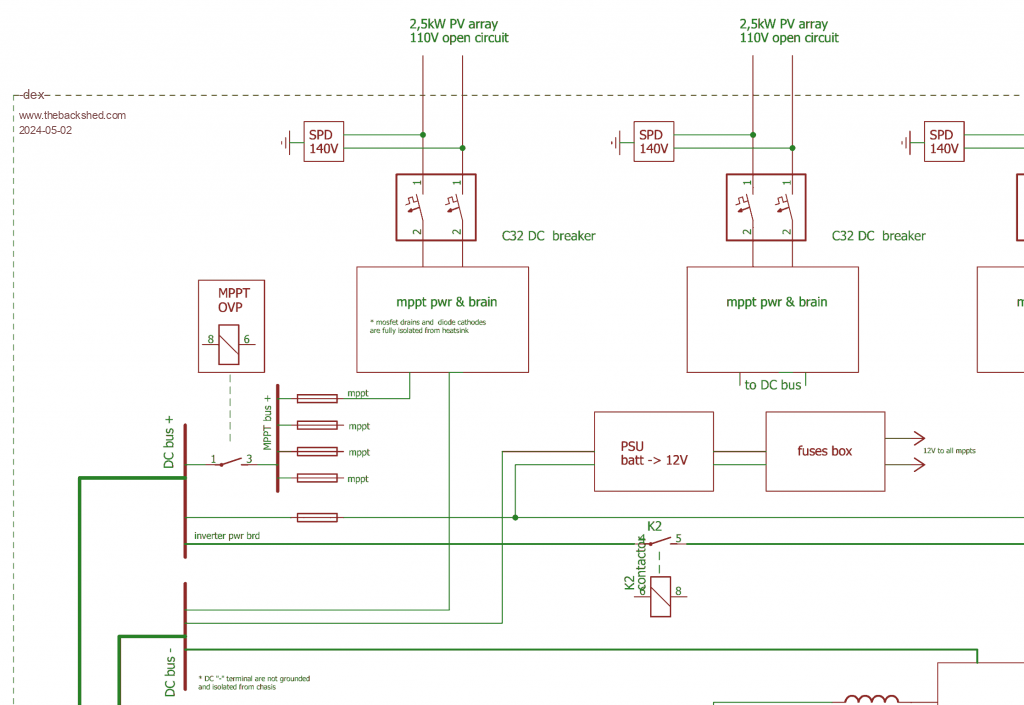 Edited 2024-05-02 18:31 by -dex- |
||||
| phil99 Guru Joined: 11/02/2018 Location: AustraliaPosts: 1790 |
If this is going to be a rare event perhaps simple crowbar protection will do. A suitably rated fuse at each MMPT output gets blown by a SCR triggered by over voltage at the output. To protect the SCR from the peak battery current a series resistor** that limits the current to 2 or 3 times the fuse rating should be in series with it. ** A suitable length of iron wire could be wound around a ceramic bar radiator element. After the fuse has blown it will be absorbing the current from the panels so it will get hot. Eg if the resistor is 0.3Ω and the panels can produce 50A it will dissipate 750W. The ceramic radiator elements are usually 1kW. |
||||
| KeepIS Guru Joined: 13/10/2014 Location: AustraliaPosts: 1369 |
Wonder if the Kilovac Automotive Relay 12-900V High Voltage DC Contactor 500+ A carry, might work, one on each mppt output. I've been using them on the inverter for a long time, have had no trouble breaking 600 A @52v many times, I know your voltage is higher, but might be worth a try as the cost had come way down from what they used to be. That with Phil's suggestion of a beefy SCR and load as worst case scenario backup. Just a thought. It's all too hard. Mike. |
||||
| -dex- Regular Member Joined: 11/01/2024 Location: PolandPosts: 45 |
KeepIS - you said earlier that you have your own lifepo4 packages and a lot of your own experience with them. Can you despair of the scenario of events when, for a battery with a nominal voltage of ~51V, we supply more than twice as much - the question is whether the voltage will immediately be at ~100VDC or it firstly will drop to the battery voltage and slowly increase? |
||||
