Notice. New forum software under development. It's going to miss a few functions and look a bit ugly for a while, but I'm working on it full time now as the old forum was too unstable. Couple days, all good. If you notice any issues, please contact me.
Godoh Guru Joined: 26/09/2020 Location: AustraliaPosts: 379
Posted: 07:35am 02 Mar 2024
Copy link to clipboard
Print this post
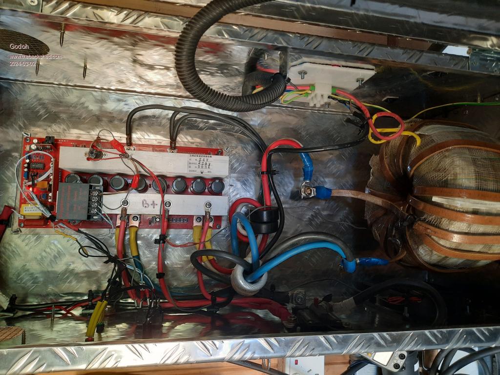
Well today I fired up my new inverter. It runs well and only draws 0.7 amps at idle on my 24 volt system. The transformer is made from two torroids that I unwound and stacked the cores, to give a core of 180mm OD 90mm ID and 100 mm high. the ID turned out to be a bit tight for my build but the turns just fitted on. it is wound for a flux of 1 tesla ( as per the guidance on this site)
The secondary is 225 turns of 2.8mm wire Primary is 12 turns of 12mm x 3.5mm rectangular glass insulated bar.
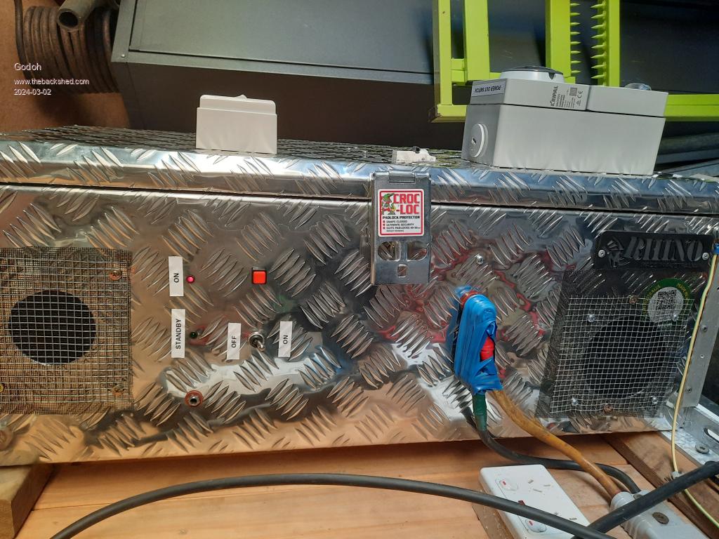
As I said the ID was very tight and I only just fitted the primary in. I have fitted it with one 15 amp outlet and also a single phase 32 amp outlet. As I am using it to charge our EV car I did not want to outlets to be overloaded. My hope is to get it to run at up to 3.5 kw. I may need a second fan at that load but will find out when I hook the car up tomorrow. so far I have run it at 2.4kw and it was very quiet and ran with no problems. Thanks to all the folk here for advice and help Pete
Murphy's friend Guru Joined: 04/10/2019 Location: AustraliaPosts: 584
Posted: 08:04am 02 Mar 2024
Copy link to clipboard
Print this post
Pete's toolbox special , well done.
Wrestling with that 12x3.5mm copper primary would have been fun but it gives you good cooling.
Is that big toroid (check your spelling, funny result if you google it) just sitting there in the box or is it retained by some invisible method?
analog8484 Regular Member Joined: 11/11/2021 Location: United StatesPosts: 89
Posted: 06:13pm 02 Mar 2024
Copy link to clipboard
Print this post
Interesting primary winding. Where did you get the glass insulated bar? Does it have multiple layers?
Godoh Guru Joined: 26/09/2020 Location: AustraliaPosts: 379
Posted: 07:45pm 02 Mar 2024
Copy link to clipboard
Print this post
Hi Mr Murphy, the toroid is just sitting on rubber feet at the moment. The box is actually bolted to the wall, somehow the photos all got rotated when I put them up. So gravity ( there is plenty of weight) is what keeps it there. It is sitting on the bottom of the toolbox, which is reinforced with a piece of 6mm aluminium checker plate.
Analog, the glass insulated bar was sourced from a motor rewinding shop in Launceston. It was last used to rewind a slip ring rotor, I am guessing that he will not use it for a long time. The primary overlaps in the hole but is mostly only one layer on the outside , it is a bit tough to work with but is better at dissipating heat than PVC insulated cables. It cost about $100 for the bar for that transformer. I also bought enough for another one that I have that is wound with 6 x 6mm solar cables in parallel for its primary. I am hoping to reduce the size of that transformer and also get it to run cooler too.
Cheers Pete
Revlac Guru Joined: 31/12/2016 Location: AustraliaPosts: 961
Posted: 08:56pm 02 Mar 2024
Copy link to clipboard
Print this post
Chokes look small.....Compared to the rest of it I like the simple layout in the toolbox. Cheers Aaron Off The Grid
Godoh Guru Joined: 26/09/2020 Location: AustraliaPosts: 379
Posted: 10:13pm 02 Mar 2024
Copy link to clipboard
Print this post
Hi Aaron, yep the chokes are just two small toroids on each leg of the primary. Two turns around each as that is all that would fit. They were the only cores I could find in my shed. I am going to look for some scrapped GTI inverters to see if I can find larger cores. But so far it works great.
What purpose do the chokes actually perform. I am guessing that with the capacitors across the output and the chokes on the input side of the transformer that they are some sort of filter. But how does one know if they are doing what they are supposed to do? The PowerJack inverters that I have pulled apart all had small toroid chokes, just a couple of turns,the ones I see on this site are much larger. I don't have an LCR meter so cannot measure their inductance, maybe I will look into getting a meter sometime
Pete
Revlac Guru Joined: 31/12/2016 Location: AustraliaPosts: 961
Posted: 11:21am 03 Mar 2024
Copy link to clipboard
Print this post
The choke helps lower the idle current, by smoothing some of the high frequency switching, without a choke the current can be relatively high, at least some inductance is better than none so the ones you have probably help. I don't fully understand the workings of it all, as others do. The capacitors help with the 50Hz switching ripple, they do nothing for the high frequency, they don't even see it. It might be worth getting an LCR meter for when you find some more chokes to play with. Cheers Aaron Off The Grid
Murphy's friend Guru Joined: 04/10/2019 Location: AustraliaPosts: 584
Posted: 03:30pm 03 Mar 2024
Copy link to clipboard
Print this post
I do have a LC meter. It does measure the inductance of chokes. But, keep in mind that inductance is frequency dependent and the LC meter operates at a fixed frequency which may be nowhere near the frequency the choke sees in your inverter. So, you can use the LC meter to compare chokes you have but evaluate the measured inductance with what I wrote above.
I also test my chokes for saturation, they should never fully saturate at the highest current spike your inverter experiences. Chokes dampen the effect of current spikes and thus save your mosfets from excessive stress. If you allow them to saturate, then it's like there is no choke at all from there on and your mosfets must be able to handle the peak current or die.
With a steady car charging load you won't get much by way of current spikes but you get plenty when you start compressors or some machinery.
Godoh Guru Joined: 26/09/2020 Location: AustraliaPosts: 379
Posted: 08:43pm 03 Mar 2024
Copy link to clipboard
Print this post
Thankyou Aaron and Mr Murphy for the explanations. When I find some more cores I will make some more chokes and see what effect they have. The new inverter is pretty much just for charging the car, the older inverter is the shed inverter, so far it manages, but it does sound like some larger and more tailored chokes would be good for it too. I would have thought that the inductance of the transformer itself would soak up some of the peaks, but it seems that plenty of people here have enough blown up mosfets to say otherwise. Thanks again for the explanations, and help Pete
Murphy's friend Guru Joined: 04/10/2019 Location: AustraliaPosts: 584
Posted: 09:18am 06 Mar 2024
Copy link to clipboard
Print this post
Hi again Pete. I was just saturation testing some chokes I made and thought you might be interested to see a DSO screenshot and observe what happens when a choke saturates.
The equipment used is just a large capacitor which is charged to a set voltage. This charge is then dumped directly into the choke and a Hall current sensor measures the current resulting.
The screen graduation is 100A per vertical division.
You can see the choke resists the current for the first milli second, allowing it to increase only gradually. After that time the current had risen to about 150A when the trace slope suddenly steepens dramatically. That is the point where the choke starts to saturate and the current can rise as high as the source allows. In this case its about 400A when the capacitor runs out of charge.
For that test the cap was charged to 40V, had I charged it higher then the dumped current would also have gone higher after saturation.
The ring cores you used behave very differently, there is no sharp saturation 'knee'. Instead, the current trace sweeps up quite quickly and, unless you have sufficient inductance, can reach high levels.
On this picture I tested a similar core to yours, using 4 rings and 5 turns of cable.
You can see it reaches 150A in a relatively short time and keeps on climbing.
My chokes are for 48V, the chokes would see double those currents in your 24V system so would saturate at lower power levels. Chokes dampen the current in your primary, they do nothing to the voltage.
Godoh Guru Joined: 26/09/2020 Location: AustraliaPosts: 379
Posted: 08:25pm 06 Mar 2024
Copy link to clipboard
Print this post
Wow pretty impressive waveforms there Mr Murphy. thanks for the effort of setting it all up and posting the traces. Now all we need is for a generic ( if possible) design that will work on most inverters. If that is possible. I will keep my eyes out for more cores, have not had a chance yet. I am still only using the new inverter to charge the car, so no giant surges happening. Thanks again Pete


 , well done.


