
|
|
Forum Index : Electronics : Inverter building using Wiseguys Power board and the Nano drive board
| Author | Message | ||||
| analog8484 Regular Member Joined: 11/11/2021 Location: United StatesPosts: 89 |
Looking forward to test results under real variable load and temperature conditions. It seems even most commercial inverters have issues using only voltage monitoring of lithium batteries. Most of them need true SOC monitoring via closed loop BMS integration to work reliably. Indeed. Kudos on the great progress. |
||||
| KeepIS Guru Joined: 13/10/2014 Location: AustraliaPosts: 1369 |
It depends on how your system is set up. I have over 50kW of LiFePO4 in four switched banks - 12 kW solar. Five solar charges - and independent SOC current monitors per bank - and the list goes on - the system runs 24 - 7 and is almost never switched to mains power. The batteries do not go below 65% and are not charged above 93%, and only get there towards the end of the day where the discharge cycle repeats. Most of what is posted on the WEB is part truth part folk-law and old wives tails, it's irrelevant to my system design parameters. In a system that is running in the sweet spot - everything takes care of itself with little intervention. Finding the sweet spot is the hard part. But separating the truth from the gossip is even harder these days.  It's all too hard. Mike. |
||||
| KeepIS Guru Joined: 13/10/2014 Location: AustraliaPosts: 1369 |
Hi dex, the system is 230V. I also switch the N and EARTH line, but it depends on weather it's switching between full Mains isolation and Solar only, or running the secondary solar/battery power emergency circuit, with separate Mains plus Solar In-feed active. There are two switches, one is manual and is similar, I had it fitted at the Property Fuse box power entry. It's wired as a typical Mains / Generator power changeover switch / isolation. That's designed to allow all existing Earth leakage detection to operate from the Inverter. A normal stand alone ATS has low voltage detection - restart settings etc, and requires a battery voltage connection, and is not (in my case) a true lockout changeover design, even though it uses dual relays. I don't trust it, and others have claimed these can randomly destroy an inverter under certian load conditions. This new unit will be enabled via a 48v 240vac switching relay controlled by the controller mains good port. I have added some test code to also invoke a change over if Inverter AC drops below a preset level for whatever reason (set in settings), this is what I'm currently testing, the controller will normally switch the Mains AC Relay output off when it's commanded to stop, but it might be more complex than that under some load conditions. This setting may not be needed, but that's what the extra testing is for. In any case the option can be disabled in setup, the great thing about the Nano - so much flexibility. Edit: Fixed mistake in text. Edited 2024-04-22 11:32 by KeepIS It's all too hard. Mike. |
||||
| KeepIS Guru Joined: 13/10/2014 Location: AustraliaPosts: 1369 |
Hi, I wanted to add a bit more context as I was heading out when I posted: Any commercial inverter trying to Monitor LiFePO4 SOC with only voltage is obviously crazy! If that is indeed what they are actually trying to do. But like everything - on line forums make these generalized statements, but exactly are they trying to monitor? Like you, I also heard these statements and numerous other half truths and simple throw away lines about LiFePO4 Solar and Inverters. The inverter is simply looking for an accurate voltage where a LFP battery is getting to a low % of charge - Very hard to do if you are aiming at values around 50% to 60% SOC, you can't do this if you don't know the current Load conditions, and it depends on the battery capacity for that load, and the temperature, etc on and on. However this is why these online statements are all generalized white noise to me. If you know your system and power usage, and you know the loads that it will be running under, and you have plotted the discharge cycles over a period of week or months (year in my case), then you know the lowest voltage that the Battery bank will drop to under these running conditions - you can accurately set a low voltage cutoff point for you system. - And that is a simplified statement in itself! Obviously you will know the period of time this "Low voltage measurement" has to persist before initiating an Inverter AC stop condition. The restart voltage is a bigger problem - obviously - and conditions like the Bulk Charge rate that you are subjecting the Battery bank to will drastically affect the ability to determine if the Bank has sufficient charge to be reconnected by voltage state alone. If the inverter shuts down at night - it's not going to recharge from solar, it's not going to turn back on. But that again can be done if you know the system state when charging. How do I answer the question - Yes - my system can work by monitoring voltage alone, but I know exactly what this system does, it records and graphs every current transient, ever voltage fluctuation with load and charge, it records every second of every minute of every hour, 24 hours a day 7 days a week. So the answer is Yes and NO - it depends! It's all too hard. Mike. |
||||
| KeepIS Guru Joined: 13/10/2014 Location: AustraliaPosts: 1369 |
I have added a few LCD screen captures to give an idea of the various information displayed for fault conditions. FYI it's running with USB power connected: These captures are running my Dual Toriod Fan setting. If you don't know why I want this, you might if you build a 3 stack toriod core. I don't need a Heatsink Fan in the main inverter, but in the smaller inverter I will, so I have the option. The first LCD is obvious, F1 on the lower line is indicating that Fan 1 is on for the toriod - if the toriod second fan is triggered, F2 will appear in the last two place markers. The last LCD screen shown the standard inverter code with Heatsink fan and Toriod Fan, TF is obvious, if the Heatsink fan was running, the last two place markers would show HF. There are a few more screens missing that display Software Over current, Toriod and Heatsink Over temp, and AC Enable low voltage cutoff. Most error messages appear on the 3rd line, a couple can appear on the Last line, and the need for a "power cycle" to restart is indicated on the first line. 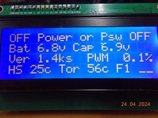 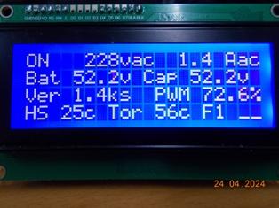 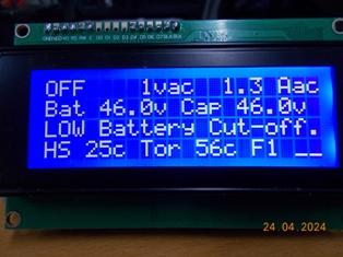  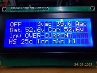  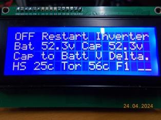 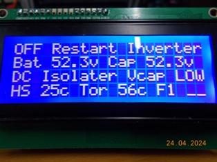  Dual Toroid Fan option  Normal HS and Toriod Fans  BTW The Nano can be programmed via USB with just a tiny program - No IDE or other software or hardware: Simply select the HEX file and hit program, the Nano is ready to go. . Edited 2024-04-24 18:04 by KeepIS It's all too hard. Mike. |
||||
| KeepIS Guru Joined: 13/10/2014 Location: AustraliaPosts: 1369 |
I though I'd run through my error messages and give some idea of things we can do with the Nano. The first message is: "LOW Startup BAT volt" When the inverter is first powered on - the battery voltage should at least be above the Low Battery cutoff setting, if not, you see the messages above and the inverter gives you the middle finger, the LCD top line tells you to "Restart Inverter". "DC Isolater Vcap LOW" At the point of Kilovac enable "for Auto wiring" or, the Main breaker switched to ON and Inverter switched to Run for "manual wiring". At this moment in time, there should be almost no difference between Battery and Cap bank voltage - if there is, you see the above message, possible causes are High resistance / faulty Main breaker or Kilovac wiring or fault, poor inverter wiring etc. "Cap to Batt V Delta" This should never happen unless you have a resistive loss (heat) and this time it's happening under load, so the message above is displayed. It means there is larger voltage drop "Delta setting" between the Inverter battery connections and the Inverter power board Cap bank connections. That could be a wiring fault, terminal connection fault, DC breaker of Kilovac, or other problem. "LOW Battery Cut-off" The battery is below the setting for low battery voltage, this is timed so that short transitions below that point from transient high loads will not trip the inverter, when tripped, the inverter will display the message above, SPWM is ramped down and the inverter waits for the battery restart setup voltage before ramping up and running. "LOW Bat ReStart volt" This message will automatically appear as the battery voltage rises from the previous error above, the inverter will display this until the restart voltage is reached, whereupon the inverter will ramp up and run normally. "LOW AC voltage Trip!" This is mainly to be used with the Software over current setting - NOTE: This has not been fully tested by Poida or myself, it works but can have unforeseen consequences if used incorrectly - Don't use this unless you understand the ramifications for the loads and Inverter without further testing - but I seriously like this and it could be handy if used correctly - to be investigated further. "Software Current ON!" See above error, this indicates that the inverter is varying the PWM duty cycle and lowering the AC voltage to keep the inverter current below the software current setting. The inverter will ramp way down, think Brown Out condition - the Low AC trip above will stop the inverter at the set low AC voltage point. "Toriod C Over-T trip" "Heatsink Over-T trip" Both are obvious, the inverter ramps down and waits for the the inverter to cool down, then ramps back up. "Inv OVER-CURRENT !!!" AC current trip - Hardware OC trip. The over current LED lights, the Reset switch must be pressed to allow the inverter to restart, or the inverter must be powered off and on. Also from DC input current trip using an external current sensor - there is a pin on the controller for this input. "J11 Link = TEST mode" This indicates that the Controller has detected the J11 link is in Test Mode, turn the inverter off before changing the Link. It will be automatically detected and show the message above, or return to normal if the link is removed. In test mode, the Controller will ignore all low voltage conditions - they are not displayed - however it will monitor over temperature settings and will stop SPWM drive until that is resolved. It will Trip on hardware AC over current. It will ramp down on software over current if set, but the LOW AC cutoff is bypassed. Basically the inverter will run from around 13v to 59v. Yes, it will go higher - do you really want to? . Edited 2024-04-25 13:20 by KeepIS It's all too hard. Mike. |
||||
| KeepIS Guru Joined: 13/10/2014 Location: AustraliaPosts: 1369 |
A note on the Nano boards: First, some clones use the MEGA328PB version of the MEGA328P, the PB version has 2 pins 3 and 6 for an extra I2C bus, pins 3 = GND and 6 = VCC in the 328P, apparently some clones with the 328PB have these wired to GND and VCC - so can't be used in any case, as were are not setting these pins as outputs there appears to be no problem with using these boards. I have some of the clone boards with the MEGA328PB, they all work fine: Some Nano boards use the Old boot-loader, some use the new boot-loader, the main difference is the port speed, 115200 baud for the New boot-loader and 57600 baud for the old boot-loader. If you can't program the HEX code into a Nano and it gives a message about not accessing the port or timing out after X retries, it may be a Nano board with the old boot loader, so change the port speed in the Program below: Easy! Here is a link for downloading the program to burn HEX files to the Nano. AVRDUDESS If anyone is interested I can post a Screenshot of the correct settings for the Nano used in the Nano controller. All you need is a PC and the program - no other hardware, it simply plugs into the USB port on the Nano. This is a stand alone program, just download the Portable version for your OS and unzip into a directory. . This will take you to the download page - select portable: AVRDUDESS . Edited 2024-04-25 17:51 by KeepIS It's all too hard. Mike. |
||||
| -dex- Regular Member Joined: 11/01/2024 Location: PolandPosts: 44 |
I have clones with a 328PB chip. I just checked: pin 3 =GND, pin 6=Vcc. In this case, can I use them or not? I run inverter with this chip and seems to be working good, but not tested all functions yet so can't confirm it is 100% fine. I have also 328PA and 328P chips in hand, and they have same as 328PB 3 and 6 pins connected to +V and gnd. |
||||
| KeepIS Guru Joined: 13/10/2014 Location: AustraliaPosts: 1369 |
Yes that seems common, they are not making use of the extra functionally of the chip - I think the 328PB is slightly cheaper so that's likely why it's been used. The inverter code and most nano code does not reassign those pins, so no problems using them as a straight 328P replacement in the Nano board. . Edited 2024-04-25 20:08 by KeepIS It's all too hard. Mike. |
||||
| KeepIS Guru Joined: 13/10/2014 Location: AustraliaPosts: 1369 |
Just a bit of info in case someone else comes across this with a Nano board. I received a few Nano boards today along with a breakout Board for a testing jig I want to make. I tried to program one and it failed - tried the rest and all failed. Tried my existing units with old bootloader and same Ch340 and driver, all good. These used the old boot-loader and CH430 chip, I knew that, which is fine. These were only a few dollars each and the board is really nice - the CPU and components are all correctly marked and as advertised. they are almost identical to the existing boards I have, the exception is these have an SMD semi (FET or TR) next to D13 on the underside. The program error is "cannot set com-state for \\.\COM7", now that gives a hint to the problem, seems the Arduino SW programmer could not initialize the port for a baud rate change, or the response for same was invalid. I tried a terminal program and connected to the Nano without error, so the port is fine, USB is fine no errors. If it was not getting a response to a port baud rate change or bootloader init, then I thought I would try and fool the bootloader by doing the following. 1: I set the baud rate to 9600 with the separate terminal program, connect and immediately disconnected from the board. 2: Hit program on the Arduino IDE - and it worked perfectly and verified - press program again and it has the same initial error. So something wrong with the new boot-loader response in all of them. Repeat Step 1 and it works again for one program verify loop from the IDE. FYI - I'm using the correct CH430 driver version they expressly asked for in the info card that came with the boards. Even downloaded it and installed to verify. Have sent an question and info to seller (in AU) I'll keep the board regardless as they are nice and they work perfectly once programmed. EDIT: Another possibility is a problem with the USB Nano reset bootloader sequence? It's obviously a problem with the boards - That extra SMD has me intrigued, must look at it when I get time. . Edited 2024-04-29 16:42 by KeepIS It's all too hard. Mike. |
||||
| phil99 Guru Joined: 11/02/2018 Location: AustraliaPosts: 1790 |
Quite some years ago I found a sketch on the Arduino site that programs a new bootloader on to a Nano using a Uno as the programmer. It worked well on a couple of cheap Nanos that arrived without the bootloader installed at all. You plug jumpers from the Uno to the 6 pins on the end of the Nano. Can't find it now unfortunately but worth searching for. Edit. This may help Edited 2024-04-29 17:14 by phil99 |
||||
| KeepIS Guru Joined: 13/10/2014 Location: AustraliaPosts: 1369 |
Hi Phil, thanks, yes I know about that one. At the moment I want to keep the programming to a "no extra hardware required" stage. Of course the bootloader is designed for just that purpose with the Arduino IDE and underlying Avrdude SW. If I brick one, that will be the next thing to do, I even have the code ready. I just need to get a suitable device to make one. So many things taking me way to long to do at this time in life  . Edited 2024-04-29 17:05 by KeepIS It's all too hard. Mike. |
||||
| nickskethisniks Guru Joined: 17/10/2017 Location: BelgiumPosts: 415 |
One of my latest Arduino nano purchases has problems with the UART to usb chip, I think some kind of ch340 clones as te marking is scraped off. They don't allow communication at all while working in for instance a mppt controller (to much noise perhaps?) A little bit annoying while in calibration mode or developing phase. Did not see a extra components, I will need to verify that. I'm following the post here with great interest, I hope the teasing will soon stop. 🤪 Are there Gerber's available or do I need to get the boards from wiseguy? Edited 2024-04-29 18:18 by nickskethisniks |
||||
| -dex- Regular Member Joined: 11/01/2024 Location: PolandPosts: 44 |
There is a simpler solution that allows you to upload a new bootloader or a written program without using the bootloader. You need a cheap USBASP programmer as in the photo below. It is compatible with the Arduino environment after instaling USBASP driver, you can programm directly from arduino ide. 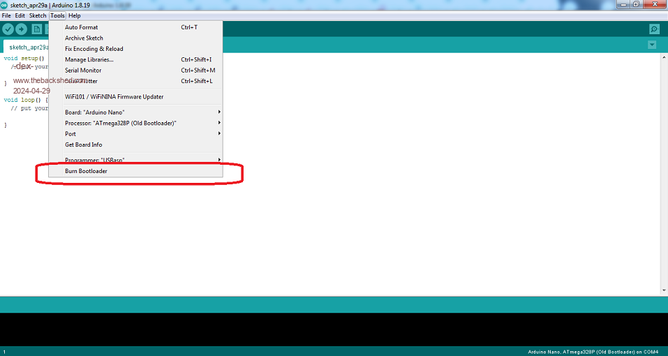  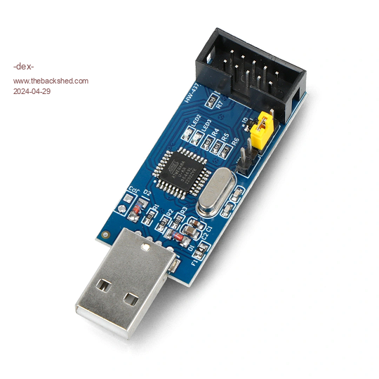 Edited 2024-04-29 18:31 by -dex- |
||||
| KeepIS Guru Joined: 13/10/2014 Location: AustraliaPosts: 1369 |
Hi, I've seen some of those boards, these boards are perfect in communications. I have one of the new boards with CH340 that I programmed by using a method in the previous post, it's running the Inverter perfectly right now. USB com while running, changing Menu settings on the fly with the inverter powering a load, everything is perfect. I think Poida is close to finalizing the official code. I just finished a complete rewrite of my won code for the fourth time. This time char by char and line by line for everything, Inverter control, Menu and LCD drive. I've been throwing everything at it, and just when you think you have every possible fault condition is covered, you find another one out of left field. So anything that is not completely predicted by the code logic, means that I have the logic wrong. So I toss it all and start again with an even better understanding of the interface problem and nuances of the controller electronics interface timing and Nano IO timing. Doing it this way is faster for me, and I always end up having extremely clean code for the little extra effort in doing so. But now there are none!    -- that I can cause or find. -- that I can cause or find.I must say this again. I am amazed at how stable this WG Nano board design is, and how beautifully Poida has got his Core SPWM drive code running - I can't fault it, IMHOP that SPWM core code it a work of art. Boards: I think the boards are about to be ordered, and I recall WG (Mike) said he would confirm board orders? Mike should be back on board pretty soon, he's been extremely busy the past month or so getting things sorted out in another area. Time just gets away from us these days. . It's all too hard. Mike. |
||||
| KeepIS Guru Joined: 13/10/2014 Location: AustraliaPosts: 1369 |
Thank Dex, yes I found the upload bootloader in the IDE before, I'll grab one of those little boards - save me time and effort - thanks. EDIT: It's on the Way. . Edited 2024-04-29 19:12 by KeepIS It's all too hard. Mike. |
||||
| phil99 Guru Joined: 11/02/2018 Location: AustraliaPosts: 1790 |
May not be related but worth checking out. Had one that received data correctly but sending was unreliable. After tracing the circuit between the chips found this:- 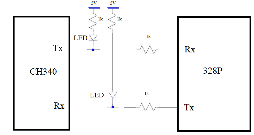 The lower activity LED is on the wrong side of the resistor in the data line. Removing the LED fixed it. |
||||
| KeepIS Guru Joined: 13/10/2014 Location: AustraliaPosts: 1369 |
I did get a response to my findings with a programming problem on the CH340 Nano boards, they are going to test the latest batch of boards and get back to me. The site also has the Nano with FTDI FT232RL chip set. What I liked was how quick the delivery was in just a couple of days. I know you can get some Nano boards for only a few dollars, the boards above are around $12 each for 3, but they are nicely made, and the store do respond quickly to any question or problem, and it's not an automated response in half English, so because of that I'm including the Link to the site, I'm sure it's been mentioned before but, anyway. Web Site - lonely binary BTW thanks Phil for posting that circuit, that is pretty poor, the LEDs in these are at least driven by ports on the USB to serial TTL chip. . It's all too hard. Mike. |
||||
| KeepIS Guru Joined: 13/10/2014 Location: AustraliaPosts: 1369 |
Well the cheap USBASP programmer arrived. Once I had it rewired, I was able to burn a new boot loader or upload a program using it. For program upload the inbuilt IDE software programmer via boot loader is noticeably faster- obviously. The boot loader, the Nano with the old boot loader is now seen as a Nano with the new boot loader, and runs at a faster baud rate accordingly. However, the problem with the these Nano boards remains, it's purely a problem in the hardware or the CH340. I am certain that the CH340 chip will not do anything until it is first connected to at 9600 baud, once connected you then release the port for other programs to use, once you do that, you can leave it sit for hours, it will then connect correctly and the baud rate change handshake responds to the baud request and life is good - it programs and verifies perfectly as before. If you try to program it again - you fail - Why? - because the baud rate is no longer at 9600 after programming, so you can't initialize a new programming cycle, so back to 9600 first. RECAP: These CH340 Nano boards will not respond to a baud rate request at anything other than a 9600 baud connection, after that, they run and program at normal high speed baud rates. Changing the boot loader makes no difference to that behavior. Nice to have the option of installing a new boot loader - or programming without a boot loader, that makes a few extra bytes available for programming. It's all too hard. Mike. |
||||
