
|
|
Forum Index : Electronics : Output Transformer for HV SCC
| Author | Message | ||||
| InPhase Senior Member Joined: 15/12/2020 Location: United StatesPosts: 178 |
I have been working on a high voltage solar charge controller for a while now. Mostly in isolation because it is such a high voltage class that no one wants to touch it. 350 volts DC is the expected max PV input. I had big goals with this beast and have had some good preliminary success (and a lot of failure). Output current at 48 Volts nominal is 100 amps. I decided, for the sake of robustness and control, to use a full H-bridge switching design using 600 V TO-220 IGBTs. I used the same basic isolated gate drive design I used on my inverter. Through trial and error and many exploded IGBTs, I have gotten a working 24 kHz PWM signal to regulate the bridge to produce a 48 volt output from a 350 volt input. My question I want to ask you fellas is about the output transformer secondary winding. Should I use a single large conductor for the 100 amp output, or is there a benefit to using multiple smaller parallel secondaries? Thanks for your time. |
||||
| wiseguy Guru Joined: 21/06/2018 Location: AustraliaPosts: 998 |
There is a method called the current doubling rectifier. You will probably freak when you see the topology but it works a treat. Its advantages are no centre tapped secondary, winding current is half the actual output current. Essentially it is like a 2Phase buck converter where the output voltage is halved and the current is doubled. I have used this for 13.6V at 60+ Amps and 24V at 35A,both with synchronous rectifier FETs. I have tried higher voltages but gave up for diodes due to time constraints. If I remember, the engineer was Laszlo Balogh from Unitrode if you google current doubling rectifier with his name you will find it. In their application schematic they have diodes going to the load and grounded chokes. If you rearrange/swap the circuit so you have grounded diodes and chokes in series with the outputs it makes more sense to understand. It also makes it easy then to substitute the diodes with FETs (and simplifies drive as both FETs are relative to ground) - maybe this is also a possible use for IGBTs, their frequency of operation is half the main transformers fundamental switching frequency. Will be interested in hearing what you think - the bridge approach was a good direction to take IMO. With regard to secondary, at frequencies up to around 80kHz I only ever used single wire and still got efficiencies around mid 90%s+ for synchronous rectifier/fully isolated power supplies (dating back to late 1990s). Edit: I found a pdf for the current doubler rectifier slua121.pdf Although they suggest its use with bridge stage and phase controller it works just as well with voltage or current bridge output control systems. If you swap D1 with L1 and vice versa and turn diode D1 the opposite way, and swap D2 & L2 and turn D2 the other way (anodes to ground) it makes more sense to determine how it works and how to add FETs instead of diodes. Edited 2024-03-05 21:05 by wiseguy If at first you dont succeed, I suggest you avoid sky diving.... Cheers Mike |
||||
| mab1 Senior Member Joined: 10/02/2015 Location: United KingdomPosts: 158 |
Umm... not sure i understand quite how your converter works: Are you driving a 50/60hz transformer using 24khz pwm low freq sinewave? Or using 24khz pwm on a hf transformer? If the latter then you would want to avoid large X section conductors i would think; if the former then they would be ok. |
||||
| InPhase Senior Member Joined: 15/12/2020 Location: United StatesPosts: 178 |
Fascinating circuit for that current doubling rectifier. I've had to read it a few times to get my mind around the theory. Mab, the transformer I currently experiment with is a a high frequency hand wound deal I whipped up with a large ferrite ring from an old CRT television. Going forward, i will need to get many more amps on the secondary. So I thought maybe having one small primary winding of 6 mm² and multiple 6 mm² secondaries, each being independently rectified and filtered and then combined as DC would ease the stress on the transformer. But I also figured that the transformer probably doesn't know if it has one 100 amp winding, or four 25 amp windings, and it probably doesn't care. Since the same energy is transfered, it is magnetically and electrically indistinguishable. Or is it? Or would multiple small completely separate transformers be better? |
||||
| mab1 Senior Member Joined: 10/02/2015 Location: United KingdomPosts: 158 |
The transformer probably won't care if its one 100A winding or 4 x 25A, or 10 x 10A. But my understanding is that with high frequency transformers, you need to avoid large cross section conductors, as you can get eddy currents circulating within the cross section of the conductor. Hence when winding inductors for MPPT controllers you wind n-in-hand of thin magnet wire for preference But I'm no expert so i don't know how the max acceptable section/diameter of the wire relates to frequency. Nor how much difference it actually makes. |
||||
| Solar Mike Guru Joined: 08/02/2015 Location: New ZealandPosts: 1124 |
Here is a graph showing the skin depth of a conductor versus frequency. Your 24Khz equates to approx 0.4mm; If you are using an H-Bridge transformer driver with secondary rectification, most of the current in the wire is AC so skin effect will come into play. Use multiple insulated wires about the 0.8mm dia or thin copper foils for your windings. However during development stripping insulation off the ends of 100 or so copper wires is a real pain, use bigger wire and only do the thin stuff in the final build. In charge controllers with buck converter topology, most of the inductor current is DC, with a smaller HF DC ripple component, so skin effect isn't so much of a factor, just use big fat wires. 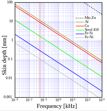 Cheers Mike Edited 2024-03-09 09:04 by Solar Mike |
||||
