
|
|
Forum Index : Microcontroller and PC projects : CMM2: V5.06.00b7 - 3D engine
| Page 1 of 6 |
|||||
| Author | Message | ||||
| matherp Guru Joined: 11/12/2012 Location: United KingdomPosts: 11604 |
V5.06.00b7 http://geoffg.net/Downloads/Maximite/CMM2_Beta.zip This release fixes bugs in sort and incorrect changes made to operators in strings but more importantly is the first beta of a new 3D engine which can make interesting graphics much easier. The new command is DRAW3D and has a number of sub commands. DRAW3D CAMERA DRAW3D CLOSE DRAW3D CLOSE ALL DRAW3D CREATE DRAW3D HIDE DRAW3D HIDE ALL DRAW3D RESET DRAW3D ROTATE DRAW3D SHOW DRAW3D WRITE Before looking at the commands in detail I will try and explain the concept and the limitations of the engine. You can define up to 128 3D objects numbered 1 to 128. Each object is described in terms of how many vertices it has, how many faces it has, which vertices make up each face and the colours of the edges and infill of each face. Objects can have a maximum of 64 vertices and 64 faces. The vertices are specified as x,y,z coordinates referenced to the object centre at 0,0,0 In addition for each object you will define the "camera" that is used to view the object. The 3D engine supports up to 6 camera positions numbered 1 to 6 All cameras look along their Z axis and before you display a 3D object the associated camera must be initialised by defining the x,y position of the camera and its viewplane. In camera terms the viewplane can be thought of as the focal length of the camera lens. So the bigger the value of the viewplane the more the camera "magnifies" the image. For example, if we position a 3D object 1000 units away from the camera and the viewplane is at 200 then the projected image of the object onto the viewplane will be 20% of its original size. If we "zoom" the viewplane to a "focal length" of 800 the projected image will now be 80% of its original size. When a 3D object is created the data used to create it is stored in CMM2 memory and any MMBasic arrays used to create the object can be "erased" if required. All objects are stored in their initial orientation as defined by their initialising data but they can be rotated in three dimensions using the DRAW3D ROTATE command. This command acts upon the initial orientation and stores a rotated copy transparently in the object data internally in the firmware. It is important to understand that every rotation requested for an object starts from the initial orientation and is not cumulative. (however, this can be overridden - see the DRAW3D RESET command) Rotation is specified using a quaternion but don't worry I've included a very simple MATH command to convert yaw, pitch and roll angles into the required quaternion (MATH Q_EULER) Rotation has no effect on a displayed object but merely updates the internal memory definition of the object. There are two commands used to display an object DRAW3D WRITE and DRAW3D SHOW. The only difference is that, assuming the object was already displayed, the SHOW command will clear a rectangle on the current write page sufficient to remove the existing object image before displaying it whereas DRAW3D WRITE just overwrites whatever in on the write page with the 2D representation of the object. It is entirely up to the MMBasic programmer to deal with things like overlap of objects on the screen but to aid this objects that have been SHOWn can be removed and the rectangular area of the screen in which they were drawn cleared using the DRAW3D HIDE command. All objects and camera positions are deleted on any mode change and every time a program is run. For a simple example of a 3D object in action check out this video and I'll attach the code below so you can see how simple it is. Hopefully the above gives you a basic understanding of how the 3D engine works and its limitations. The way the camera works may seem to create a specific limitation in terms of multiple views of an object but we will see in a subsequent post how this can be overcome. The next post will look at the DRAW3D command in detail but in the meantime you can download the firmware and try the two attached example programs. option explicit ]option default float dim integer viewplane = 500 const camera = 1 dim q(4) dim yaw=rad(1),pitch=rad(2),roll=rad(0.5) dim integer nv=9, nf=9 ' cube has 9 vertices and 9 faces 'array to hold vertices dim v(2,nv-1)=(-1,1,-1, �1,1,-1, 1,-1,-1, -1,-1,-1, -1,1,1, 1,1,1, 1,-1,1, �-1,-1,1, 0,0,0) math scale v(),200,v() ' array to hold number of vertices for each face dim integer fc(nf-1) =(4,4,4,4,4,3,3,3,3) dim integer cindex(9)=(rgb(red),rgb(blue),rgb(green),rgb(magenta),rgb(yellow),rgb(cyan),rgb(white),r dim integer fcol(nf-1)=(9,9,9,9,9,9,9,9,9) dim integer bcol(nf-1)=(0,1,2,3,4,5,6,7,8) 'array to hold vertices for each face dim integer fv(math(sum fc())-1)=(1,5,6,2, 1,0,4,5, �0,3,7,4, �5,4,7,6, 2,6,7,3, 0,1,8, 1,2,8, 3,8,2 draw3d create 1, nv, nf, camera, v(), fc(), fv(),cindex(),fcol(),bcol() dim integer c page write 1 draw3d camera 1,viewplane, mm.hres\2, mm.vres\4 do for c=0 to 720 �math q_create roll,1,2,3,q() �draw3d show 1,mm.hres\2,mm.vres\2,1000 �math q_euler yaw,pitch,roll,q() �draw3d rotate q(),1 �inc yaw,rad(1) �inc pitch,rad(2) �inc roll,rad(0.5) �page copy 1 to 0,b next loop draw3d close all[ option explicit option default float dim integer camera_y = mm.vres-20 dim integer viewplane = 700 dim integer camera_z = 0 dim integer camera_x const camera = 1 dim q(4) dim yaw=rad(1),pitch=rad(2),roll=rad(0.5) dim integer nv=6, nf=8 ' octahedron has 6 vertices and 8 faces 'array to hold vertices dim v(2,nv-1)=(0,250,0, � 250,0,0, � -250,0,0, �0,-250,0, � 0,0,250, � 0,0,-250) ' array to hold number of vertices for each face dim integer fc(nf-1) =(3, 3, 3, 3, 3, 3, 3, 3) 'array to hold colours in use dim integer colourindex(8)=(rgb(red),rgb(blue),rgb(green),rgb(magenta),rgb(yellow),rgb(cyan),rgb(bro 'array to hold colour index to be used for lines by face dim integer fcol(nf-1)=(8,8,8,8,8,8,8,8) 'array to hold colour index to be used for fill by face dim integer bcol(nf-1)=(0,1,2,3,4,5,6,7) 'array to hold vertices for each face dim integer fv(math(sum fc())-1)=(0,5,2, �0,1,5, �0,2,4, �0,4,1, �3,2,5, �3,5,1, �3,1,4, � 3,4,2 ) gui cursor on 1,40,mm.vres-20 draw3d create 1, nv, nf, camera, v(), fc(), fv(), colourindex(), bcol(), bcol() draw3d create 2, nv, nf, camera, v(), fc(), fv(), colourindex(), bcol(), bcol() dim integer c page write 1 for c=0 to 720 �camera_x=c+40 �draw3d camera 1,viewplane,camera_x,camera_y �draw3d show 1,mm.hres\4,mm.vres\2,1000 �draw3d show 2,mm.hres\4*3,mm.vres\2,1000 �math q_euler yaw,pitch,roll,q() �draw3d rotate q(), 1, 2 �inc yaw,rad(1) �inc pitch,rad(2) �inc roll,rad(0.5) �gui cursor camera_x,camera_y �page copy 1 to 0,b next draw3d close all Edited 2020-11-29 23:28 by matherp |
||||
| thwill Guru Joined: 16/09/2019 Location: United KingdomPosts: 4370 |
Would it matter if I told you how sorry I was ? Colour Maximite 2 MMBasic Version 5.06.00b7 Copyright 2011-2020 Geoff Graham Copyright 2016-2020 Peter Mather > list "bug.bas" Option Base 1 Option Explicit On Option Default None Dim data$(5) = ("one", "two", "three", "four", "five") Sort data$() Dim i% For i% = 1 To 5 : Print data$(i%) : Next i% > run "bug.bas" four one three two five Order should be "five", "four", "one", "three", "two" I again offer to show you how to use my unit-tests. Kind regards, Tom P.S. I'm sure the 3D stuff is amazing and look forward to someone more talented than me providing Battlezone and Elite ports. Edited 2020-11-30 00:15 by thwill MMBasic for Linux, Game*Mite, CMM2 Welcome Tape, Creaky old text adventures |
||||
| toml_12953 Guru Joined: 13/02/2015 Location: United StatesPosts: 679 |
The file still says b6 at 9:18 am EST 29/11/2020 OK, it's updated now. Edited 2020-11-30 01:53 by toml_12953 |
||||
| thwill Guru Joined: 16/09/2019 Location: United KingdomPosts: 4370 |
From past experience that *may* be your browser having cached the previous version of that zip file, you need to clear your cache. Tom Edited 2020-11-30 00:22 by thwill MMBasic for Linux, Game*Mite, CMM2 Welcome Tape, Creaky old text adventures |
||||
| matherp Guru Joined: 11/12/2012 Location: United KingdomPosts: 11604 |
DRAW3D commands DRAW3D CREATE DRAW3D CREATE nv, nf, camera, vertices(), fc(), faces(), colours() , edge() ,fill() DRAW3D CREATE is the command that creates a 3D object and all the information needed for the object is included in the parameter list. We will use a cube as an example. 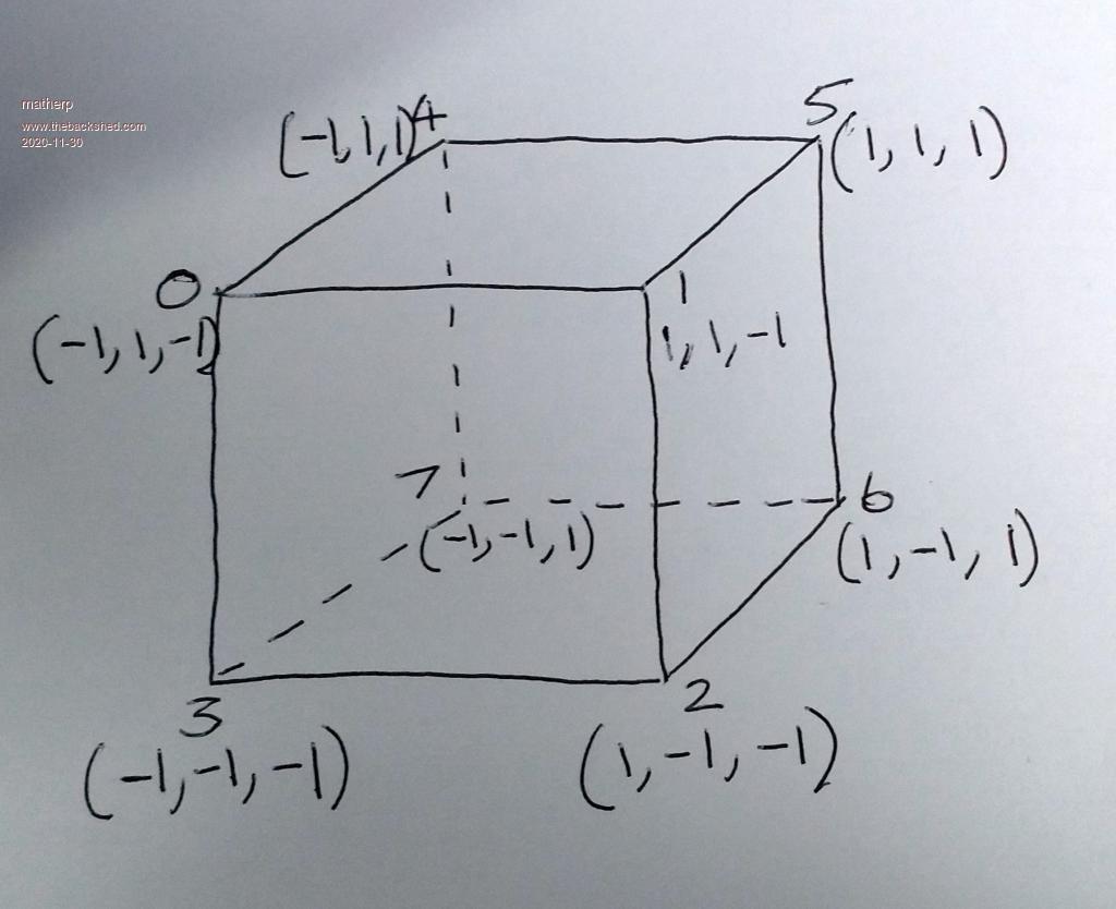 nv: number of vertices (e.g. 8 for a cube) nf: number of faces (e.g. 6 for a cube) camera: number of the camera to use when displaying the object (1 to 6) vertices(): This is a 3 by nv array that holds the x,y,z coordinates of the 3D object. For example the vertex definition for our cube with side length 2 with Option Base 0 centred on 0,0,0 could be: vertices(2,7) = (-1,1,-1, �1,1,-1, �1,-1,-1, �-1,-1,-1, �-1,1,1, �1,1,1, �1,-1,1, �-1,-1,1). Note that the negative values represent the vertices closest to the camera. fc(): is a count of how many vertices are needed to define each face, so in our example for the cube which has 6 faces it would be fc(7)=(4,4,4,4,4,4) faces(): This is a very important array and defines the vertices that make up each face of the 3D object. There is one critical thing in setting up this array. The vertices must be listed in a clockwise order for each face as though you were looking at that face from in front of it. It doesn't matter which order the faces are listed as long as they match the correct vertex count in fc() and it doesn't matter which vertex you start on for each face. In our example this array could be: faces(23)=(0,1,2,3, �1,5,6,2, �0,4,5,1, �5,4,7,6, �2,6,7,3, 0,3,7,4) colours(): This is an array that holds a simple list of all the colours you want to use to colour the 3D object. So if we want a different colour for each face and another one for all the edges we could set this array as follow: colours(6)=(rgb(blue), rgb(green), rgb(yellow), rgb(cyan), rgb(red), rgb(magenta), rgb(yellow)) edge(): This arrays specifies which of our colours to use for each edge of the 3D object. We will set them all to the array index in colours() holding the value yellow edge(5)=(6,6,6,6,6,6) fill(): This array specifies which colour to use for each face of the 3D object. We will set them each to a different colour by specifying the array index into colours() fill(5)=(0,1,2,3,4,5) Those familiar with 3D graphics will notice that the parameters to DRAW3D CREATE exactly match the way 3D objects are defined in .WRL files. For example see the attached is a wrl file downloaded off the web for a dodecahedron. In a later release I may include a command for loading a 3D object directly from a .WRL file but this could easily also be done with a simple MMBasic function. Next post I will look at the other DRAW3D commands and display and manipulate our cube. # �Rikk Carey and Gavin Bell, # �The Annotated VRML 2.0 Reference Manual, # �pages 198-199 # Viewpoint { description "Initial view" position 0.0 0.0 9.0 } NavigationInfo { type "EXAMINE" } # # �A dodecahedron, with 20 vertices and 12 faces. # Transform { �translation -1.5 0.0 0.0 �children Shape { � �appearance DEF A Appearance { material Material { } } � �geometry DEF IFS IndexedFaceSet { � � �coord Coordinate { � � � �point [ � � � � � 1.0 � �1.0 � �1.0, � � � � � 1.0 � �1.0 � -1.0, � � � � � 1.0 � -1.0 � �1.0, � � � � � 1.0 � -1.0 � -1.0, � � � � �-1.0 � �1.0 � �1.0, � � � � �-1.0 � �1.0 � -1.0, � � � � �-1.0 � -1.0 � �1.0, � � � � �-1.0 � -1.0 � -1.0, � � � � � 0.618 �1.618 �0.0, � � � � �-0.618 �1.618 �0.0, � � � � � 0.618 -1.618 �0.0, � � � � �-0.618 -1.618 �0.0, � � � � � 1.618 �0.0 � �0.618, � � � � � 1.618 �0.0 � -0.618, � � � � �-1.618 �0.0 � �0.618, � � � � �-1.618 �0.0 � -0.618, � � � � � 0.0 � �0.618 �1.618, � � � � � 0.0 � -0.618 �1.618, � � � � � 0.0 � �0.618 -1.618, � � � � � 0.0 � -0.618 -1.618 � � � �] � � �} � � �coordIndex [ � � � �1, �8, 0, 12, 13, -1, � � � �4, �9, 5, 15, 14, -1, � � � �2, 10, 3, 13, 12, -1, � � � �7, 11, 6, 14, 15, -1, � � � �2, 12, 0, 16, 17, -1, � � � �1, 13, 3, 19, 18, -1, � � � �4, 14, 6, 17, 16, -1, � � � �7, 15, 5, 18, 19, -1, � � � �4, 16, 0, �8, �9, -1, � � � �2, 17, 6, 11, 10, -1, � � � �1, 18, 5, �9, �8, -1, � � � �7, 19, 3, 10, 11, -1, � � � �] � � �color Color { � � � �color [ � � � � �0.0 0.0 1.0, � � � � �0.0 1.0 0.0, � � � � �0.0 1.0 1.0, � � � � �1.0 0.0 0.0, � � � � �1.0 0.0 1.0, � � � � �1.0 1.0 0.0 � � � �] � � �} � � �colorPerVertex FALSE � � �colorIndex [ 0, 1, 1, 0, 2, 3, 3, 2, 4, 5, 5, 4 ] � �} �} } Edited 2020-11-30 00:40 by matherp |
||||
| matherp Guru Joined: 11/12/2012 Location: United KingdomPosts: 11604 |
In this post we will look at the DRAW3D ROTATE command and the associated DRAW3D RESET command. This rotates one or more 3D objects about their centres. The syntax is: DRAW3D ROTATE q(), n [,n1 [,n2...]} q() is a matrix (quaternion) that defines the required rotation. We use quaternions because they don't suffer from gimbal lock and are computationally fairly efficient but the math is completely hidden by the firmware. The n values are the 3D object IDs assigned when the object was created. From the perspective of the MMBasic user a quaternion is simply a 5 element floating point array and it is loaded using one of two methods MATH Q_EULER yaw, pitch, roll, q() MATH Q_CREATE theta, x, y, z, q() MATH Q_CREATE is documented in the manual and simply defines a rotation around the vector x,y,z by theta degrees (defaults to radians but supports OPTION ANGLE). If x is zero and y is zero then the rotation is around the z-axis which is equivalent to rolling the object. If only x is non-zero then the rotation will pitch the object and y non-zero will yaw the object. MATH Q_EULER is a new command and sets q to perform a rotation as defined by the yaw, pitch and roll angles With the camera facing the object yaw is looking from the top of the object and rotates clockwise, pitch rotates the top away from the camera and roll rotates around the z-axis clockwise. The yaw, pitch and roll angles default to radians but respect the setting of OPTION ANGLE All objects specified in the ROTATE command are rotated by the same amount. Nothing happens on the screen but internally the firmware stores the rotated coordinates as well as the original ones. It is very important to note that the rotate command acts on the original object as defined in the CREATE command. Rotate commands are not cumulative. This ensures that rounding errors can not affect the accuracy. However, there is a command that can override this DRAW3D RESET n [,n1 [,n2...]} This command takes the current rotated version of the object(s) and copies it into the initialisation data. Whilst this isn't recommended for iterative rotations it is very useful in establishing multiple views of the same object. Later in this sequence of posts I will show how to use DRAW3D RESET to create and simultaneously manipulate front and plan views of identical objects |
||||
| qwerty823 Newbie Joined: 30/07/2020 Location: United StatesPosts: 30 |
Peter, Your demos have some truncated lines: dim integer cindex(9)=(rgb(red),rgb(blue),rgb(green),rgb(magenta),rgb(yellow),rgb(cyan),rgb(white),r dim integer fv(math(sum fc())-1)=(1,5,6,2, 1,0,4,5, 0,3,7,4, 5,4,7,6, 2,6,7,3, 0,1,8, 1,2,8, 3,8,2 and dim integer colourindex(8)=(rgb(red),rgb(blue),rgb(green),rgb(magenta),rgb(yellow),rgb(cyan),rgb(bro David |
||||
| matherp Guru Joined: 11/12/2012 Location: United KingdomPosts: 11604 |
In this post we finally get to displaying a 3D object on the screen using the DRAW3D SHOW and DRAW3D WRITE commands. But first it is worth revisiting one aspect of object creation. Our example cube has a side length of 2 so even at 100% it would only cover a maximum of 4 pixels on the screen - not very useful. Luckily there is a simple command we can use to scale the vertices before creating the object. We set up the vertices using: dim float vertices(2,7) = (-1,1,-1, �1,1,-1, �1,-1,-1, �-1,-1,-1, �-1,1,1, �1,1,1, �1,-1,1, �-1,-1,1) We can make the cube the size we want by simply multiplying all the elements in the vertex array by the amount we want. So to make the length of each side 200 we can use: MATH SCALE vertices(), 100.0, vertices() We need to set up the camera specified for the object in the create command before we can display it. To do this we use the command DRAW3D CAMERA n, viewplane, x, y This says position the camera at 3D coordinates x, y, 0 and any 3D objects will project onto an imaginary screen "viewplane" units in front of the camera along the z axis and orthogonal to it. In our world the camera is always at a z position of zero and objects will always be positioned with a positive value of z. In addition the camera will always point directly along the z axis. In future these constraints may change but for efficiency of calculation they make a lot of sense. Up to 6 camera positions may be defined (1 <= n <= 6) and an object will always be displayed using the camera that was defined when it was created. The camera must be configured �using the DRAW3D CAMERA command before any object using it can be displayed. As defined above there are two commands for displaying (rendering) a 3D object: �DRAW3D WRITE and DRAW3D SHOW. The only difference is that, assuming the object was already displayed, the SHOW command will clear a rectangle on the current write page sufficient to remove the existing object image before displaying it whereas DRAW3D WRITE just overwrites whatever in on the write page with the 2D representation of the object. The syntax for both commands is the same so will concentrate on DRAW3D SHOW DRAW3D SHOW n, x, y, z It couldn't get any easier. This says that we want to position the centre of the object at coordinates x, y, z in our virtual 3D world. The camera specified for our object is at a position Xc, Yc, 0. This command projects the object 'n' onto the imaginary screen at "viewpoint" from the camera. The mechanism of projection interprets the relative position of the object in 3 dimensions and does full perspective �compensation taking into account the relative positions of each vertex in three dimensional space relative to the viewplane and the x,y coordinates of the camera. As it displays the object it calculates the screen coordinates of the minimum rectangle into which the rendered object fits. This allows a subsequent SHOW command (but not WRITE command) to erase the previous render and draw the object onto a clean screen. Unlike sprites, 3D objects do not store the background image when the object is written or restore it when the object moves. It is recommended that 3D objects are written onto a blank page and are blitted or page copied (with transparency) onto the background image. Alternatively, putting 3D objects onto page 1 in 12-bit mode with the background on page 0 will work very well. The mechanism of perspective is quite complex but the second example program in the first post shows how the movement of the camera (represented by the cursor at the bottom of the screen) changes the image of the two octahedron with the one nearest the camera bigger than the one further away, the bottom of the octahedron bigger than the top and the side of the octahedron nearest the camera bigger than the side further away. One last point. Neither the x, y positions of 3D objects or the camera positions are constrained by the screen size. In fact they can go from -32766 to + 32766 (0-32766 for Z for the object - the camera is always at z=0). There are lots of combinations where a 3D object will render off the physical display page. This is perfectly acceptable and allow valid objects to exist in the "world" without the constraints of screen space. In the next post I will finish up documenting the remaining DRAW3D commands and build a simple example from our cube. Samples reposted as requested option explicit option default float dim integer viewplane = 500 const camera = 1 dim q(4) dim yaw=rad(1),pitch=rad(2),roll=rad(0.5) dim integer nv=9, nf=9 ' cube has 9 vertices and 9 faces 'array to hold vertices dim v(2,nv-1)=(-1,1,-1, 1,1,-1, 1,-1,-1, -1,-1,-1, -1,1,1, 1,1,1, 1,-1,1, -1,-1,1, 0,0,0) math scale v(),200,v() ' array to hold number of vertices for each face dim integer fc(nf-1) =(4,4,4,4,4,3,3,3,3) dim integer cindex(9)=(rgb(red),rgb(blue),rgb(green),rgb(magenta),rgb(yellow),rgb(cyan),rgb(white),rgb(brown),rgb(gray),0) dim integer fcol(nf-1)=(9,9,9,9,9,9,9,9,9) dim integer bcol(nf-1)=(0,1,2,3,4,5,6,7,8) 'array to hold vertices for each face dim integer fv(math(sum fc())-1)=(1,5,6,2, 1,0,4,5, 0,3,7,4, 5,4,7,6, 2,6,7,3, 0,1,8, 1,2,8, 3,8,2 , 3,0,8) draw3d create 1, nv, nf, camera, v(), fc(), fv(),cindex(),fcol(),bcol() dim integer c page write 1 draw3d camera 1,viewplane, mm.hres\2, mm.vres\4 do for c=0 to 720 timer=0 math q_create roll,1,0,0,q() draw3d show 1,mm.hres\2,mm.vres\2,1000 ' math q_euler yaw,pitch,roll,q() draw3d rotate q(),1 inc yaw,rad(1) inc pitch,rad(2) inc roll,rad(0.5) print timer page copy 1 to 0,b next loop draw3d close all option explicit option default float dim integer camera_y = mm.vres-20 dim integer viewplane = 700 dim integer camera_z = 0 dim integer camera_x const camera = 1 timer=0 dim q(4) dim yaw=rad(1),pitch=rad(2),roll=rad(0.5) dim integer nv=6, nf=8 ' octahedron has 6 vertices and 8 faces 'array to hold vertices dim v(2,nv-1)=(0,250,0, 250,0,0, -250,0,0, 0,-250,0, 0,0,250, 0,0,-250) ' array to hold number of vertices for each face dim integer fc(nf-1) =(3, 3, 3, 3, 3, 3, 3, 3) 'array to hold colours in use dim integer colourindex(8)=(rgb(red),rgb(blue),rgb(green),rgb(magenta),rgb(yellow),rgb(cyan),rgb(brown),rgb(gray), 0) 'array to hold colour index to be used for lines by face dim integer fcol(nf-1)=(8,8,8,8,8,8,8,8) 'array to hold colour index to be used for fill by face dim integer bcol(nf-1)=(0,1,2,3,4,5,6,7) 'array to hold vertices for each face dim integer fv(math(sum fc())-1)=(0,5,2, 0,1,5, 0,2,4, 0,4,1, 3,2,5, 3,5,1, 3,1,4, 3,4,2 ) gui cursor on 1,40,mm.vres-20 draw3d create 1, nv, nf, camera, v(), fc(), fv(), colourindex(), bcol(), bcol() draw3d create 2, nv, nf, camera, v(), fc(), fv(), colourindex(), bcol(), bcol() dim integer c page write 1 for c=0 to 720 camera_x=c+40 draw3d camera 1,viewplane,camera_x,camera_y draw3d show 1,mm.hres\4,mm.vres\2,1000 draw3d show 2,mm.hres\4*3,mm.vres\2,1000 math q_euler yaw,pitch,roll,q() draw3d rotate q(), 1, 2 inc yaw,rad(1) inc pitch,rad(2) inc roll,rad(0.5) gui cursor camera_x,camera_y page copy 1 to 0,b ' do while inkey$="":loop next print timer draw3d close all Edited 2020-11-30 02:44 by matherp |
||||
| matherp Guru Joined: 11/12/2012 Location: United KingdomPosts: 11604 |
To tidy up we need to describe the tidying up commands: DRAW3D CLOSE DRAW3D CLOSE ALL DRAW3D HIDE DRAW3D HIDE ALL DRAW3D HIDE hides one or more 3D objects that have been rendered using SHOW by clearing the screen in the area occupied by the object. DRAW3D HIDE ALL does the same for all 3D objects DRAW3D CLOSE both hides any 3D objects that have been rendered using SHOW and deletes the object in memory freeing up both the memory used and the object "slot" DRAW3D CLOSE ALL does the same for all objects Finally, please remember that this is new beta software and has a number of combinations of use that makes definitive testing impossible so please reports bugs on this thread. Now lets build up a another very simple demo using our cube First lets define the basic parameters of the cube and some general purpose variables option explicit option default none option base 0 DIM INTEGER i DIM FLOAT Q(4), yaw=0, pitch=0, roll=0 dim integer nv=8, nf=6 ' cube has 8 vertices and 6 faces const camera1 = 1, camera2 = 2' define two cameras dim float vertices(2,7) = (-1,1,-1, 1,1,-1, 1,-1,-1, -1,-1,-1, -1,1,1, 1,1,1, 1,-1,1, -1,-1,1) 'define the vertices of the cube dim integer fc(5)=(4,4,4,4,4,4) ' define the number of vertices in each face dim integer faces(23)=(0,1,2,3, 1,5,6,2, 0,4,5,1, 5,4,7,6, 2,6,7,3, 0,3,7,4) 'define the vertices that make up each face dim integer colours(6)=(rgb(blue), rgb(green), rgb(magenta), rgb(cyan), rgb(red), rgb(magenta), rgb(yellow)) 'define our colour palette dim integer edge(5)=(6,6,6,6,6,6) 'define the colours used for the edges of each face dim integer fill(5)=(0,1,2,3,4,5) 'define the colours used to fill each face That should give us everything we need to define out cube but before doing anything else let's make it a sensible size MATH SCALE vertices(), 150, vertices() and finally using that data lets create a couple of 3D cube objects DRAW3D CREATE 1, nv, nf, camera1, vertices(), fc(), faces(), colours(), edge(), fill() DRAW3D CREATE 2, nv, nf, camera2, vertices(), fc(), faces(), colours(), edge(), fill() Before we can display anything we need to set up our cameras. We are going to use 1 for a front view of the cube and one for a top view with a greatly reduced scale by having a lower "focal length" lens DRAW3D CAMERA 1, 750, MM.HRES\4, MM.VRES\2 DRAW3D CAMERA 2, 250, MM.HRES\4*3, MM.VRES\2 At the moment the two cubes are identical but we need to pitch the second one down 90 degrees to make its starting position the top view MATH Q_EULER 0,RAD(-90),0,q() 'create a pitch down rotation of 90 degrees DRAW3D ROTATE Q(),2 'apply the rotation DRAW3D RESET 2 'lock in the change as the default position Let's split the screen to separate the front view from the top down view. We will do that on page 1 so that we can get a nice clean display PAGE WRITE 1 BOX 0,0,mm.hres\2+3,MM.VRES,3 BOX mm.Hres\2, 0, mm.hres\2, mm.vres,3 Finally let's display our two images DRAW3D SHOW 1,mm.hres\4,mm.vres\2,1000 'display the first cube DRAW3D SHOW 2,mm.hres\4*3,mm.vres\2,1000 'display the second cube That's all pretty boring so lets set them rotating and remember to copy the page to page 0 after wach time round the loop do inc yaw,rad(0.25) 'increment the yaw angle by 0.25 degrees inc pitch,rad(0.5) 'increment pitch inc roll,rad(1) 'increment roll math q_euler yaw, pitch, roll, q() 'create the rotation matrix DRAW3D ROTATE q(),1,2 'apply the rotation to both cubes DRAW3D SHOW 1,mm.hres\4,mm.vres\2,1000 'display the first cube DRAW3D SHOW 2,mm.hres\4*3,mm.vres\2,1000 'display the second cube PAGE COPY 1 TO 0, B 'copy the page during blanking loop Full listing option explicit option default none option base 0 DIM INTEGER i DIM FLOAT Q(4), yaw=0, pitch=0, roll=0 dim integer nv=8, nf=6 ' cube has 8 vertices and 6 faces const camera1 = 1, camera2 = 2' define two cameras dim float vertices(2,7) = (-1,1,-1, 1,1,-1, 1,-1,-1, -1,-1,-1, -1,1,1, 1,1,1, 1,-1,1, -1,-1,1) 'define the vertices of the cube dim integer fc(5)=(4,4,4,4,4,4) ' define the number of vertices in each face dim integer faces(23)=(0,1,2,3, 1,5,6,2, 0,4,5,1, 5,4,7,6, 2,6,7,3, 0,3,7,4) 'define the vertices that make up each face dim integer colours(6)=(rgb(blue), rgb(green), rgb(magenta), rgb(cyan), rgb(red), rgb(brown), rgb(yellow)) 'define our colour palette dim integer edge(5)=(6,6,6,6,6,6) 'define the colours used for the edges of each face dim integer fill(5)=(0,1,2,3,4,5) 'define the colours used to fill each face MATH SCALE vertices(), 150, vertices() DRAW3D CREATE 1, nv, nf, camera1, vertices(), fc(), faces(), colours(), edge(), fill() DRAW3D CREATE 2, nv, nf, camera2, vertices(), fc(), faces(), colours(), edge(), fill() DRAW3D CAMERA 1, 750, MM.HRES\4, MM.VRES\2 DRAW3D CAMERA 2, 250, MM.HRES\4*3, MM.VRES\2 MATH Q_EULER 0,RAD(-90),0,q() 'create a pitch down rotation of 90 degrees DRAW3D ROTATE Q(),2 'apply the rotation DRAW3D RESET 2 'lock in the change as the default position PAGE WRITE 1 BOX 0,0,mm.hres\2+3,MM.VRES,3 BOX mm.Hres\2, 0, mm.hres\2, mm.vres,3 DRAW3D SHOW 1,mm.hres\4,mm.vres\2,1000 'display the first cube DRAW3D SHOW 2,mm.hres\4*3,mm.vres\2,1000 'display the second cube do inc yaw,rad(0.25) 'increment the yaw angle by 0.25 degrees inc pitch,rad(0.5) 'increment pitch inc roll,rad(1) 'increment roll math q_euler yaw, pitch, roll, q() 'create the rotation matrix DRAW3D ROTATE q(),1,2 'apply the rotation to both cubes DRAW3D SHOW 1,mm.hres\4,mm.vres\2,1000 'display the first cube DRAW3D SHOW 2,mm.hres\4*3,mm.vres\2,1000 'display the second cube PAGE COPY 1 TO 0, B 'copy the page during blanking loop V5.06.00b8 posted with minor tweaks http://geoffg.net/Downloads/Maximite/CMM2_Beta.zip That concludes the 3D tutorial postings but please let me know how you get on with it. 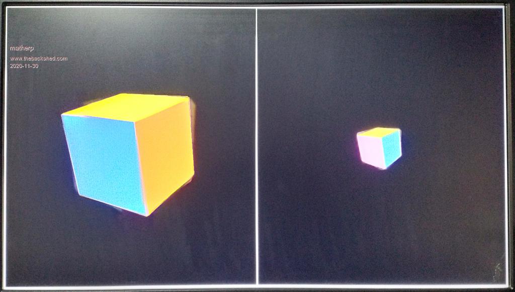 |
||||
| LeoNicolas Guru Joined: 07/10/2020 Location: CanadaPosts: 585 |
Pete, this is amazing. Thank you for all your work. I found some problems. 1) This is related to the Forum. The SSL certificate has expired. 2) When I move the create quaternion command to before the main loop the cube doesn't rotate. I did this test because I'm not modifying the rotation angle and I tried to use the same rotation quaternion for all iterations. This means that the draw3d rotate command is modifying the rotate quaternion array. 3) This second problem is weird. I changed the quaternion angle and instead of using a constant, I used rad(angle) directly inside the math q_create command. After doing this change the cube stopped to rotate. Now a question. You fixed the near and far camera parameters in 1 and 6 (fixed Frustum depth). Is it not better to allow us to specify these 2 values? Edited 2020-11-30 04:13 by LeoNicolas |
||||
| matherp Guru Joined: 11/12/2012 Location: United KingdomPosts: 11604 |
Don't understand - works for me. Same problem as above? Not sure what you mean - please explain further |
||||
mclout999 Guru Joined: 05/07/2020 Location: United StatesPosts: 510 |
Hi All. I have little experience with 3D and though the posts by matherp are helping I think I need some more rudimentary reading on the subject so I can get a better handle on this subject. Anyone have some good resources for basic 3D graphics? Thank you for any help with this. They call me Shai-Hulud (The maker) |
||||
| mkopack73 Senior Member Joined: 03/07/2020 Location: United StatesPosts: 261 |
Just a suggestion - you might want to change this to allow for scaling in each of the 3 axis (x/y/z). For example, I should be able to define a basic cube, and then use scaling to turn that single object into a number of different rectangles just by scaling each of the axis differently... Of maybe I want to take one model and stretch it vertically, but not horizontally, etc. If you were doing the transforms using matrices then this is actually a very simple set of operations in a couple of the cells of the transformation matrix (usually listed as SX,SY,SZ (for scale x, y, z accordingly). |
||||
| matherp Guru Joined: 11/12/2012 Location: United KingdomPosts: 11604 |
Nothing to do with 3D modelling. Obviously this can be done easily with a Basic function or using the existing MATH commands (SLICE, SCALE, then INSERT) e.g. in same program MATH SCALE vertices(), 100, vertices() dim float slice(7) math slice vertices(),0,,slice() math scale slice(),2,slice() math insert vertices(),0,,slice() Edited 2020-11-30 05:15 by matherp |
||||
| LeoNicolas Guru Joined: 07/10/2020 Location: CanadaPosts: 585 |
The near / far planes are the clipping planes for the Z axis. 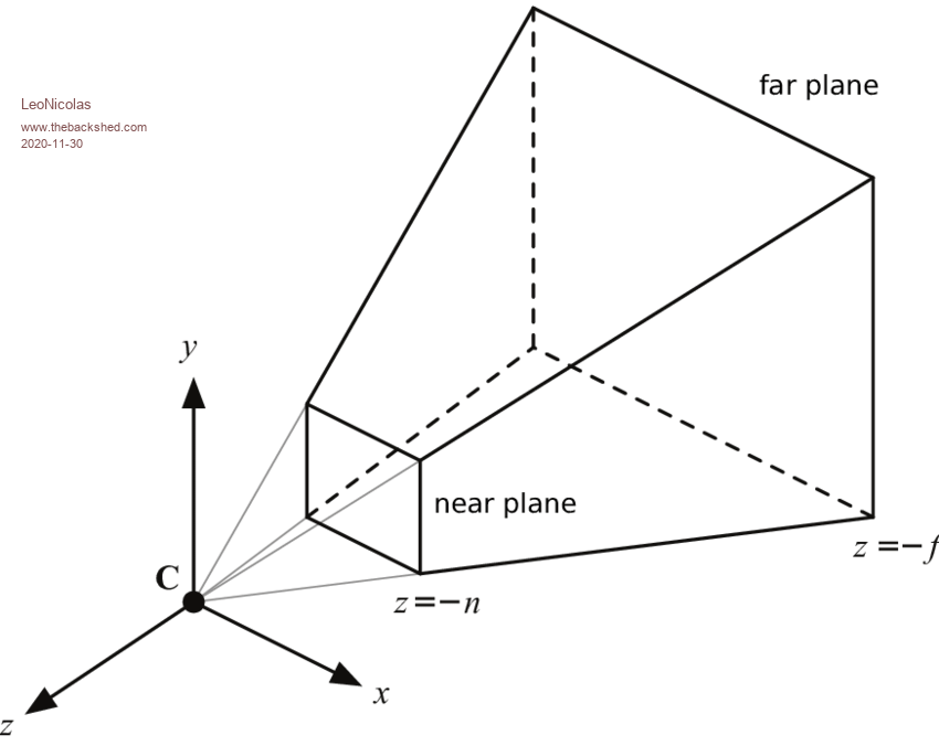 They are part of the perspective projection matrix: 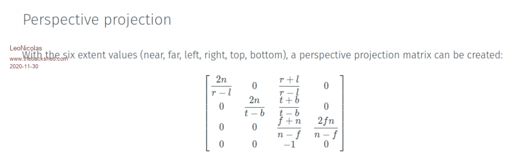  https://jsantell.com/3d-projection/ |
||||
| vegipete Guru Joined: 29/01/2013 Location: CanadaPosts: 1182 |
Amazing work! Absolutely smashing job!  But. Very sorry, but... Perhaps I am viewing things from the wrong perspective, but something seems backwards in some of these definitions. You say all cameras look along 'their' Z axis, then you specify an X and Y for each camera. Eh? If a camera is looking along 'the' Z axis, then by definition the camera's X and Y are zero. (Actually, I think I get this: the camera X,Y are screen coordinates, not 3-space coordinates. They specify where on screen to center the camera view.) In my opinion, the relative positioning of camera and object is unclear. Mathematically it doesn't matter, but clarity is always good. You say:But you can't. The object is defined as centered at 0,0,0. Instead, the camera has to be positioned 1000 away from the object. So where is the viewing plane? Yes, I know mathematically it doesn't matter, but it is conceptually simpler if you don't go moving objects around because the camera is stuck. Rather, unstick that camera. ;-) Could you explain why multiple cameras are required? I could understand 2 cameras for stereoscopic imaging, but why more? I detect also a disconnect between the ideas of objects and of a 'scene'. It seems that at the moment, the engine can display the view of one object, as seen by a camera. There is no concept of a scene, consisting of multiple objects at various positions and orientations. I don't know how it's normally done, but it seems to me there are two quite distinct parts to displaying 3D on screen: 1) a model of the 3D world, consisting of one or more objects, positioned in space, and 2) the view of that model, as seen by a camera. It takes 6 coordinates to position anything, an object or a camera, in 3-space: 3 for position, 3 for orientation. The engine is part way there. Objects are stuck relative to x,y,z = 0,0,0. The camera is stuck looking along the z-axis. None the less, this is an awesome start! Visit Vegipete's *Mite Library for cool programs. |
||||
| vegipete Guru Joined: 29/01/2013 Location: CanadaPosts: 1182 |
Excellent graphics. Are the near and far planes for image generation convenience? In other words, items beyond the far plane are too far away to see (clearly) so don't bother calculating them? And items closer than the near plane are too close so ignore them? How would you reconcile this with, say, reading a notice stuck on the face of a 3-D cube? Or a 3D edge that passes almost, but not quite, through the camera? Or put another way, how do you select where the near plane should be? Visit Vegipete's *Mite Library for cool programs. |
||||
| LeoNicolas Guru Joined: 07/10/2020 Location: CanadaPosts: 585 |
Peter I'm experiencing a lot of issues in the 3D examples. I recorded a video to show you what is happening. The camera example is not moving the camera and the cube example is stopping to rotate the cube when I try to change the rotation angle. https://youtu.be/lR_S-7ncXVk |
||||
| LeoNicolas Guru Joined: 07/10/2020 Location: CanadaPosts: 585 |
Vegipete Normally the far argument is used for improving the render performance in complex scenes reducing the horizon distance. We can see the far effect in games when the far objects appear in the scene suddenly. https://www.youtube.com/watch?v=Sfy6pB0susM&ab_channel=Udacity |
||||
| matherp Guru Joined: 11/12/2012 Location: United KingdomPosts: 11604 |
You are The world is 65532 x 65532 x 32766 units and the camera(s) is at any position x, y ,0 Objects are defined relative to their own centre but are placed in the world based on the x,y coordinates used in the SHOW or WRITE command. Object rotate around their own centre and it is up to the Basic programmer to calculate the correct x,y,z if they want to effectively rotate around some other point in the world |
||||
| Page 1 of 6 |
|||||
| The Back Shed's forum code is written, and hosted, in Australia. | © JAQ Software 2026 |
