
|
|
Forum Index : Microcontroller and PC projects : For those too young to remember the CMM2
| Author | Message | ||||
| matherp Guru Joined: 11/12/2012 Location: United KingdomPosts: 8601 |
Harm It isn't a crystal but a crystal oscillator package which is what fixed the issue for the original CMM2. The CMM2 G2 is a 4-layer board with a complete ground plane as the second layer - always has been - there is no way it could be routed with two layers. Noise could conceivably affect the 32KHz crystal but that is supplemented with the DS3231 RTC so the time is reset regularly. Unfortunately the way the STM32H7IIT6 pinouts works means that it is inevitable that you ware going to have wires all over the place Current state of the layout without the GND and VCC planes and about 6 wires left to route. As you can see, there is very little near the crystal oscillator or 32KHz crystal. Red - top, blue - botttom, green - VCC layer. No routing on the GND layer  Edited 2024-02-26 18:31 by matherp |
||||
| Volhout Guru Joined: 05/03/2018 Location: NetherlandsPosts: 3569 |
Hi Peter, The crystal oscillator will take care of the jitter. Perfect. For the 32kHz oscillator, maybe move the HSYNC and VSYNC away from the oscillator pins. In my company we have to be very strict in this sort of circuits, since we have been hit by problems before. I may be to conservative. It is a general rule, that if you have 3x clearence over 1x copper trace width, the coupling between signals is minimal versus used board area. So a 10 mil trace would require 30 mil isolation from nearby signal traces. You could apply that (as good as you can) for the 32kHz oscillator. But also (where possible) between HSYNC and VSYNC. It may not be possible everywhere, but especially in larger runs it helps when there is distance between them for the majority of the run. Signals that are especially affected are "higher impedance" signals, such as crystal oscillators, but also I2C...  Regards, Volhout Question: what is the H5 header for ? Edited 2024-02-26 19:17 by Volhout PicomiteVGA PETSCII ROBOTS |
||||
| matherp Guru Joined: 11/12/2012 Location: United KingdomPosts: 8601 |
Harm: thanks for the feedback H5 is the BOOT/RUN select header. Previously to flash a new version you had to open the box to move the header. In this layout you can move the header through the front panel. |
||||
| Mixtel90 Guru Joined: 05/10/2019 Location: United KingdomPosts: 5758 |
I wondered what H5 was, but was afraid to ask. ;) Mick Zilog Inside! nascom.info for Nascom & Gemini Preliminary MMBasic docs & my PCB designs |
||||
| matherp Guru Joined: 11/12/2012 Location: United KingdomPosts: 8601 |
Here is the "final" layout. I've omitted the GND plane but this sits between the top layer (red) and the VCC plane (green) with the bottom layer (blue) at the bottom (obviously). The ground plane has no tracks  Edited 2024-02-26 21:38 by matherp |
||||
| Volhout Guru Joined: 05/03/2018 Location: NetherlandsPosts: 3569 |
Hi Peter, Have no idea about U15 (3.3V regulator) dissipation, would it need some copper on the red layer added to the tab ? Volhout Edited 2024-02-26 21:40 by Volhout PicomiteVGA PETSCII ROBOTS |
||||
| matherp Guru Joined: 11/12/2012 Location: United KingdomPosts: 8601 |
Yes: I do this on the original. I just left it off for clarity |
||||
PilotPirx Regular Member Joined: 03/11/2020 Location: GermanyPosts: 66 |
When it's ready and tested: would anyone like to order this new assembled board in Germany? I would participate with a piece. |
||||
| geeken Newbie Joined: 13/01/2018 Location: United StatesPosts: 20 |
Peter, which size did the memory end up being for the new CMM2 design? G1 was 8MB, G2 was 32MB, so doubling or quadrupling this G2 amount would be mega-useful for large file processing - - - such as gaming / graphics processing. Thanks in advance for figuring the new design and getting it out the door. |
||||
| Mixtel90 Guru Joined: 05/10/2019 Location: United KingdomPosts: 5758 |
He's got G2 V2.0 written on the board so I assume it'll be 32MB. :) Mick Zilog Inside! nascom.info for Nascom & Gemini Preliminary MMBasic docs & my PCB designs |
||||
| atmega8 Guru Joined: 19/11/2013 Location: GermanyPosts: 712 |
Yes i would. But there should exist a case which can be printed with a 3 D Printer |
||||
| twofingers Guru Joined: 02/06/2014 Location: GermanyPosts: 1139 |
I would also be interested in a piece. A 3D printable case shouldn't be a problem. Regards Michael |
||||
| PilotPirx Regular Member Joined: 03/11/2020 Location: GermanyPosts: 66 |
No problem, i can build a case |
||||
| twofingers Guru Joined: 02/06/2014 Location: GermanyPosts: 1139 |
Oopps. Please cancel that! (wrong thread) |
||||
| Mixtel90 Guru Joined: 05/10/2019 Location: United KingdomPosts: 5758 |
There is a case available anyway. You can print one if you like, or you can order one of the following: Multicomp Pro G738 or G748A Instrument Case 140x110x35 mm Jaycar HB5970 Altronics H0472 Element14 1526699 Farnell 1526699 Rapid Electronics 52-4336 You also need 4x 5mm spacers and some fixing screws for the PCB. Edited 2024-03-04 23:49 by Mixtel90 Mick Zilog Inside! nascom.info for Nascom & Gemini Preliminary MMBasic docs & my PCB designs |
||||
| atmega8 Guru Joined: 19/11/2013 Location: GermanyPosts: 712 |
Thanks, but that's still an empty case. The cutouts for VGA, headphone, etc. still need to be drilled and filed? |
||||
| matherp Guru Joined: 11/12/2012 Location: United KingdomPosts: 8601 |
Once I've got the boards I'll do new dxf files for the end-plates. The existing G2 already has these. Just take the dxf, import to any decent cad program and create a stl of it. Then you can print the end-plates and use the standard box. Easier than trying to print the whole thing. Personally, I import the dxf into my laser cutter and then cut the ends out of plasticard. |
||||
| Volhout Guru Joined: 05/03/2018 Location: NetherlandsPosts: 3569 |
I have also seen people that order front and rear panel as PCB with silkscreen printing. For few dollar you have a 5 sets of faceplates... Volhout PicomiteVGA PETSCII ROBOTS |
||||
| atmega8 Guru Joined: 19/11/2013 Location: GermanyPosts: 712 |
OK, those End-Plates fit into the standard Multicomp Pro G738 or G748A Instrument Case 140x110x35 mm?? |
||||
| matherp Guru Joined: 11/12/2012 Location: United KingdomPosts: 8601 |
The boards have arrived and program and boot up perfectly. Once I've finished testing everything I'll post the gerbers 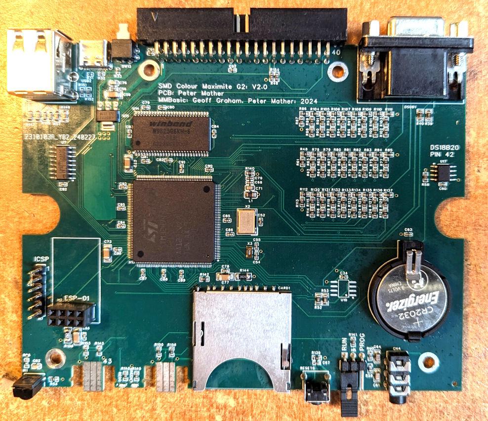 |
||||
