Notice. New forum software under development. It's going to miss a few functions and look a bit ugly for a while, but I'm working on it full time now as the old forum was too unstable. Couple days, all good. If you notice any issues, please contact me.
wiseguy Guru Joined: 21/06/2018 Location: AustraliaPosts: 1016
Posted: 05:42am 20 Apr 2024
Copy link to clipboard
Print this post
The Inverter code is nearing completion, the most recent version I received last night, I cannot fault its operation, but still testing.
The setup/calibration is realtively simple, the default values essentially would allow the inverter to run for a 48V system, when the code is loaded. However, for accuracy there are calibrations for Vcap & Vin, both calibrated in one step, then there is the calibration for AC output Voltage and current. Please be aware that the AC readouts whilst quite accurate for resistive loads should not be totally relied on for exact accuracy as they are essentially peak readings but calibrated as for RMS.
I recommend using a true RMS meter when calibrating the AC volts and amps. For stress free settings of AC Amps and over current trip at for instance 5kW loads, a 10T winding through the current sense transformer allows 1 A to look like 10A.
My method is to place a short length of 2.5mm enamelled wire through the current sense transformer, as the main current conductor from the inverter to the load. Now from the load side connect a 1mm enamelled wire and wind through the current sense transformer 9 more times and terminate the 3 wires onto a terminal block or similar.
Now a 500W load using the extra 9T will calibrate as for a 5kW load whilst only supplying a load of 2A instead of 20A. Another method is to use a 240V to 6 or 12V transformer wired with a 0.5 - 1 ohm resistor in series to a 1mm enamelled 10T winding and using a Variac (yes its coming....) and AC amp-clamp meter, you can calibrate the inverter AC Amp meter and the over current trip point as required.
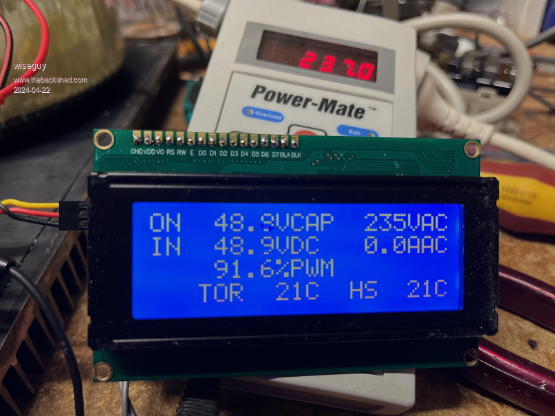
The display shows the applied input voltage (Vin), the actual Voltage of the main capacitor bank (Vcap) The 240V Mains output Voltage and Current, the % of PWM power drive 0.0 - 99.9% and heatsink and toroid temperatures and status of the 2 Fans. There is a "mains up", 12V open drain FET output to switch a relay that automatically connects the mains to the load when the ramp up is complete.
The test mode of the control PCB will allow the inveters PWM/Opto drive to run despite low capacitor bank and input voltages. This function is invaluable for initial testing or repair. Simply put the J11 link to test and apply 16V to the controller, the LCD reports "Test mode" the main capacitor bank can now be powered from a variable DC supply. A sinewave is generated on the toroids output from as low as 1VDC (about 7VAC from the mains). The drive waveforms & current consumption etc can be monitored as you advance the FET Power section voltage up to its normal voltage.
I had to temporarily stop work on the new Variac PCB testing, to concentrate on the software creation and testing of the main inverter which I (and probably Poida) underestimated the total amount of work required to beat it into shape.
Hopefully in the near future (a week if all goes well) I can tell you they are both finished and ready for manufacture, after we work out who wants what and how many.
I will post a picture soon of the actual display with the inverter working. Edited 2024-04-20 17:49 by wiseguyIf at first you dont succeed, I suggest you avoid sky diving.... Cheers Mike
wiseguy Guru Joined: 21/06/2018 Location: AustraliaPosts: 1016
Posted: 03:35am 22 Apr 2024
Copy link to clipboard
Print this post
Here are some pictures, first is the inverter operating display. Note the % of PWM on the 3d line is overwritten by fault/error messages if they occur. It is informative to note, if you multiply the Vin by the % ie 48.9 x 0.916 the answer is 44.79, that is the actual DC input voltage where my inverter drops out of AC regulation with no load. If you put 44.8V in it will be at 99%
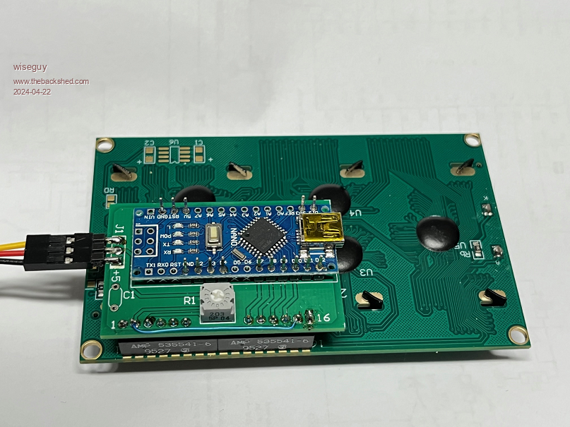
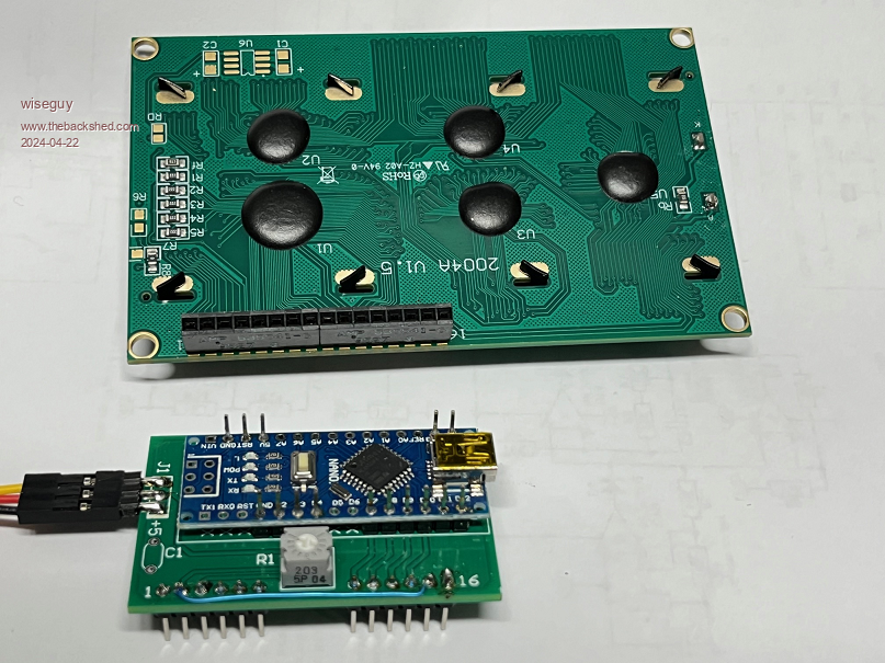
Then some pictures of the small Nano interface PCB I made cause I like neat tidy stuff. The LCD board will be in its 3d revision when it is next ordered. I will be supplying them for 50c ea with orders. Bad news is you need to run a jumper wire from +5 to pin 15 and join pin16 to ground if you want the backlight to work, this is for the first 20 odd display boards shipped out, after that it will be the new Rev.
The astute readers will notice that the black wire is shown deftly plugged into the +5 pin, I just plugged it in for the picture, it wont work very well if you actually do this.....
The third revision (I start at Rev0 so board shows Rev2) is as pictured below, you will see there are two pads that can be solder bridged to enable the backlight. In a typical room the black on green displays are quite readable with no backlight, but the blue displays really need one. Some LCD modules do not use a current limiting resistor, and their LEDs are directly on pins 15 & 16. So if you have one of those LCDs a suitable value SMD part (or through hole part - a bit fiddly!) can be soldered to the pads. Suggest starting with 470R and adjusting up or down as required. Both the recent ones (Blue and Green) I bought from different Ali suppliers had the current limit resistors fitted as standard.
Although I show a plug in connector fitted to the display module it makes the interface board feel a little "wobbly" when plugged in, I think the interface PCB should be soldered direct to the display but spaced from the back of the LCD by at least 5 or 6mm. The 3 pins for J1 can be soldered vertically - or as I have done, horizontally.
The board can be constructed using just the 2 x 15 rows of pins the Nano PCB's are supplied with and the little dual row header is not required to be soldered to the Nano if you buy them unassembled. Not all pins of the Nano or LCD are required to be connected so by cutting 3 lots of 6 pins 2 of 3 pins and 1 each of 4 & 2 pins. Some of the Nano pins are not required but the spare connectors were used for good stable anchoring. Edited 2024-04-22 13:58 by wiseguyIf at first you dont succeed, I suggest you avoid sky diving.... Cheers Mike
poida Guru Joined: 02/02/2017 Location: AustraliaPosts: 1392
Posted: 08:41am 22 Apr 2024
Copy link to clipboard
Print this post
this is looking nice, WG
The PWM % is very useful in sorting out how many turns you really need for the primary.
Most times I build or comment on this, I suggest a primary that will run at the required AC output at 80% PWM This allows for some voltage drop from the battery, through the power bridge. And it allows for some drop through the primary & choke(s). My build always use far too small primary conductor copper area 'cos I am cheap/stupid but the inverter is built for low power for most of the time and 10x low power for 5 or 10 minutes max. bursts. Let things get warm and let the fans cool things down, plz.
If you build an inverter with good, thick primary cable and good thick battery cable and 4 FETs x 4 or even 6 x 4 then you could get away with running at higher PWM % This would be good, it means lower DC current (from battery and through FETs) and lower PWM current in the primary and choke(s). (lower DC current means better efficiency)
This PWM % will be a useful design tool for optimising the build.wronger than a phone book full of wrong phone numbers
wiseguy Guru Joined: 21/06/2018 Location: AustraliaPosts: 1016
Posted: 09:28am 09 May 2024
Copy link to clipboard
Print this post
This has been quite a saga to get the Variac to the point where I was happy with it, It also reminded me of the perils of simple design.
The main problems were in the metering circuits, initially in the inverter The AC volts would normaly live in the 200 - 250VAC region so nominal accuracy only required over this range it was really meant as a voltage monitor not a precision volt meter so I chose to use a peak reading circuit that was calibrated to the RMS value.
Likewise the current meter used a peak reading scheme calibrated as for RMS, again it was a bit of a novelty to have some indication of volts and current - I was well aware that complex loads and half wave and chopped AC would add an error to the readings but for resistive loads it would be very good.
We did graph results of the circuits I used for V & I and the results were impressive but as we were to later find out also reliant on your luck as to what the offsets were in the IC you happened to pick up. Despite the opamp I chose having very low offsets they could still be problematic. So the new prototype gave different results to the bread boarded circuit so back to the drawing board for a while.
Given that a typical Variac has usually a 0-100% rotary scale or a 0-260VAC scale that in my experience it is usually somewhere between +/- 10 to 20VAC accurate and never stable, The included metering should be really useful. But the problem was the poor performance at the low end, This would lead to 2 or 3 V showing with the inverter off, the same with Amps.
In the end there was no simple cure and I had to create a negative rail, which turned out to be ~ -3.5V using a LMC555 (CMOS NE555) and a few bits for a charge pump from the 5V supply. Then with 2 x trimpots between the +5 and -3.5 I could inject a small offset trim to the inverting opamps inputs and set them so that from a positive meter reading you trim down until the 0 just appears, voila done!
As it turns out the Metering now is really good. Accuracy against my bench DVM is within 1V from 4V - 250V (the Variac only has whole volt LCD metering) the current is also really good. At 120mA it is within 10mA and at 3.9A it is within 20mA over the whole range.
So today I sent out another revision which I believe will be the final one and as I had another PCB I needed with a fast turn around it should be here by late next week.
I also need to thank Poida for regular updates to the code as various schemes were tried for all sorts of gremlins but now it is a really good useful device. The active current limiting is a brilliant feature that Poida added and is something a Variac could never match.
I have an ornery 100W RMS x 2 amplifier that can eat up darlington output devices in mere moments. Of course the Amplifier is semi smart and needs a minimum AC input before speaker protectors function etc. Although quiescent looks about right there is not a runaway issue more like a gallop away issue that sees almost instant destructions of the output devices with no warning. I suspect that I will be able to set the constant current to just above the mains idle current and finally stop the destruction and let me see what is happening to the circuitry. Its just theory but I reckon it has a chance of helping. I think I am ready now to start the list of who wants what - please wait though for a few more posts of what will be available and how they can be configured. Whilst I am getting the lists together the revised variac board should be here late next week, I will build one up hastily to make sure there are no issues before pulling the pin and placing a quantity order.
Meanwhile KeepIS has proved the inverter controller seems to work well in his build, 400A peak input @ 48V, lets see who can beat that lol. Edited 2024-05-09 20:21 by wiseguyIf at first you dont succeed, I suggest you avoid sky diving.... Cheers Mike
wiseguy Guru Joined: 21/06/2018 Location: AustraliaPosts: 1016
Posted: 03:59pm 10 May 2024
Copy link to clipboard
Print this post
I have finally compiled a list of the bits required to make either a Variac/Inverter or a pretty "grunty" Inverter
Both Units can be run from 24V to 60V, with a suitable primary winding on the Toroid.
2.5KW Variac/Auxiliary inverter
WG40 Rev1: x 1 8 x Mosfet Power PCB..................100 x 100......$2 WG41 Rev1: x 1 Opto + Gate-drive + Cap PCB......100 x 100......$2 WG44 Rev2: x 1 Nano Serial to 40 x 2 LCD...........49.5 x 33........$0.5 WG45 Rev1: x 1 Variac Nano Controller PCB..........100 x 100.....$2
6kW Inverter (Note easily handles peaks over 15kW)
WG06 Rev1: x 2 4 x Bulk Cap PCB for WG30........100 x 100......$2 WG30 Rev1: x 1 16 x Mosfet Power PCB 2oz........260 x 108......$10 WG39 Rev6: x 1 Inverter Nano Controller...............100 x 100......$2 WG44 Rev2: x 1 Nano Serial to 40 x 2 LCD...........49.5 x 33.......$0.5
The pricing is budgetary and no freight is included, when all the quantities are ordered and final freight is known it will be divided down proportionally + local delivery. I expect Local delivery to be ~ $7 max. As said before I will include a free 160A current sense transformer (new) for each Inverter or Variac controller ordered. So budget for a max of $6.50 for the Variac and $14.50 for the inverter.
The Controllers can both drive the smaller power board or the larger board, plugs have same pinout.
The manufacture of the new Variac boards revision update are at 93% completion so will be winging their way back very soon. Edited 2024-05-11 02:08 by wiseguyIf at first you dont succeed, I suggest you avoid sky diving.... Cheers Mike
nickskethisniks Guru Joined: 17/10/2017 Location: BelgiumPosts: 428
Posted: 09:00pm 10 May 2024
Copy link to clipboard
Print this post
I don't know if there is interest but a feature the nanoverter hasn't got yet (apart from the uart/usb), is a communication bus.
A can bus could be a simple feature added on the Nano Serial to 40x4 pcb, it would make it a little bit bigger though, but measurements could be made accessible.
wiseguy Guru Joined: 21/06/2018 Location: AustraliaPosts: 1016
Posted: 07:49am 11 May 2024
Copy link to clipboard
Print this post
Hi Nicks, to be honest this project has taken a big slab of time and I am pretty well done with it - the end is finally in sight, and I am sprinting fast to the finish line.
I am worried it could turn out to be a CAN of worms, CAN & software generally is not my forte, I prefer hundreds of amps to digital stuff. There is also nothing to stop that as an enhanced separate add on later, but I propose to not get diverted at this time.
If you are prepared to discuss with Poida if required re baud rate etc and come up with a schematic or module and confirm how it will connect, I will consider it for later.If at first you dont succeed, I suggest you avoid sky diving.... Cheers Mike
KeepIS Guru Joined: 13/10/2014 Location: AustraliaPosts: 1399
Posted: 04:17am 12 May 2024
Copy link to clipboard
Print this post
I'm about to build another controller board for the backup inverter, so apart from A7 link and some minor overlay markings, are there any real differences between the test board that I'm using and the final controller board?
If there is, I'll hold off until the release of the final board, tnks.It's all too hard. Mike.
nickskethisniks Guru Joined: 17/10/2017 Location: BelgiumPosts: 428
Posted: 08:14am 12 May 2024
Copy link to clipboard
Print this post
I can imagine, I'm also a fan of not to many bells and whistles but some things are nice to have. I will work on it on the background and try to make it backwards compatible.
poida Guru Joined: 02/02/2017 Location: AustraliaPosts: 1392
Posted: 09:40am 12 May 2024
Copy link to clipboard
Print this post
canbus support might be possible but it depends on interrupt priority. the PWM interrupt must not be preempted.
a common canbus interface uses SPI. I would avoid Arduino SPI library and do it in steps as allowed by the time spare in the PWM interrupt routine.
the canbus code (that does the data conversations) will need to be in something that is NOT the PWM interrupt code block.
It sounds like a lot of work (and "work" is a 4 letter word in my world)
the PWM interrupt needs to run at 20 kHz and complete in less than 1/20,0000 seconds, in fact a lot less than that time (50 ms)
my bit bang serial data output needs only 5 uS, on top of the 10-15 us for the inverter PWM code to complete. there is NO spare time to use for canbus conversations in the interrupt code block.
You can use the spare time (what is left after the PWM interrupt code ran) to do the canbus conversation but if you choose to use the SPI library or even worse, the canbus library for various chips, then there will be long and unexpected pauses inside the PWM code block. think much longer PWM pulses. this means over current situations for inductors and FEts
I will not help you with this idea. I do not like it at all.wronger than a phone book full of wrong phone numbers
wiseguy Guru Joined: 21/06/2018 Location: AustraliaPosts: 1016
Posted: 10:04am 12 May 2024
Copy link to clipboard
Print this post
Peter, I think Nicks was looking at it from the LCD nano controller and whether a CAN bus could be simply added on to the LCD Nano. I am guessing he just wants to relay on the LCD information on the CAN bus. I read his his query as can I have back (free up) the real serial port pins of the LCD Nano for the CAN interface and swap some other free pins for the ones just stolen for the LCD drive.
This is not to suggest I love it or you will too, just saying what I think Nick is after, yes I think the Inverter controller Nano has enough/plenty to do already.
I am reviewing the controller with a view to adding a couple of pots to remove any positive offset. For the dual MCP6002, nine out of ten chips work ok with no positive offset - so its either add more bits or juggle the existing chips around to find a combination that has no positive offset for the LCD readout.
I could also make it so that a single select resistor is inserted to just remove/cancel any positive offset, which takes up less room and is the way I am leaning for now.If at first you dont succeed, I suggest you avoid sky diving.... Cheers Mike
Revlac Guru Joined: 31/12/2016 Location: AustraliaPosts: 964
Posted: 10:44am 12 May 2024
Copy link to clipboard
Print this post
this is 2 pcb's at $2 each is it?
Sounds great, really impressed with the work put in to this. My big inverter, the 8010 chip on a carrier give up the ghost yesterday, put in a spare chip ad its running today doing some welding....story for later in its own thread. Obviously Its a good idea to have a backup, so very interested in this new inverter design. Cheers Aaron Off The Grid
nickskethisniks Guru Joined: 17/10/2017 Location: BelgiumPosts: 428
Posted: 11:01am 12 May 2024
Copy link to clipboard
Print this post
Yes, exactly Mike, I will not touch a good working code (at the moment :p). Just looking for a simple way to combine and read all measurements from distance.
I recently made (still a bit of finishing to do) a proto electronic load for testing powersupplies at work (buck converter with resistor as load) and I needed to do the I²C bus and the spi bus on the right moments, updating the lcd (for debugging) was frustrating in the beginning when doing everything with 1 nano. So it learned me a bit what's involved there. There are 2 loads inside, for testing +-24V 16A, both loads are controllable with 2 potmeters or over can with isolated can transceivers. There is display with can interface that pols the can devices and displays some measurements. At that moment I wanted to learn a bit about can so I used that.
So from there my motivation, now interest grows to connect all my diy electronics with 1 can bus at home. Instead of using usb ports/hubs on the RPI, I blew 1 pi usb bus already experimenting with my eltek psu while doing this(connected to the generator). A can bus could serve as extra safety buffer between devices and PI.
I will go further in another thread for asking advice when needed. I first need to document my little nano boost MPPT controller. I will include a can interface, this work I can share over here without getting in to trouble.
Count me in for some WG boards, knowing you guys put lots of effort/time/love in this new revision I can't do better. Last time it was quite pricey to import something from AU, so don't know if there is a budget friendly way for EU. But I'm happy to pay for premium stuff if there is none. Edited 2024-05-12 21:14 by nickskethisniks
wiseguy Guru Joined: 21/06/2018 Location: AustraliaPosts: 1016
Posted: 03:25pm 12 May 2024
Copy link to clipboard
Print this post
Yes Aaron that's correct 2 x PCBs 100 x 100 with 4 x Bulk Caps up to 35mm dia. on each board. 8 Caps in total - if you want that many...... Edited 2024-05-13 01:26 by wiseguyIf at first you dont succeed, I suggest you avoid sky diving.... Cheers Mike
rogerdw Guru Joined: 22/10/2019 Location: AustraliaPosts: 814
Posted: 02:23pm 13 May 2024
Copy link to clipboard
Print this post
Hi Mike, I'd like to order two complete sets of boards for the inverter please ... plus an extra WG39 Rev6: x 1 Inverter Nano Controller
I'd like to have a spare inverter around and a friend is starting to sound interested in building one up. Might as well be prepared. Thank you.Cheers, Roger
mab1 Senior Member Joined: 10/02/2015 Location: United KingdomPosts: 173
Posted: 10:49pm 13 May 2024
Copy link to clipboard
Print this post
Hi Mike,
If you can post to the UK, could I order a complete set of inverter boards and a complete set of Variac boards please?
Plus, (if it's a remotely workable idea to graft one onto a Chinese power board in place of the EGS002) i too would like an additional WG39 inverter nano controller please.
Thanks very much for all your (& Poidas) hard work on this.
P.S. if there happen to be any of Poidas MPPT boards going spare around your neck of the woods, I'd not say no to a couple of sets...
wiseguy Guru Joined: 21/06/2018 Location: AustraliaPosts: 1016
Posted: 06:07am 14 May 2024
Copy link to clipboard
Print this post
Roger & Mab yes your requests are noted, thankyou - to everyone else please just wait a few more days whilst I build up the new revision Variac board.
Mab with regard to grafting a controller onto a Chinese power board I will look into it. Can you check my member details for email address and email me a few pictures (a schematic would also be good - if you have one) of the Chinese board in question.
I expect by the end of this week I will post a list of who has ordered what so far and call for others to place posts here of the boards they are after ie for Variac or Inverter sets.If at first you dont succeed, I suggest you avoid sky diving.... Cheers Mike
mab1 Senior Member Joined: 10/02/2015 Location: United KingdomPosts: 173
Posted: 08:22am 14 May 2024
Copy link to clipboard
Print this post
Hi Mike, Regarding the chinese board: apologies, I didn't mean to add to your workload - for the small price of another board i may as well just get one, and when i eventually look at it i can post here for feasability and advice (unless you really want to do it of course ).
Murphy's friend Guru Joined: 04/10/2019 Location: AustraliaPosts: 600
Posted: 09:27am 14 May 2024
Copy link to clipboard
Print this post
Mike, can you please clarify something for me?
It's the name "variac" that confuses my brain, what exactly different does it do from the original nano control board that Poida created for the inverter to replace the EG8010 chip?
That is, if I'm not confusing this board's function with some other project .
wiseguy Guru Joined: 21/06/2018 Location: AustraliaPosts: 1016
Posted: 12:27pm 14 May 2024
Copy link to clipboard
Print this post
Copied from KeepIS's thread where I accidentally posted this reply.
Klaus I apologise in advance for the verbose reply.....war and peace here we go
With regard to your question about what the Variac is, I will assume you have seen and used a Variac before and I would be most surprised if you had not. For newbies who are maybe not familiar, a Variac is special type of adjustable transformer or a VARIable AC device or VARIAC.
The normal units are essentially a special type of toroidal tranformer that has a single layer winding and for descriptive puproses has the varnish missing from the bottom side. There is a shaft through the centre with an arm and a wiper contact that can touch individual wires as the shaft is rotated. Lets assume it has 100T and we apply 100V across the winding ends. If we meter from one end of the winding as we touch the wiper to the first winding - 1 Turn - we will measure 1V, and if we rotate the wiper to touch the 20th turn we will measure 20V etc.
Sometimes it is handy to have a variable AC source that we can slowly increase the voltage to something we wish to test in a safe manner and we can monitor input current against the increasing voltage and stop if things are not looking good.
In the Nano inverter there is a fixed reference voltage within the Nano and it compares the output AC level to the fixed reference and drives the PWM higher until the sample of the output voltage matches the reference level, thereby regulating a constant fixed AC output.
Poida created some code that had no feedback from the output, instead it has the usual feedback pin tied to a variable resistor (5V on the pots top end, ground on the other) and the code creates a PWM that is proportional to the wiper setting. So in theory a 2.5V midpoint pot setting will create PWM of 50% duty cycle modulation.
The only issue with that is the dynamic performance of the Toroid and output stage will cause the output voltage to sag when a heavier load is applied. So I created some analog control that compares the output level to the pot setting and if the output starts to sag it increases the control voltage to the Nano slightly to compensate for it.
Next unless you have paid a lot for a Variac it has no volt or current metering and a rough and ready 0-100% or 0-260V scale that is very inaccurate and dependent on the actual mains voltage at any given moment. The Nano variac has volts & current metering and a settable current limit, which causes the output volts to drop to whatever level is required to maintain the current limit setting.
If you ever want to calibrate something to a fixed AC level, be it current or voltage the Nano Variac is a very stable AC source and stays exactly where it is set so you are not trying to chase the varying mains voltage or current as it wobbles around ad infinitum.
Lastly it operates from a DC source from 16 - 60V but the transformer primary has to be wound to suit the applied voltage. No doubt 99% of users will either use their 24V or 48V storage supply and suitable Toroid. Of course if there is no mains power and the primary inverter has also died the Variac can be set for 240V and with the small 8 FET Power board should easily supply 2.5kW to bring your fridge to life and turn on a lamp and power your soldering Iron for the primary inverter repair. Edited 2024-05-14 22:22 by wiseguyIf at first you dont succeed, I suggest you avoid sky diving.... Cheers Mike


 .
.